HAL Id: hal-00819075
https://hal.inria.fr/hal-00819075
Submitted on 30 Apr 2013
HAL is a multi-disciplinary open access
archive for the deposit and dissemination of
sci-entific research documents, whether they are
pub-lished or not. The documents may come from
teaching and research institutions in France or
abroad, or from public or private research centers.
L’archive ouverte pluridisciplinaire HAL, est
destinée au dépôt et à la diffusion de documents
scientifiques de niveau recherche, publiés ou non,
émanant des établissements d’enseignement et de
recherche français ou étrangers, des laboratoires
publics ou privés.
Analyzing Flowgraphs with ATL
Valerio Cosentino, Massimo Tisi, Fabian Büttner
To cite this version:
Valerio Cosentino, Massimo Tisi, Fabian Büttner. Analyzing Flowgraphs with ATL. Transformation
Tool Contest, Jun 2013, Budapest, Hungary. �hal-00819075�
Analyzing Flowgraphs with ATL
Valerio Cosentino, Massimo Tisi, and Fabian B¨uttner
AtlanMod, INRIA & ´Ecole des Mines de Nantes, France {massimo.tisi, valerio.cosentino, fabian.buettner}@inria.fr
Abstract. This paper presents a solution to the Flowgraphs case study for the Transformation Tool Contest 2013 (TTC 2013). Starting from Java source code, we execute a chain of model transformations to derive a simplified model of the program, its control flow graph and its data flow graph. Finally we develop a model transformation that validates the program flow by comparing it with a set of flow specifications written in a domain specific language. The proposed solution has been implemented using ATL.
Keywords: Model-Driven Engineering; Model Transformation; ATL; Flowgraphs.
1
Introduction
This paper presents an ATL-based solution to the Flowgraph Case Study [8] for the Transformation Tool Contest 2013 (TTC 2013) [7]. The main task of the case study is deriving the program dependence graph (PDG) of the given source code. This graph contains both control and data flow information and is obtained through a sequence of steps: 1) creation of a simplified model for the java program; 2) generation of the program control flow graph; 3) addition of data flow dependencies to create the PDG. A final additional task is 4) validate the resulting PDG against a set of specifications written in the provided DSL.
The solution is implemented using an ATL transformation chain. We address all the tasks of the case study by relying exclusively on the ATL declarative language, with the exception of text-to-model injectors and global orchestra-tion. The case study shows the flexibility of ATL in handling a wide range of tasks: classical model-to-model transformation and model-to-text transforma-tion in task 1, in-place refinement in task 2, complex algorithm in task 3, model validation in task 4. It is also intended as a full-range example for new ATL developers.
This paper is structured as follows: Section 2 introduces ATL; Section 3 details the sequence of tasks in the case study; in Section 4, we illustrate our solution; finally Section 5 discusses the solution w.r.t. the case study evaluation criteria and concludes the paper.
2
ATL Transformation Language
The ATL Transformation Language (ATL) [5] is a model transformation lan-guage and tool available from the Eclipse modeling project [3]. ATL is a declara-tive language allowing the specification of transformation rules, that are matched over the source model to create elements in the target model. Expressions are written using the Object Constraint Language (OCL) [6]. ATL contains also an imperative part allowing to handle cases whose declarative expressions would be too complex. The solution we propose in this paper makes use only of the imperative part of the language.
ATL allows the developer to decorate the input metamodel with derived at-tributes and operations on model elements, named Helpers and grouped into reusable Libraries. Finally the developed transformation can be applied in nor-mal mode, where target models are built from scratch, or in refining mode, where the input model is modified in-place.
3
The Flowgraphs Case Study
The Flowgraphs case study for TTC 2013 is a sequence of 4 tasks:
– In task 1, given a Java source file, the transformation tool has to generate a simplified model of the file conforming to the provided FlowGraph meta-model. Parsing of source code and creation of an initial model is performed by the EMFText JaMoPP-Parser, provided by the case study as a JAR file, that generates EMF models conforming to the JaMoPP metamodel. The trans-formation has to derive a model conforming to the FlowGraph metamodel. All elements in a FlowGraph model have a txt attribute: the transformation has to set the value of this attribute to the concrete Java syntax of the state-ment or expression. This can be considered as an embedded model-to-text transformation.
– In task 2 the FlowGraph model of the program is refined, by adding edges for control flow dependencies cfPrev and cfNext.
– In task 3 a further model refinement adds data flow edges, dfPrev and dfNext to the FlowGraph model. This task requires to extend the transformation from task 1 so that it also creates Var objects for local variables and Param objects for method parameters, and connect each instruction to the variables it reads and writes.
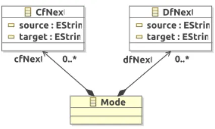
– In task 4 the user provides flow specifications written in a textual DSL and the transformation tool checks these specifications against the model generated in task 3. In this paper we will use the DSL proposed by the case study, of which we give an example in Listing 1.1. We implemented a text-to-model injector using XText [4]. The simple metatext-to-model and XText grammar we developed are shown in Fig. 1 and Listing 1.2. The injector is included as an executable JAR file in the solution package, together with the necessary libraries.
3
Fig. 1. Metamodel for the Validation DSL.
Listing 1.1. Example of textual specifications.
c f N e x t : " t e s t M e t h o d ( ) " - - > " i n t a = 1 ; " c f N e x t : " i n t a = 1 ; " - - > " i n t b = 2 ; " c f N e x t : " r e t u r n b * c ; " - - > " E x i t " d f N e x t : " i n t a = 1 ; " - - > " i n t c = a + b ; " d f N e x t : " i n t b = 2 ; " - - > " i n t c = a + b ; " d f N e x t : " i n t c = a + b ; " - - > " a = c ; "
Listing 1.2. XText grammar for the validation DSL.
M o d e l : c f N e x t+=C f N e x t+ d f N e x t+=D f N e x t +; C f N e x t : ’ c f N e x t : ’ s o u r c e=T e x t ’ - - > ’ t a r g e t=T e x t ; D f N e x t : ’ d f N e x t : ’ s o u r c e=T e x t ’ - - > ’ t a r g e t=T e x t ; T e x t : S T R I N G ;
4
An ATL solution
Structure of the solution. The solution is an Eclipse project available on [2]. The project requires an installation of Eclipse with EMF and ATL. It has been tested on an Eclipse Modeling Tools bundle v4.2, with the addition of ATL v3.3.1 from the Eclipse Modeling Components Discovery tool.
The top-level folder ttc-2013-flowgraphs-case-ATL contains the following di-rectories:
metamodels: the JaMoPP metamodel (java.ecore and layout.ecore), the Flow-Graph metamodel and the Validation metamodel.
source-files: the Java files to transform.
source-models: the JaMoPP models generated by the JaMoPP-Parser from the files in source-files.
results: the resulting models of tasks 1-3 with respective suffixes -StructureGraph.xmi, -ControlFlowGraph.xmi, -ControlFlowGraph-with-Vars.xmi, -DataFlowGraph.xmi. validation: all the files for task 4. The user writes a specification file with the
same name of the corresponding Java source file and extension .val. The specification file is injected in an XMI model and the result of the validation is stored in a text file with extension .result.
lib: the required JARs, including JaMoPP-Parser, ANT-contrib, and the Vali-dation DSL injector.
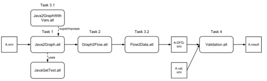
The ATL transformations are located in the top-level folder and are orches-trated by an ANT file that launches all the transformations for each one of the Java files. The structure of the chain is illustrated in Fig. 2 and detailed in the following.
Java2Graph.atl
JavaGetText.atl
Graph2Flow.atl Flow2Data.atl Validation.atl
A.xmi uses A.result A-DFG. xmi A.val. xmi
Task 1 Task 2 Task 3.2 Task 4
Java2GraphWith Vars.atl Task 3.1
superimposes
Fig. 2. The chain of ATL transformations (intermediate models are omitted).
4.1 Task 1: Structure Graph
The main transformation in Task 1 is Java2Graph.atl that implements a simple mapping between elements in the JaMoPP and FlowGraph metamodels. The mapping is illustrated in Table 1. Each line of the table is encoded as a simple ATL rule. For instance in Listing 1.3 we show the rule that translates while loops. Rules define model element to match in the source model (WhileLoop), model elements to generate in the target (Loop), and values to assign to target properties. The rule in Listing 1.3 states that the expr and body references have to be filled with the result of the translation of the condition and statement of the matched element s. In each of the rules of Java2Graph.atl a txt attribute is filled with the concrete textual syntaxt of the element, calculated by calling a getText attribute helper. The getText helpers are defined in an ATL library, JavaGetText.atl, that is referenced by Java2Graph.atl.
Listing 1.3. A rule from Java2Graph.atl.
r u l e W h i l e L o o p 2 L o o p { from s : J A V A ! W h i l e L o o p to t : G R P ! L o o p ( e x p r <− s . c o n d i t i o n , b o d y <− s . s t a t e m e n t , t x t <− s . g e t T e x t ) }
5
Java Entities Flow Entities
Methods
ClassMethod Method, Exit
Statements Block Block Condition If Return Return WhileLoop Loop Jump JumpStmt JumpLabel Label Continue Continue Break Break
Other statements SimpleStmt
Expressions
EqualityExpression Expr
RelationExpression Expr
Table 1. Java2Graph mapping
The library JavaGetText.atl contains a set of getText attribute helpers, one for each metamodel element, that implement the model-to-text transformation task of the case study. In Listing 1.4 we show an excerpt of JavaGetText.atl, to illustrate its structure. Each helper is an OCL expression on the source model and the helpers call each other to construct complex concrete syntaxes. The excerpt in Listing 1.4 contains the necessary code to compute the textual syntax of an assignment of the form a=1;.
Listing 1.4. The model-to-text transformation JavaGetText.atl (excerpt).
helper context J A V A ! E x p r e s s i o n S t a t e m e n t def : g e t T e x t : S t r i n g = s e l f . e x p r e s s i o n . g e t T e x t + ’ ; ’;
helper context J A V A ! A s s i g n m e n t E x p r e s s i o n def : g e t T e x t : S t r i n g = s e l f . c h i l d . g e t T e x t + ’ ’ + s e l f . a s s i g n m e n t O p e r a t o r . g e t T e x t + ’ ’
+ s e l f . v a l u e . g e t T e x t ;
helper context J A V A ! L o c a l V a r i a b l e def : g e t T e x t : S t r i n g = s e l f . n a m e ;
helper context J A V A ! D e c i m a l I n t e g e r L i t e r a l def : g e t T e x t : S t r i n g = s e l f . d e c i m a l V a l u e ;
4.2 Task 2: Control Flow Graph
Task 2 is implemented in the transformation Graph2Flow.atl. The transforma-tion uses the refining mode of ATL, allowing the developer to specify only the refinement part. In this case a set of rules adds the cfNext reference that en-codes control flow edges. All these rules have the structure shown in Listing 1.5: elements are matched and a cfNext reference is added by calling a getNext
OCL helper. The logic for deriving control flow edges, detailed in the case study description, is encoded in the set of OCL getNext helpers.
Listing 1.5. A rule from Graph2Flow.atl
r u l e S i m p l e S t m t { from s : G R P ! S i m p l e S t m t to t : G R P ! S i m p l e S t m t ( c f N e x t <− s . g e t N e x t ) }
4.3 Task 3: Data Flow Graph
Subtask 3.1 The construction of the data flow links requires to keep informa-tion, through the whole transformation chain, about variable uses and defini-tions. For this reason, the transformation in Task 1 has to be extended to avoid the loss of this information. We use the superimposition mechanism to extend the Java2Graph.atl transformation in Task 1 with a set of additional rules and helpers. The rules of the superimposed transformation, Java2GraphWithVars.atl are executed together with the rules of Java2Graph.atl by the ATL virtual ma-chine. Rules with the same name are overridden by the superimposed trans-formation (but this case does not apply to our scenario). Listing 1.6 contains the only two rules of Java2GraphWithVars.atl, that respectively create variables and parameters. A set of OCL helpers are calledy by getDefiners and getUsers to fill the definition and usage references. The set of helpers find uses and defi-nitions by analyzing the position of the variable reference in the program tree. For instance a variable definition is detected whenever the variable reference isInLeftInAssignment or isInUnaryModificationExpression.
Listing 1.6. Rules from Java2GraphWithVars.atl
r u l e L o c a l V a r i a b l e S t a t e m e n t 2 V a r { from s : J A V A ! L o c a l V a r i a b l e to t : G R P ! V a r ( t x t <− s . g e t T e x t , d e f i n e r s <− S e q u e n c e{ s . g e t L o c a l V a r i a b l e S t a t e m e n t}−> u n i o n ( s . g e t D e f i n e r s ) , u s e r s <− s . g e t U s e r s ) } r u l e O r d i n a r y P a r a m e t e r 2 V a r { from s : J A V A ! O r d i n a r y P a r a m e t e r to t : G R P ! P a r a m ( t x t <− s . g e t T e x t , d e f i n e r s <− S e q u e n c e{ s . g e t M e t h o d}−>u n i o n ( s . g e t D e f i n e r s ) , u s e r s <− s . g e t U s e r s ) }
7 Subtask 3.2 For the generation of data-flow links we implemented a variation of the algorithm in [1]. The resulting iterative algorithm calculates for each flow instruction the set of definitions that the program needs when arriving to that point. It proceeds backwards by starting from variable uses, analyzing the successors of each flow instruction and propagating back the need for definitions. A simple description in pseudocode is:
for e a c h F l o w I n s t r I i n i t i a l i z e R E A C H E S ( I ) = ∅ c h a n g e = t r u e ; w h i l e c h a n g e do b e g i n c h a n g e = f a l s e ; for e a c h F l o w I n s t I do b e g i n o l d V a l u e = R E A C H E S ( I ) ; R E A C H E S ( I ) = ∪x∈cf N ext(I)( U S E S ( x ) ∪ ( R E A C H E S ( x ) - K I L L S ( x ) ) ) if R E A C H E S ( I ) != o l d V a l u e t h e n c h a n g e = t r u e ; end end
Where we indicate with:
– REACHES(FlowInstr): the set of definition needs that reach a flow instruc-tion;
– USES(FlowInstr): the set of variable uses of a flow instruction;
– KILLS(FlowInstr): the set of variable uses that are satisfied by a definition contained in the flow instruction.
The algorithm logic is implemented in a set of OCL helpers that precalculate REACHES(FlowInstr) as a Map (F lowInstr →< V ar, F lowInstr >) before executing the transformation rules. The rules analyze the map to fill up the dfNext connections. Listing 1.7 shows the helpers implementing the USES() and KILLS() sets.
Listing 1.7. USES() and KILLS() in ATL
helper context G R P ! F l o w I n s t r def : u s a g e s : S e t ( T u p l e T y p e ( v a r : G R P ! V a r , i n s t : G R P ! F l o w I n s t r ) ) =
s e l f . u s e−>c o l l e c t ( v | T u p l e { v a r = v , i n s t = s e l f } ) ;
helper context G R P ! F l o w I n s t r def : k i l l s : S e t ( T u p l e T y p e ( v a r : G R P ! V a r , i n s t : G R P ! F l o w I n s t r ) ) =
s e l f .def−>c o l l e c t ( v | v . u s e r s −>e x c l u d i n g ( s e l f )−>c o l l e c t ( i | T u p l e { v a r = v , i n s t = i } ) )−>f l a t t e n ( ) ;
A few optimization add complexity to the implementation: 1) we compute the value of change during the analysis of each successor and 2) we don’t perform the iteration step when we verify that it would not change the result.
4.4 Task 4: Validation
We implemented the validation task of the case study by an ATL model-to-text transformation (Validation.atl) that takes two models as input: the program dependence model generated by Task 3 and a user-provided specification model (see Section 3). A set of OCL helpers iterate on the specifications and check that the correspondent dependency exists in the model. Viceversa, they also iterate on the dependency models to check that all the dependencies belong to
the specification file. A textual list of missing links and false links is generated in output.
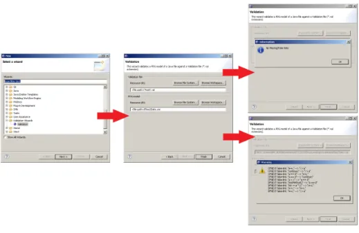
While the validation step is completely performed in ATL, we also developed in Java a graphical wizard to easily select program and specification files (Fig. 3).
Fig. 3. The validation wizard.
5
Conclusions
The full project is available on the SHARE server of the contest[2]. Table 2 presents size information on the implemented transformations. The transforma-tions, beside intrinsic algorithmic complexity, look fairly readable.
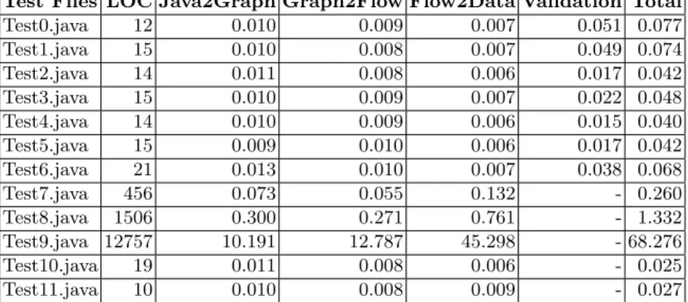
Table 3 shows some preliminary performance evaluation for our solution. It contains the execution times for each ATL transformations on the provided test cases. For the validation step we manually developed complete specification files for Test0-6. The tests have been performed on an environment with the following characteristics: Processor Intel(R) Core(TM) i7 CPU Q 720 @ 1.60Ghz, with 8GB of physical memory, and running Windows 7 Professional 64bit -Service Pack 1. As application environment, tests where performed on the Eclipse Platform version 4.2.1 on top of the OpenJDK Java Virtual Machine version 1.7.0 15. The tests show that the transformations can handle large programs (e.g., Test9.java that contains a single method with more than 12000 LOCs) exhibiting good scalability w.r.t. model size.
9
Transformation LOC Rules Helpers
JavaGetText 214 0 60 Java2Graph 133 12 0 Java2GraphWithVar 183 2 19 Graph2Flow 324 7 28 Flow2Data 92 2 6 Validation 59 0 9
Table 2. Transformation size
Test Files LOC Java2Graph Graph2Flow Flow2Data Validation Total
Test0.java 12 0.010 0.009 0.007 0.051 0.077 Test1.java 15 0.010 0.008 0.007 0.049 0.074 Test2.java 14 0.011 0.008 0.006 0.017 0.042 Test3.java 15 0.010 0.009 0.007 0.022 0.048 Test4.java 14 0.010 0.009 0.006 0.015 0.040 Test5.java 15 0.009 0.010 0.006 0.017 0.042 Test6.java 21 0.013 0.010 0.007 0.038 0.068 Test7.java 456 0.073 0.055 0.132 - 0.260 Test8.java 1506 0.300 0.271 0.761 - 1.332 Test9.java 12757 10.191 12.787 45.298 - 68.276 Test10.java 19 0.011 0.008 0.006 - 0.025 Test11.java 10 0.010 0.008 0.009 - 0.027
Table 3. Execution time per transformation per file (sec).
In conclusion, the case study shows the applicability of ATL to complex trans-formation scenarios in program analysis. The problem can be modularized in a transformation network and concisely represented by using exclusively declara-tive transformation rules and helpers. All the phases are handled by the same transformation language: model-to-model, model refinement, model-to-text, val-idation. The case study represents an interesting illustration of the ATL appli-cation space.
References
1. A. V. Aho, R. Sethi, and J. D. Ullman. Compilers: Princiles, Techniques, and Tools. Addison-Wesley, 1986.
2. AtlanMod. Atl solutions to flowgraphs use-case, 2013. https://is.ieis.tue.nl/ staff/pvgorp/share/?page=Login&bundlename=TTC13.
3. AtlanMod. Atl transformation language home page, 2013. http://www.eclipse. org/m2m/atl/.
4. M. Eysholdt and H. Behrens. Xtext: implement your language faster than the quick and dirty way. In SPLASH, pages 307–309, 2010.
5. F. Jouault and I. Kurtev. Transforming models with ATL. In MoDELS Satellite Events, pages 128–138, 2005.
6. OMG. Object Constraint Language Specification, version 2.0. Object Management Group, June 2005.
7. TTC. Ttc 2013 home page, 2013. http://planet-sl.org/ttc2013/index.php? option=com_content&view=article&id=227&lang=en.
8. TTC. Ttc flowgraphs description, 2013. http://planet-sl.org/community/_/ttc/ ttc2013/cases/Flowgraphs/TTC2013-Flowgraphs-Description.pdf.