HAL Id: hal-01936298
https://hal-mines-albi.archives-ouvertes.fr/hal-01936298
Submitted on 27 Nov 2018
HAL is a multi-disciplinary open access
archive for the deposit and dissemination of
sci-entific research documents, whether they are
pub-lished or not. The documents may come from
teaching and research institutions in France or
abroad, or from public or private research centers.
L’archive ouverte pluridisciplinaire HAL, est
destinée au dépôt et à la diffusion de documents
scientifiques de niveau recherche, publiés ou non,
émanant des établissements d’enseignement et de
recherche français ou étrangers, des laboratoires
publics ou privés.
Valorization of calcium carbonate-based solid wastes for
the treatment of hydrogen sulfide in a semi-continuous
reactor
Marta Galera Martinez, Doan Pham Minh, Ange Nzihou, Patrick Sharrock
To cite this version:
Marta Galera Martinez, Doan Pham Minh, Ange Nzihou, Patrick Sharrock. Valorization of
cal-cium carbonate-based solid wastes for the treatment of hydrogen sulfide in a semi-continuous reactor.
Chemical Engineering Journal, Elsevier, 2019, 360, pp.1167-1176. �10.1016/j.cej.2018.10.169�.
�hal-01936298�
Valorization of calcium carbonate-based solid wastes for the treatment of
hydrogen sulfide in a semi-continuous reactor
Marta Galera Martínez
b, Doan Pham Minh
a,b,⁎, Ange Nzihou
b, Patrick Sharrock
baInstitute of Research and Development, Duy Tan University, Da Nang 550000, Viet Nam
bUniversité de Toulouse, IMT Mines Albi, CNRS UMR 5302, Centre RAPSODEE, Campus Jarlard, Albi F-81013 cedex 09, France
H I G H L I G H T S
•
Valorisation of CaCO3-containing solidwastes for H2S removal from the gas
phase.
•
Design of a triphasic gas/liquid/solid process.•
Crucial importance of H2S dissolutionand dissociation steps in CaCO3
sus-pension.
•
Oxidation of dissolved sulfur species into stable sulfite, sulfate, and thio-sulfate.•
Understanding of the mechanism of H2S removal by this triphasic process.G R A P H I C A L A B S T R A C T Keywords: H2S removal Calcium carbonate Triphasic process Reaction pathway A B S T R A C T
The carbonation of residual brines generates large volumes of carbonate-based solid wastes. Physicochemical properties of these solids are adequate for acid-gas removal. This work studies the valorization of calcium carbonated-based solid wastes for efficient H2S removal from air at low concentrations (≤200 ppmv) in a
three-phase semi-continuous reactor. Synthetic air polluted with H2S was bubbled into the slurry of two different
wastes in a stirred tank to evaluate their effect for H2S removal. The efficiency of H2S removal was kept constant
and could reach up to 98% during 8 h of reaction. Adequate physico-chemical characterization of used sorbents allowed understanding the interaction of sulfide species with sorbent particles. Thus, the reaction pathway for H2S removal was determined. It has been demonstrated that the dissolution of H2S gas at the gas-liquid interface
was then accelerated by high basicity of calcium carbonate-based wastes, followed by the oxidation of dissolved sulfide species. This last was catalyzed by metals and metals oxides which were initially present in the solid wastes. The results obtained demonstrate the possibility to valorize the carbonates which have been precipitated during the carbonation of industrial brines to develop a low cost H2S removal process.
1. Introduction
Hydrogen sulfide (H2S) is an acid gas pollutant released by several
industrial process and agricultural activities. Some of them are petro-leum refineries, natural gas plants, petrochemical plants, coke oven plants, biogas plants and geothermal power plants, pulp and paper
operations, municipal sewers and sewage treatment plants, swine containment and manure-handling operations, food processing plants, tanneries, etc. [1–4]. H2S emissions concentration varies in a large
range from ppmv to volume percentages, which depends on the in-dustrial facility. These emissions are considered as sources of obnoxious odors, perceptible even at very low levels. In fact, the odor threshold of
⁎Corresponding author at: Institute of Research and Development, Duy Tan University, Da Nang 550000, Viet Nam.
H2S can range from 0.5 ppb to 0.3 ppmv [5] that usually causes a
nuisance to neighbors of above-mentioned industrial sites. However, the perception of the odor disappears at higher concentrations (150–200 ppmv[5]) when the gas becomes an extreme health hazard. In fact, the exposure under these concentration levels for some hours is enough to produce severe and irreversible injuries or even death. Thus, smell is not a reliable indicator to recognize the presence of this toxic gas. H2S is also associated with environmental problems. The oxidation
of H2S results in the release of sulfur dioxide (SO2) that is the principal
culprit of acid rain [6]. Even at lower concentration, in the order of dozens to hundreds of ppmv, H2S causes extensive damage in piping
and equipment by corrosion. This leads to a rise in maintenance cost due to repair or/and replacement of affected facilities.
Several methods for the H2S treatment were studied. Standard
technologies are chemical absorption using basic reactants and/or oxidizing agents, the adsorption on activated carbon or other ad-sorbents, and biological processes. The efficiency of these processes has been demonstrated at industrial pilot scale [7–9]. However, these processes still need to be improved, in particular to reduce operational cost and overcome limits of operation conditions. For example, the performance of biofilters depends strongly on the weather conditions because bacteria work under a determined temperature range[10,11]. Several industrial processes (soda-ash process, oil and gas produc-tion, etc.) produce a large volume of residual brines with important amounts of calcium-rich and/or magnesium-rich minerals. The ac-celerated carbonation of these residual brines has been proposed as a method for CO2 sequestration. During this process, called “mineral
carbonation”, CO2reacts with the alkali divalent cations Ca2+and/or
Mg2+and their oxides (CaO and/or MgO) to produce carbonates
par-ticles that are stable at atmospheric conditions[12,13]. These carbo-nates can be valorized for acid gas neutralization in dry or semi-dry flue gas treatment[14,15].
In this work, we show the efficiency of calcium carbonate-based solids, which have been precipitated during the carbonation of residual brines from industrial facilities, in triphasic gas-liquid-solid process for removing H2S from the gas phase. Results obtained are very interesting
from the performance standpoint. This offers the possibility for a future application at large pilot or industrial scale. The advantages of this process are triple: 1) The process uses environmentally-friendly mate-rials taking into account the fact that carbonated-based solids are ob-tained by the stable sequestration of CO2into alkaline residual streams.
This reduces the CO2emissions as the main greenhouse gas. 2) The
carbonated-based solids can be valorized without further pre-treatment. This provides economic benefits. 3) H2S is efficiently removed even at
trace amount under ambient conditions of temperature and pressure from the air atmosphere. Thus this triphasic process is interesting for the treatment of H2S emission from other sources, i.e. H2S in biogas,
natural gas or syngas from pyro-gasification of wastes and/or biomass.
2. Materials and methods 2.1. Materials
Two solid wastes containing mainly calcium carbonate were used. The first one was formed by slow and natural carbonation of residual brines with atmospheric CO2for years. This solid is called thereafter
NPC. The second one came from the artificial carbonation by CO2
bubbling of the similar residual brines. This solid is designated there-after APC. Both solid wastes existed in fine powder form. After drying at room temperature, they are sieved to eliminate the eventual particles larger than 315 µm (less than 1 wt%). No further treatment was done before characterization and use in H2S removal tests. A commercial
calcium carbonate under fine powder form from Fischer Scientific (calcite, CaCO3, > 98%, ref. 10101710) was also used as reference
material.
2.2. Analysis and characterization
Specific surface area was determined using the BET method. Samples were firstly degased in Micrometrics Vacprep 061. The ad-sorption-desorption isotherms were measured with a Micrometrics Tristar II 3020 using nitrogen as gas adsorbate. Scanning electron mi-croscopy coupled with energy dispersive spectroscopy (SEM-EDX) was carried out on a Philips XL30 ESEM apparatus. Particle size distribution of solid powder was measured by laser scattering in a Mastersizer 3000 (Malvern Instruments Ltd) in the range of 0.020–2000 µm. Infrared spectroscopy (IR) was recorded on a Shimadzu FTIR 8400S spectro-meter using a sensitive pyroelectric detector with an L-alanine-doped deuterated triglycine sulfate element. Thermogravimetry analysis (TG) was performed in a TA Instruments SDT Q600 analyzer with a heating rate of 5 °C/min under air flux (100 mL min−1). X-rays diffraction of
solid samples was carried out using a Phillips Panalytical X’pert Pro MPD diffractometer, equipped with a copper X-rays source (Kα of
1.543 Å). The data were collected in the 2θ ranges from 10 to 75° with a step size of 0.0167°. The identification of crystalline phases was based on the JCPDS database. Inductively coupled plasma atomic emission spectroscopy (ICP-AES) was performed using a HORIBA Jobin-Yvon Ultima 2. After test, the suspension was filtered and the liquid phase was analyzed by ion chromatography (ICS3000 DIONEX). Sulfide (S2−)
was measured with an amperometric detector using the column PA1 (250 × 4 mm) and the mobile phase containing 0.1 M NaOH and 0.5 M CH3COONa at the flow rate of 1 mL min−1. Sulfite (SO32−), thiosulfate
(S2O32−) and sulfate (SO42−) ions were measured with a
conducti-metric detector using the column AS11 (250 mm × 4 mm) and the mobile phase containing 30 mM KOH.
2.3. H2S removal test
2.3.1. Reactor and experimental procedure
Tests were carried out in a 250 mL glass stirred reactor (Fig. 1). For a given test, the reactor was firstly purged with dry air flow containing 200 ppmv of H2S (p.a. grade from Air Liquide), which is called
there-after waste air. It was fed to the reactor from the bottom via a porous glass disk. A desired volume of double-distilled water was fed into the reactor, under waste air flow (100 mL min−1) and under stirring
(lim-ited at 600 rpm for the glass reactor used in this work). When the double-distilled water was saturated in H2S, a desired quantity of
sor-bent was added to the reactor to start the H2S removal test.
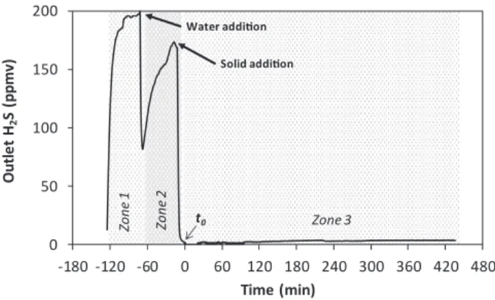
Fig. 2illustrates the different steps of a given H2S removal test in
this work.
InFig. 2, Zone 1 corresponds to the purging step of the reactor with the waste air stream. Zone 2 shows the dissolution of H2S in water, after
filling the reactor with double-distilled water under stirring. When this water was saturated with H2S, sorption test was started by adding a
sorbent to the reactor. The moment for solid addition to the reactor was considered as the zero time of H2S removal test (to, Fig. 2). Zone 3
corresponds to the abatement of H2S by the sorbent added into the
reactor. Typically, in Zone 3, the outlet concentration of H2S abruptly
dropped to zero within less than 2 min. Then, a plateau of outlet H2S
concentration was observed. Within this plateau, the variation of outlet H2S concentration was small (+/−3 ppmv). This concentration was
used to calculate the efficiency of H2S removal (Eq.(1)).
The outlet concentration of H2S was monitored every minute by a
H2S analyzer (Gas Alert QUATTRO, from BW Technologies). All the
experiments were carried out at room temperature and atmospheric pressure. The pH of the suspension was measured at the beginning and at the end of each experiment. Each experiment was carried out for at least 8 h with a semi-continuous process, wherein the volume of the active medium (suspension of solid waste) is practically unchanged, while the waste air continuously passes through the suspension. Each test was repeated at least three times to verify the repeatability. The standard deviation was found to be smaller than 1%.
For the study on the influence of experimental conditions on the removal of H2S, the efficiency of H2S removal is defined by the
fol-lowing equation: = × − Eff (%) 100 [H S][G iH S[]H S]G o G i 2 , 2 , 2 , (1)
where[H S2 ]G i, was the concentration of H2S at the inlet of the reactor
(200 ppmv); and[H S2 ]G o, was the concentration of H2S at the outlet of
the reactor, after reaching the plateau as shown inFig. 2. 2.3.2. Choice of operational parameters
According to the ‘Arrhenius low’, the kinetic constant of a reaction increases as temperature increases. Nevertheless, increasing the perature has a negative effect on gas and solid solubility. As the tem-perature increases, the solubility of a gas decreases. Similarly, the so-lubility of calcite (the major component in the solid wastes) decreases as the temperature increases. In order to promote the mass transfer of the solid and the gas to the liquid phase, low temperatures are re-commended. In this work, the ambient temperature was chosen.
Pressure does not significantly affect the calcite solubility. However, gas solubility is improved at higher pressures but this may result in higher operating and maintenance costs for industrial-scale applica-tions. Thus, atmospheric pressure was chosen in view of the develop-ment of an economically-competitive process.
The optimal gas flow rate was obtained experimentally and set at 100 mL/min for this triphasic reactor[16]. Lower values of the gas flow rate produced preferential flow paths in the gas diffuser (because of the various pore diameter of the glass porous disk), as well as solid de-cantation. For higher values the gas flow rate, the stirring speed should be increased to ensure good dispersion of the waste air in the liquid phase which increases operational cost. Moreover, the impact of the hydrodynamic of the system must be considered. If the stirring speed
and the physicochemical properties of the suspension are supposed constant, an increase in the gas flow makes bubbles diameter larger and consequently the gas-liquid interfacial area a is reduced (Eq.(3)). Also, a high gas flow rate increases the rising speed of bubbles thus the contact time between three phases is reduced. Both have a negative impact on the mass transfer and consequently on the efficiency of the process.
The Eq.(1)could be transformed as follows: =
Eff (RT P Q/H S G2 )NH S2 (2) where NH2Sis the rate of mass transfer of H2S (mol H2S/s) at a given
time t of the H2S removal process, PH2Sis the partial pressure of H2S in
the inlet gas (atm), QGis the volumetric flow rate of the gas (L/s), R is
the universal gas constant (0.0814 atm L/mol K) and T the temperature (K). At the same time, NH2Sis defined as follow[17,18]:
=K a C( −C EV)
H S2 L LE L
N (3)
where KLis the liquid phase mass transfer (m/s), a is the gas-liquid
interfacial area per unit of volume (m2/m3), C
LE is the equilibrium
concentration of H2S in the liquid (mol/m3) and CLis the
concentra-tions of H2S in the bulk of the liquid (mol/m3), E is the enhancement
factor by the solid and V is the suspension volume. Mass transfer parameters as KL and a are dependent of hydrodynamics. In
con-sequence, some hydrodynamic parameters like stirring speed are also considered in the study.
In this work, stirring speed was varied from 200 to 600 rpm, which is the limit of the glass reactor. Other experimental parameters like the residues loading, the suspension volume, and the inlet concentration of H2S were also investigated and are mentioned in the next sections.
3. Results and discussion
3.1. Characterization of calcium carbonate-based solids
Fig. 3shows the particle size distribution of these three sorbents, obtained by the laser scattering (Mastersizer 3000, Malvern Instruments Ltd). Both solid wastes (APC and NPC) had the similar particle size distribution with different populations of particles, rising up to around 400 µm. On the other hand, the commercial calcite from Fisher Scien-tific contained smaller particles (< 35 µm) compared to the solid wastes with a bimodal distribution. In all cases, these solids are fa-vorable for the preparation of aqueous suspension in batch reactor.
Table 1shows that both solid wastes contained calcium carbonate as the main component. Several impurities were also present in these solid wastes. In most of cases, APC contained more impurities than NPC, except for Fe. In addition to these main elements, both APC and NPC contained other minerals at trace amounts including Si (up to 2000 ppm), Al, Zn, Ni and Cu (up to 100 ppm). The presence of chlorine was due to the residual CaCl2and/or NaCl from the brine, which are all
water soluble. NPC contained less chlorine than APC because NPC was landfilled for years and thus, most of chlorine compounds were leached under natural conditions. To check this hypothesis, aqueous
0 50 100 150 200 -180 -120 -60 0 60 120 180 240 300 360 420 480 Outle t H2 S (p p m v) Time (min) Zo n e 1 Solid addition Water addition Zo n e 2 Zone 3 t0
Fig. 2. Example of profile of H2S concentration at the outlet of reactor.
Conditions: gas flow rate of 100 mL min−1, inlet concentration of H 2S of 200
ppmv, 100 mL of suspension, 5 wt% of solid using APC as reactive sorbent, room temperature and pressure.
0 2 4 6 8 10 0.1 1 10 100 1000 V olume (%) Particle size (μm) Commercial calcite NPC APC
suspensions of 10 wt% of APC and NPC were prepared. They were then filtered and the filtrates were analyzed by ICP-AES and ion chromato-graphy (Table 2). The results obtained confirmed that chlorine-con-taining and sulfur-conchlorine-con-taining compounds were more present in APC than in NPC.
The specific surface area (SBET) of the solid before and after
dis-persing in the aqueous solution was analyzed by BET method (Table 3). Both APC and NPC were non-porous solids with low specific surface area. No significant change was observed for NPC after dispersion in an aqueous suspension. For APC, the specific surface area slightly in-creased from 2 to 5 m2g−1, probably due to the leaching of various
species as shown in Table 2. For comparison, the commercial calcite used in this work was also non-porous and had the specific surface area of 2 m2g−1.
XRD analysis (not shown in this paper) showed that calcite was the principal crystalline phase of calcium carbonate[16]. The presence of calcite in NPC and APC is also confirmed by FTIR analysis (Fig. 4). All samples had the characteristic peaks of calcite at 1390, 872 and 712 cm−1. Commercial calcite and NPC showed another small
char-acteristic peak at 848 cm−1. No presence of vaterite was identified
[19]. The peak at 854 cm−1 in APC is characteristic of aragonite, a
polymorph of calcium carbonate. Peaks at 1136 and 1012 cm−1which
were due to the presence of CaSO4-based compounds (anhydrite,
ba-sanite: CaSO4·0.5H2O, and gypsum: CaSO4·2H2O) were also observed
for APC[20].
3.2. Influence of stirring speed
Stirring speed is a hydrodynamic parameter that impacts the mass transfer.Fig. 5shows the dependency of the efficiency on the stirring speed. According to Whitman’s theory, transfer coefficient k is directly proportional to the diffusion coefficient and inversely proportional to the film thickness (k = D/δ). The stirring speed improves the turbu-lence reducingδ and increasing k (for both gas-liquid and solid-liquid transfer). Also, the stirring speed can improve gas-liquid mass transfer by increasing the gas-liquid interfacial area a and the gas hold-up.
Fig. 5shows that APC was more reactive than NPC. Adsorption must be negligible because of the low specific surface of the solids. On the
other hand, the chemical absorption of H2S by species from the
dis-solution of the solid must be considered. The solid disdis-solution rate JBis
described by the Noyes-Whitney equation[17]:
= −
JB k a CS S( Bs CB) (4) where kSis the solid-liquid mass transfer coefficient, aSis the
solid-liquid interfacial area per unit of volume, CBSis the saturated solubility
of the solid in dissolution media and CB is the concentrations of the
solid in dissolution media.
kScan be strongly influenced by stirring speed. It is usually
esti-mated by the Sherwood equation[21]: =
Sh cSc Ren1 n2 (5)
where Sh, Re and Sc are the Sherwood, Reynolds and Schmidt di-mensionless numbers. Sherwood number represents the ratio of the mass transfer rate to the diffusive rate. Schmidt number is the ratio of kinematic viscosity to the diffusive rate. Reynolds number depends on stirring speed. c, n1 and n2 are constants whose values depends on Re. The viscosity and density of the suspensions are involved in the di-mensionless numbers. These properties can be considered similar in both cases. Thus, the influence of the agitation on Re and consequently on kSis similar for both NPC and APC (0.7 10−5≤ kS≤ 3 10−5m/s
depending on the speed agitation).
Considering the fact that all solids particles are under suspension, aS
is not affected by the stirring speed. However, aSand CBsof the two
solid wastes were different from each other. APC was more soluble and had more impurities than NPC. For this reason, APC had a higher dis-solution rate than NPC. In consequence, APC were more available to react with H2S in the liquid media.
3.3. Influence of solid loading and suspension volume
Aqueous suspensions containing various contents of solid wastes were tested for the removal of H2S. In the range of 0.2–9.5 wt% of solid,
the initial pH of the suspensions varied slightly from 9.5 to 9.9. In all cases, the final pH of the suspension was found within the pH range of 8–9 thanks to the omnipresence of CaCO3-based particles which
con-ditioned the pH of the suspension. The effect of ionic strength on gas solubility was assumed negligible.
Fig. 6(a) shows the efficiency of H2S removal as a function of the
solid loading in aqueous suspension. For both solid wastes, the effi-ciency of the system increased with the increase of the solid loading. At 2.5 wt% of solid loading, the reactivity of these solid wastes was found to be higher than that of the commercial calcite. For each solid loading and under the similar operational conditions, APC also showed higher reactivity compared to that of NPC. The highest efficiency of H2S
re-moval reached 95 and 98% at 5 and 10 wt% of APC, respectively. These values were close to the thermodynamic equilibrium of H2S in the
aqueous and the gas phases. The difference on the reactivity of these solid wastes can be explained by their composition and structure. As mentioned before, APC was more soluble than NPC. Thus, the suspen-sion of APC contained more reactive soluble species than that of NPC. These species, in particular metallic cations such as Ca2+, Mg2+, can
catalyze the oxidation of sulfide-based species (S2−, HS−) into sulfur
compounds of higher oxidation state (elemental sulfur for example)
[22]. In addition, carbonate anions (CO32−), which were more
avail-able in the suspension of APC, could also neutralize soluble species of H2S(aq)s. This will be discussed in the next section.
Fig. 6(b) shows the influence of suspension volume of APC on the removal of the H2S. For each solid loading, H2S removal increased with
the increase of suspension volume. However, the effect of suspension volume was less important at high solid loading because the abatement got close to the thermodynamic limit, as mentioned above.
Table 1
Chemical composition of APC and NPC obtained by ICP-AES and TG analyses.
Solid Concentration (g kg−1)
Ca CO32– S Mg Na Fe
APC 357.4 532.0 7.2 2.4 9.9 1.6 NPC 384.2 565.0 1.1 1.3 3.6 3.9
Table 2
Analysis of the major species present in the filtrates of 10 wt% aqueous sus-pensions of APC and NPC.
Solid Concentration (mg kg−1)
Ca Mg Na Cl S
APC 809.2 74.6 482.7 1830.0 286.4
NPC 29.8 5.3 38.2 40.0 30.1
Table 3
Specific surface areas of the raw solids (before) and the solids after dispersing in an aqueous suspension (after).
Solid NPC APC Commercial calcite SBET(m2g−1) Before After Before After Before After
3.4. Influence of the inlet concentration of H2S
The influence of the inlet concentration of H2S on the efficiency of
the process is presented inFig. 7. At the same inlet gas flow rate, the increase of concentration of H2S led to the increase of the rate of H2S
removal (mmol min−1,Fig. 7(a)). According to Henry’s law, the
solu-bility of a gas in a liquid is directly proportional to its partial pressure. As the inlet concentration of H2S increased, the concentration of soluble
H2S increased. This favored the rate of H2S removal.
Fig. 7(b) presents the efficiency of H2S removal as defined by Eq.
(1). We found again that for each inlet concentration of H2S and under
similar reaction conditions, APC was more reactive than NPC. For the suspension of NPC, H2S removal was close to 21% regardless the inlet
concentration of H2S. On the other hand, H2S removal increased
practically linearly with the suspension of APC, explained by the high reactivity of APC suspension.
3.5. Test of long reaction time
Fig. 8(a) shows the efficiency of H2S removal for 7 days test using
the suspension containing only 0.2 wt% of APC. The choice of this di-luted solution was for evaluating the sorbent saturation and/or the loss of reactivity of the suspension within a reasonable time of test (7 days). The first visual observation was the progressive consumption of APC particles. After 7 days of reaction, when the experiment was stopped, the solution was practically transparent. No solid particles were ob-served in suspension. There was only some “grey foam”, which was deposited on the walls of the reactor (Fig. 8(d)).
Fig. 8(a) shows that H2S removal decreased with the reaction time
from around 82% at the first day to around 32% at the last day of test. According to the consumption of APC particles, we suppose that the decrease of H2S removal must be related to the unavailability of
re-active APC particles. APC particles were likely consumed during the test and this consumption was nearly completed after 7 days of test, under the reaction conditions used. After 7 days of test, the accumulated quantity of removed H2S reached 15 mg; the quantity of APC in this test
being 200 mg for preparing 100 mL of suspension of 0.2 wt%. This means that the capacity of APC for H2S abatement according to this
40 50 60 70 80 90 100 600 850 1100 1350 1600 1850 Tr an sm itt anc e (%) Wavenumber (cm-1) 1390 1136 1012 ACP NCP Commercial calcite (A) 55 60 65 70 75 80 85 90 95 100 650 700 750 800 850 900 950 Tr an sm itt anc e (%) Wavenumber (cm-1) 872 854 848 712 700 ACP NCP Commercial calcite (A)
Fig. 4. FTIR spectra of APC, NPC and pure commercial calcite.
0
20
40
60
80
100
0
200
400
600
800
Eff
(
%
)
Stirring speed (rpm)
APC NPCFig. 5. Influence of the stirring speed on the efficiency of H2S removal.
Conditions: Gas flow rate of 100 mL min−1, inlet concentration of H 2S of 200
ppmv, suspension volume of 100 mL, solid loading of 0.2 wt%, room tem-perature and pressure; reaction time of at least 8 h for each test.
0
20
40
60
80
100
0
2
4
6
8
10
Eff
(
%
)
Solid (wt. %)
Commercial calcite NPC APC(a)
50
60
70
80
90
100
0
2
4
6
8
10
Eff
(
%
)
Solid (wt. %)
80 mL 100 mL 160 mL(b)
Fig. 6. (a) Efficiency of H2S removal at different solid loading. Conditions: Gas flow rate of 100 mL min−1, inlet concentration of H2S of 200 ppmv, suspension
volume of 100 mL, stirring speed of 600 rpm, room temperature and pressure. (b) Efficiency of H2S removal as a function of suspension volume of APC. Gas flow rate
of 100 mL min−1, inlet concentration of H
triphasic process can reach at least 75 mg per g of sorbent. This offers a new alternative solution to the conventional sorbents based on carbo-naceous materials [23–25]. For example, Elsayed et al.[23]showed that the sorption capacity of different activated carbons for the removal of H2S in humidified air varied in the range of 4.2–65.9 mg of H2S per g
of sorbent.
“Foam” recovered from the walls of the reactor at the end of test was characterized by FTIR (Fig. 9) and SEM-EDX (Fig. 10). Fig. 9
compares the FTIR spectrum of the fresh APC with that of foam re-covered after 7 days of test. Calcite was still found as the main com-ponent of foam. However, the peak of aragonite at 854 cm−1 was
strongly reduced indicating that calcium carbonate dissolution really took place during the reaction. However, no notable signal was re-corded for sulfur-based compounds by FTIR.
Fig. 10compares SEM images of foam recovered after 7 days of test
0
20
40
60
80
100
0
50
100
150
200
Eff
(
%
)
Inlet concentration of H
2S (ppm
v)
NPC APC(b)
0E+00
2E-04
4E-04
6E-04
8E-04
0
50
100
150
200
mmol
of
H
2S
re
mov
e
d
per
min
Inlet concentration of H
2S (ppm
v)
NPC APC(a)
Fig. 7. Influence of the inlet concentration of H2S. Conditions: Gas flow rate of 100 mL min−1, solid loading of 0.2 wt%, suspension volume of 100 mL, stirring speed
of 600 rpm, room temperature and pressure; (a) rate of H2S removal (mmol min−1); (b) Efficiency of H2S removal (%); reaction time of at least 8 h for each test.
0
20
40
60
80
100
0
1
2
3
4
5
6
7
8
Ef
f
(%
)
Reaction time (days)
(a)
(b)
(c)
(d)
Fig. 8. (a) Efficiency of H2S removal during 7 days of test with APC. Conditions: Gas flow rate of 100 mL min−1, inlet concentration of H2S of 200 ppmv, solid content
of 0.2 wt%, suspension volume of 100 mL, stirring speed of 600 rpm, room temperature and pressure; (b) and (c) and (d): Photos of the reactor wall after one, three and seven days of test, respectively.
40
50
60
70
80
90
100
0
5
8
8
0
0
7
5
0
7
0
0
6
5
0
900
950
Tr
an
sm
it
an
ce
(
%)
Wavenumber (cm
-1)
712 854 848 872 APC Foam recovered after 7 days of testwith those of the initial APC. The initial APC contained particles and agglomerates of various particle sizes (Fig. 10(I)). Large particles of more than 50 µm were usually present in the fresh APC. These large particles were less present in the foam after test (Fig. 10(II)). In addi-tion, particles with high contrast appeared after test (red arrows in
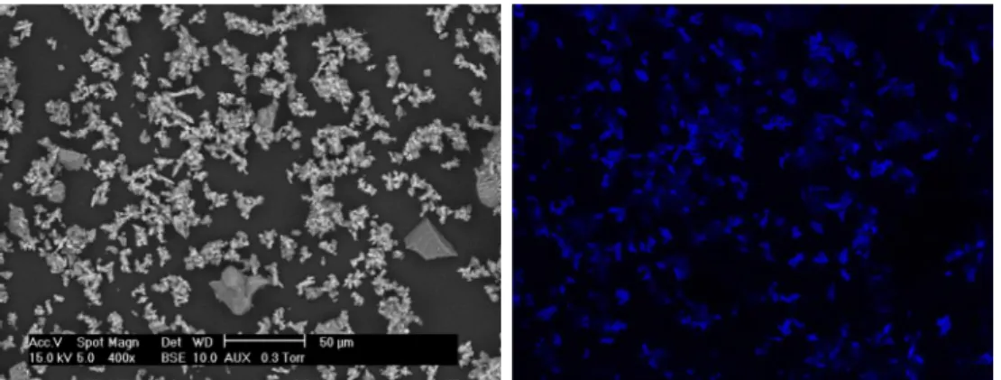
Fig. 10(III)). EDX analysis allowed detecting the presence of sulfur for all the spots analyzed (Spots (a) and (b)). However, the concentration of sulfur was particularly important for the analyses on the particles of high contrast (Spot (c)). Imaging of sulfur was built by EDX analysis on a large zone for a global observation on the localization of sulfur species (Fig. 11). This figure strongly evidences the formation of
sulfur-containing compounds on the surface of the sorbent after test, and al-lowed explaining the abatement of H2S from the waste air inFig. 8.
3.6. Reaction pathway for H2S abatement
We have shown that APC and NPC were active for the removal of H2S from the gas phase by a triphasic gas-liquid-solid process. Their
performance was higher than that of the commercial calcite from Fisher Scientific. Absorption and adsorption phenomena could take place but they did not explain the plateau of the outlet concentration of H2S as
illustrated inFig. 2. Chemical reactions must occur inside the reaction
mixture, as suggested thereafter, in parallel with the “consumption” of calcium carbonate particles by these chemical reactions. The main steps suggested for this process are as follows:
- When the waste air passed through the suspension, the dissolution of gaseous H2S and O2took place (Eqs.(6) and (7)):
⇄
H S2 ( )g H S2 ( )aq (6)
⇄
O2( )g O2( )aq (7)
- When a solid sorbent was added to the reaction mixture, the dis-sociation/dissolution of calcium carbonate and other impurities present in the initial solid sorbent occured (Eqs.(8) and (9)), leading to the formation of soluble metallic cations in solution. Different ions such as Ca2+, Mg2+, Cl−, SO
42−were identified in aqueous
suspension of calcium carbonate-based solids (Table 2): ⇄ + + −
CaCO3( )s Ca( )2aq CO3( )2aq (8)
⇄ + + −
M Ax y s( ) xM( )naq yA( )maq (9)
- In the liquid phase, there was the dissociation and formation of different anions: + ⇄ − + + H S2 ( )aq H O2 HS( )aq H O3 ( )aq (10) + ⇄ + − − + HS( )aq H O2 S2 H O3 ( )aq (11) + − ⇄ − + − H S2 ( )aq CO3( )2aq HS( )aq HCO3( )aq (12) + ⇄ + − − − − HS( )aq CO3( )2aq S( )2aq HCO3( )aq (13)
- Soluble H2S(aq)dissociated and/or reacted with carbonate anions to
form other sulfide species (Eqs.(10)–(13)). The dissociation of hy-drogensulfide (HS−) to form sulfide anion (S2−) according to Eq.
(11)must be negligible at pH around 9 (which was the pH of the suspensions prepared from the three sorbents used in this work), taking into account the second pKa2of H2S in an aqueous solution
(equal to 13 at 25 °C). Thus, the reaction between hydrogensulfide and carbonate anions must be also negligible at pH 9 (Eq.(13)). So, hydrogensulfide (HS−) must be the main sulfide species in the
so-lution at this pH. The resulting soluble sulfide species (S − aq n ( ),
equivalent to the sum of H Saq,HS− andS −
aq aq
2 ( ) ( ) ( )2 ) were oxidized to
higher oxidation states, according to Eq.(14):
+ ⇄ + + +
− − − −
S( )naq O2( )aq S( )s SO3( )2aq SO4( )2aq S O2 3( )2aq (14) - This oxidation could be catalyzed by: 1) soluble metallic cations in solution including Ca2+, Mg2+[22]; and 2) insoluble metals on the
surface of the solid [2,4,22,26]. The presence of sulfite (SO32−),
sulfate (SO42−), and thiosulfate (S2O32−) were confirmed by
ana-lyzing the liquid fraction of the reaction mixture with ionic chro-matography (Fig. 12).
- Finally, the precipitation of sulfur species with metallic cations might also occur to form solid precipitates which could be metals sulfite, metals sulfate or metals thiosulfate:
+ + + + ⇄
+ + − − −
Ca( )2aq M( )naq SO3( )2aq SO4( )2aq S O2 3( )2aq solid precipitates (15)
APC was found to be more efficient than NPC under the same ex-perimental conditions. This can be now confirmed by the higher solu-bility of calcium carbonate present in APC. This calcium carbonate was initially formed by an accelerated process of carbonation and thus was more easily dissolved in an aqueous solution. On the other hand, NPC was formed by the natural atmospheric carbonation process and be-came more difficult to dissolve. So, the suspension of APC contained more carbonate anions (CO32−) and calcium cations (Ca2+), which
were both useful for the dissociation of H2S (Eq.(12)) as well as for the
precipitation of sulfur species (Eq.(15)). The efficiency of the process decreased with the reaction time (Fig. 5) because calcium carbonate particles were progressively consumed. In addition, solid sulfur species were formed and could limit or prevent the contact of calcium carbo-nate particles with sulfide species.
According to the mechanism of H2S abatement in Eqs.(6)–(15), the
dissolved oxygen must play a very important role in this process. Dis-solved oxygen reacted with soluble sulfide species (S −
aq n
( )) to form stable
sulfite (SO32−), sulfate (SO42−), and thiosulfate (S2O32−) species. This
allows the continuous dissolution of gaseous H2S into the suspension
Fig. 11. SEM image (left-hand-side) and imaging of sulfur (right-hand-side, blue color) of the foam recovered after 7 days of test. Images recorded at the same scale.
0
20
40
60
80
100
120
140
0
3
6
9
12
Concentr
ati
on
(ppm)
Time (h)
Sulphite Sulphate ThiosulphateFig. 12. Evolution of the concentration of sulphur species in the liquid phase. Conditions: air flow rate of 100 mL min−1, initial concentration of H
2S in waste
air of 200 ppmv, 100 mL of suspension, 0.2 wt% of solid using APC as reactive sorbent, room temperature and pressure.
and explains the plateau time of H2S outlet concentration inFig. 2. To
confirm this important role of the dissolved oxygen, two experiments were carried out under the same condition using H2S (50 ppmv) in the
synthetic air (20%O2and 80% N2, vol.%) and in pure N2.Fig. 13shows
the results obtained. After the first minutes of reaction wherein the efficiency of H2S abatement was similar to each of two gas matrices, the
efficiency of H2S abatement in the synthetic air reached a plateau time,
but this decreased progressively to zero in pure N2. In fact, the initial
quantity of dissolved oxygen in 200 mL of water fed into the reactor was progressively consumed according to Eq.(14) and it was not re-newed in the case of H2S diluted in pure N2. Thus, Eq.(14)did not
further take place which explained the outlet H2S concentration profile
in the case of H2S diluted in pure N2.
3.7. Comparison with the results reported in the literature
Carbon-based materials (i.e. activated carbon) are considered as references for H2S removal.Table 4compares the performance of APC
and NPC residues with those of carbon-based materials including acti-vated carbon and biochar. Using fixed-bed or fluidized bed reactors, the capacity for H2S abatement of carbon-based materials is generally
below 70 mg of H2S per g of material[2,27–29], in dry or humidified
gas. The residues used in this work showed the comparable reactivity of at least 75 mg of H2S per g of material.
Caustic scrubbing in the aqueous solution using reactants like NaOH, NaClO, NaHCO3is an efficient technology for the removal of
H2S from the gas phase and has the similar operation mode compared to
the reactor design of the present work. As a function of the inlet con-centration of H2S, the feeding of caustic reactants, and the gas flow rate,
the abatement of H2S can reach nearly 100%[29,30]. However, the
cost of these caustic reactants is largely higher (5–10 times) than that of
the residues used in this work[16]. This demonstrates the interest of APC and NPC as the potential materials for H2S removal from the gas
phase using the triphasic G/L/S process. 4. Conclusions
For the first time, a triphasic gas/liquid/solid process was designed for the abatement of H2S from the gas phase using calcium
carbonate-containing residues from industrial activities as reactive sorbents. Solid wastes containing high calcium carbonate contents under powder form could directly be used as sorbent for H2S abatement after a simple
drying at room temperature. At room temperature and ambient pres-sure, this process was found to be very efficient for the abatement of H2S. The dissolution and dissociation of H2S from the gas phase to the
liquid phase was of crucial importance, which allowed increasing the contact time of sulfur species with dissolved oxygen for further oxida-tion into stable sulfite (SO32−), sulfate (SO42−), and thiosulfate
(S2O32−) species. The sorption capacity of APC sorbent could reach at
least 75 mg of H2S per gram of sorbent which is very competitive
compared to that of the conventional sorbents, i.e. activated carbon. The next step of this study would be focused on the trials at large industrial pilot scale with a real waste air from a wastewater treatment plant polluted by H2S.
Acknowledgments
The authors gratefully acknowledge the colleagues at RAPSODEE Research Center (UMR CNRS 5302, France) for their technical help. References
[1] C.F. Cullis, M.M. Hirschler, Atmospheric sulphur: natural and man-made sources,
Atmos. Environ. 14 (1980) 1263–1278.
[2] A. Ros, M.A. Montes-Moran, E. Fuente, D.M. Nevskaia, M.J. Martin, Dried sludges
and sludge-based chars for H2S removal at low temperature: influence of sewage
sludge characteristics, Environ. Sci. Technol. 40 (2006) 302–309.
[3] H. Pham Xuan, D. Pham Minh, M. Galera Martínez, A. Nzihou, P. Sharrock,
Valorization of calcium carbonate-based solid wastes for the treatment of hydrogen
sulfide from the gas phase, Ind. Eng. Chem. Res. 54 (2015) 4915–4922.
[4] K. Kim, S. Asaoka, T. Yamamoto, S. Hayakawa, K. Takeda, M. Katayama, T. Onoue,
Mechanisms of hydrogen sulfide removal with steel making slag, Environ. Sci.
Technol. 46 (2012) 10169–10174.
[5] http://www.atsdr.cdc.gov/toxprofiles/tp114.pdf(accessed on August 06, 2018).
[6] J.H. Seinfeld, S.N. Pandis, Atmospheric Chemistry and Physics: From Air Pollution
to Climate Change, Wiley, New York, 2012.
[7] P.-F. Biard, A. Couvert, C. Renner, P. Zozor, S. Bassivière, J.-P. Levasseur, Hydrogen
sulphide removal in waste water treatment plant by compact oxidative scrubbing in
Aquilair PlusTMprocess, Water Pract. Technol. 4 (2) (2009) wpt2009023.
[8] A. Kerc, S.S. Olmez, Ozonation of odorous air in wastewater treatment plants, J.
Inter. Ozone Assoc. 32 (2010) 199–203.
[9] L. Wu, Y.Y. Loo, L.C. Koe, A pilot study of a biotrickling filter for the treatment of
odorous sewage air, Water Sci. Technol. 44 (2001) 295–299.
[10]H.H.J. Cox, M.A. Deshusses, B.M. Converse, E.D. Schroeder, R. Iranpour, Odor and
volatile organic compound treatment by biotrickling filters: pilot-scale studies at
Hyperion treatment plant, Water Env. Res. 74 (2002) 557–563.
[11]C. Van der Heyden, P. Demeyer, E.I.P. Volcke, Mitigating emissions from pig and
poultry housing facilities through air scrubbers and biofilters: state-of-the-art and
perspectives, Biosystems Eng. 134 (2015) 74–93.
[12]A. Kirchofer, A. Brandt, S. Krevor, V. Prigiobbe, A. Becker, J. Wilcox, Assessing the
potential of mineral carbonation with industrial alkalinity sources in the U.S,
Energy Procedia 37 (2013) 5858–5869.
[13]Q. Liu, M.M. Maroto-Valer, Experimental studies on mineral sequestration of CO2
with buffer solution and fly ash in brines, Energy Procedia 37 (2013) 5870–5874.
[14]V. Filippova, P. Piriou, L. Filippov, J. Yvon, M. Grandjean, Carbonation of residual
brines produced by ammonia-soda process, J. Phys. Conf. Ser. 416 (2013) 012014.
[15]Y. Soong, D.L. Fauth, B.H. Howard, J.R. Jones, D.K. Harrison, A.L. Goodman,
M.L. Gray, E.A. Frommell, CO2sequestration with brine solution and fly ashes,
Ener. Convers. Manage. 47 (2006) 1676–1685.
[16]M. Galera-Martinez, Valorisation des residus carbonates industriels pour le
traite-ment de sulfure d'hydrogene dans les effluents gazeux, University of Toulouse, 2015
(Ph.D. thesis).
[17]E.L. Cussler, Diffusion: Mass Transfer in Fluid Systems, thirrd ed., Cambridge
University Press, New York, 2009.
[18]J.-B. Vilmain, V. Courousse, P.-F. Biard, M. Azizi, A. Couvert, Kinetic study of
hy-drogen sulfide absorption in aqueous chlorine solution, Chem. Eng. Res. Des. 92
(2014) 191–204.
0
20
40
60
80
100
0
60
120 180 240 300 360 420 480
Ef
f
(%
)
t (min)
H
2S in N
2H
2S in Air
Fig. 13. Role of oxygen in the H2S abatement under the similar experimental
condition by using two gas matrices. Conditions: 100 mL de suspension of APC at 0.2 wt%; 600 rpm ; gas flow rate of 100 mL/min ; 50 ppmv d’H2S in N2or air.
Table 4
Example of results on H2S removal using carbon-based materials.
Sorbent Type of reactor
Medium Q (mgH2S/
gsorbent)
Ref. Activated carbon Fixed-bed H2S in dry N2 9 [27]
Char from black liquor carbonization
Fluidized
bed HN22S in humidified
25–70 [28]
Activated carbon Fixed-bed H2S in dry air 5–31 [23]
Char from sludge pyrolysis
Fixed-bed H2S in humidified
air 6–62
[2]
APC and NPC Triphasic G/L/S H2S in dry air scrubbed in suspension of CaCO3-based particles > 75 This work
[19] M. Sato, S. Matsuda, Structure of vaterite and infrared spectra, Z. Kristallogr. 129
(1969) 405–410.
[20] M. Grandjean, L. Filippov, I. Filippova, O. Barres, M. Pelletier, J. Ghanbaja,
Reactivity and valorization of products issued from carbonation of saline waste
solution, Waste Biomass Valorization 4 (2012) 831–841.
[21] H.D. Baehr, K. Stephan, Heat and Mass Transfer, Springer-Verlag, Berlin
Heidelberg, 2011.
[22] J.W. Morse, F.J. Millero, J.C. Cornwell, D. Rickard, The chemistry of the hydrogen
sulfide and iron sulfide systems in natural waters, Earth Sci. Rev. 24 (1987) 1–42.
[23] Y. Elsayed, M. Seredych, A. Dallas, T.J. Bandosz, Desulfurization of air at high and
low H2S concentrations, Chem. Eng. J. 155 (2009) 594–602.
[24] X. Xiao, D.D. Le, L. Li, X. Meng, J. Cao, K. Morishita, T. Takarada, Catalytic steam
gasification of biomass in fluidized bed at low temperature: conversion from live-stock manure compost to hydrogen-rich syngas, Biomass Bioener. 34 (2010)
1505–1512.
[25] M. Hervy, D. Pham Minh, C. Gérente, E. Weiss-Hortala, A. Nzihou, A. Villot, L. Le
Coq, H2S removal from syngas using wastes pyrolysis chars, Chem. Eng. J. 334
(2018) 2179–2189.
[26] H. Tian, J. Wu, W. Zhang, S. Yang, F. Li, Y. Qi, R. Zhou, X. Qi, L. Zhao, X. Wang,
High performance of Fe nanoparticles/carbon aerogel sorbents for H2S removal,
Chem. Eng. J. 313 (2017) 1051–1060.
[27] Y. Xiao, S. Wang, D. Wu, Q. Yuan, Catalytic oxidation of hydrogen sulfide over
unmodified and impregnated activated carbon, Separ. Purif. Technol. 59 (2008)
326–332.
[28]Y. Sun, J.P. Zhang, C. Wen, L. Zhang, An enhanced approach for biochar
prepara-tion using fluidized bed and its applicaprepara-tion for H2S removal, Chem. Eng. Proc. 104
(2016) 1–12.
[29]J. Krischan, A. Makaruk, M. Harasek, Design and scale-up of an oxidative scrubbing
process for the selective removal of hydrogen sulfide from biogas, J. Hazard. Mat.
215–216 (2012) 49–56.
[30]P.-F. Biard, A. Couvert, C. Renner, J.-P. Levasseur, Wet scrubbing intensification
applied to hydrogen sulphide removal in waste water treatment plant, Canad. J.