HAL Id: tel-01323016
https://tel.archives-ouvertes.fr/tel-01323016
Submitted on 30 May 2016HAL is a multi-disciplinary open access
archive for the deposit and dissemination of sci-entific research documents, whether they are pub-lished or not. The documents may come from teaching and research institutions in France or abroad, or from public or private research centers.
L’archive ouverte pluridisciplinaire HAL, est destinée au dépôt et à la diffusion de documents scientifiques de niveau recherche, publiés ou non, émanant des établissements d’enseignement et de recherche français ou étrangers, des laboratoires publics ou privés.
predictive approaches : application to a solar cooling
system for buildings
Eunice Herrera Santisbon
To cite this version:
Eunice Herrera Santisbon. Production-consumption system coordination by hybrid predictive ap-proaches : application to a solar cooling system for buildings. Other. CentraleSupélec, 2015. English. �NNT : 2015CSUP0006�. �tel-01323016�
CentraleSupélec
Ecole Doctorale MATISSEEcole doctorale “Mathématiques, Télécommunications, Informatique, Signal, Systèmes Electroniques”
THÈSE DE DOCTORAT
DOMAINE : STIC Spécialité : Automatique Soutenue le 20 mars 2015 par:Eunice Beatriz HERRERA SANTISBON
Coordination Producteur-Consommateur par des approches prédictives hybrides : application au rafraîchissement solaire des bâtiments
Directeur de thèse : Hervé GUÉGUEN Professeur (CentraleSupélec)
Co-encadrant de thèse : Romain BOURDAIS Professeur adjoint (CentraleSupélec) Composition du jury :
Président du jury : Jean BUISSON Professeur (CentraleSupélec) Rapporteurs : Christian GHIAUS Professeur (INSA de Lyon)
Stéphane GRIEU Professeur (Université de Perpignan) Examinateur : Rudy NEGENBORN Associate Professor (TU Delft)
First of all, my sincere and deepest gratitude to my thesis supervisor, Hervé Guéguen, for giving me the opportunity to be part of the ASH team, for his guidance and persistent support in the development of this thesis. My great gratitude to my co-advisor Romain Bourdais, for his enthusiasm, cooperation and help during these three years.
My special and warm gratitude to my reviewers, Christian Ghiaus and Stéphane Grieu, for the dedicated time to carefully read my research work and because each of their comments and advices have significantly enriched this dissertation. Thanks to Jean Buisson and Rudy Negenborn, for having accepted the invitation to be part of my jury and for their contribution to the improvement of this dissertation.
My gratitude to all the members of the ASH team, because in these three years I learnt some-thing rewarding from each of them. Thanks for their professional and non-professional support. To the CentraleSupélec personnel for its administrative support.
Thanks to my friends in Rennes, for the extraordinary moments, joy and support. My stay would not have been so pleasant without their company.
My very special thanks to my boyfriend Elfrich for his unconditional support, love and for always kindly encouraged me in the most difficult moments.
To my wonderful and inspiring family, for being my pillar of strength, shelter and source of love and for making me feel that distance is not a barrier between us.
Finally, to my sponsors CONACYT and Fundación Pablo García for their financial support to carry out my research project. My gratitude to CentraleSupélec for its financial support to culminate this dissertation.
To guarantee thermal comfort in buildings is directly related to energy consumption. In trop-ical climates, cooling systems for buildings represent one of the largest energy consumers. Therefore, as energy consumption is a major concern around the world, it is important to improve the systems efficiency or seeking new methods of cooling production. A solar cool-ing installation based on the absorption cycle is an alternative to mitigate greenhouse gas emissions and electricity consumption. In contrast to conventional vapor-compression based cooling systems, the absorption cooling production involves a complex system composed of several components as collector panel, storage tank, cooling tower and absorption chiller. Be-sides the sizing of the components, this complex system requires control actions to be efficient as a coordination between hot water storage, cooling water production and consumption is necessary.
The aim of this research is to propose a management approach for a production-consumption energy system based on Model Predictive Control (MPC). The solar absorption cooling sys-tem is seen as part of this production-consumption energy syssys-tem where the hot water storage system is the producer and the chiller-building system is one of the consumers. In order to pro-vide modularity to the control structure, the coordination between the subsystems is achieved by using a partitioning approach where local predictive controllers are developed for each of the subsystems. The consumer controllers compute a set of energy demand profiles sent to the producer controller which selects the profile that better minimize the global optimization cost.
In a first part, the proposed approach is tested on a simplified linear model composed of one producer and several consumers. In a second part, a more complex case is studied. A simplified model of an absorption cooling system is evaluated using the simulation tool TRNSYS. The producer model is no longer linear, instead it is described by a nonlinear hybrid model which increases the complexity of the optimization problem. The simulations results show that the suboptimality induced by the method is low and the control strategy fulfills the objectives and constraints while giving good performances.
Garantir le confort thermique des bâtiments est directement lié à la consommation d’énergie. Dans les zones tropicales, les systèmes de refroidissement représentent l’un des postes les plus gourmands en énergie. Afin de réduire la consommation d’énergie mondiale, il est primor-dial d’améliorer l’efficacité de ces systèmes ou bien de développer de nouvelles méthodes de production de froid. Une installation de refroidissement solaire basée sur le cycle à absorp-tion est une alternative pour réduire les émissions de gaz à effet de serre et la consommaabsorp-tion d’électricité. Contrairement aux systèmes classiques de refroidissement à compression mé-canique, la production de froid par absorption est un système complexe composé de plusieurs composants comme des panneaux solaires, un ballon de stockage, une tour de refroidissement et une machine à absorption. Outre le dimensionnement des composants, ce système complexe nécessite des actions de contrôle pour être efficace parce que la coordination entre le stockage d’eau chaude, la production et la consommation du froid est nécessaire.
Le but de cette thèse est de proposer une structure producteur-consommateur d’énergie basée sur la commande prédictive (MPC). Le système de refroidissement par absorption solaire est considéré comme faisant partie de ce système de production-consommation d’énergie, le système de stockage d’eau chaude est le producteur et la machine à absorption qui distribue de l’eau froide au bâtiment est l’un des consommateurs. Pour que la structure de commande soit modulaire, la coordination entre les sous-systèmes est réalisée en utilisant une approche de partitionnement où des contrôleurs prédictifs locaux sont conçus pour chacun des sous-systèmes. Les contrôleurs des consommateurs calculent un ensemble de profils de demande d’énergie. Ces profils sont ensuite envoyés au contrôleur du producteur qui sélectionne le profil qui minimise le coût global.
Dans une première partie, l’approche proposée est testée sur un modèle linéaire simplifié composé d’un producteur et de plusieurs consommateurs. Dans une deuxième partie, un cas plus complexe est étudié. Un modèle simplifié d’un système de refroidissement à absorption est évaluée en utilisant l’outil de simulation TRNSYS. Le modèle de production n’est plus linéaire, il est décrit par un modèle non linéaire hybride qui augmente la complexité du problème
méthode est faible. De plus, la performance de l’approche atteint les objectifs de commande tout en respectant les contraintes.
Symbols
A Total collector array gross area [m2] a0 Solar collector intercept efficiency [−]
a1 Solar collector efficiency slope [kJ hr−1m−2K−1 ]
a2 Solar collector efficiency curvature [kJ hr−1m−2K ]
b Number of energy profiles sent to the producer [−] c Specific heat of the fluid [kJ kg−1K−1]
ctrl Binary control signal [−]
Cmin Minimum capacity rate of the fluids entering the heat exchanger [kJ K−1hr−1]
D1 Producer subsystem disturbances vector [−]
D2 Consumer subsystem disturbances vector [−]
E Energy stored [kW hr]
g,max Maximum value of the g variable [−]
g,min Minimum value of the g variable [−]
g,nominal Nominal value of the g variable [−]
IT Total radiation on collector tilted surface [kJ hr−1m−2]
IT s Total radiation on building’s wall oriented to the south [kJ hr−1m−2]
IR U1 Index to quantify the auxiliary energy use [kW h]
IR Pcsm Index to quantify the total energy consumption [kW h]
I4U(i)
2 Index to quantify the number of switch on/off changes [−]
IU(i)
2 Index to quantify the switch on events [−]
IY(i)
2 Index to quantify the average of the building temperature deviation [°C]
Itime Index to quantify the simulation time [min]
¯
J2 Set of b consumer optimization costs [−]
J1 Producer subsystem optimization cost [−]
J2 Consumer subsystem optimization cost [−]
Symbols
Jg Calculated optimization cost using b lower than the centralized case [−]
Jgopt Calculated optimization cost of the centralized case [−]
Jt Set of chiller-building optimization costs [−]
Jth One element of the set Jt[−]
m Number of consumers [−]
max(x) Maximum value of vector x [−] ˙
m1 Diverter outlet fluid mass flow rate to the tank cold side [kg hr−1]
˙
m2 Diverter outlet fluid mass flow rate to the mixing valve [kg hr−1]
˙
mch Fluid mass flow rate in the chiller evaporator circuit [kg hr−1]
˙
mh Fluid mass flow rate of the heat exchanger-tank loop [kg hr−1]
˙
ml Fluid mass flow rate in the chiller generator circuit[kg hr−1]
˙
ms Fluid mass flow rate of the heat exchanger-collector loop [kg hr−1]
Nh Prediction horizon [−]
ON Set of b chiller optimal control inputs [−]
On Switch control variable of the building cooling system[−] Q Weighting coefficient [−]
˙
Qaux Rate of energy input by the heating element [kJ hr−1]
˙
Qcool Cooling power of the solar absorption cooling system [kJ hr−1]
˙
Qhot Heating power of the solar absorption cooling system [kJ hr−1]
˙
Qs Rate of energy transfer in the collector [kJ hr−1]
Pcoo Consumption power of simplified model [kJ hr−1]
Pcsm Cooling power of simplified model[kJ hr−1]
Pelc Auxiliary electric power of simplified model[kJ hr−1]
Pese Storage power of simplified model [kJ hr−1]
Psol Solar gains of simplified model[kJ hr−1]
Tchr Temperature of the fluid entering the chiller evaporator circuit [◦C]
Tchs Temperature of the fluid entering the cooling ceiling of the building [◦C]
Text Exterior temperature [◦C]
Th Temperature of the fluid entering the storage tank from the heat source [◦C]
Ti Collector inlet temperature [◦C]
Tk Temperature of the kth tank segment [◦C]
Tl Outlet water temperature of the chiller generator [◦C]
To Mixing valve outlet temperature [◦C]
Symbols
Ts Collector outlet temperature [◦C]
Tsbg Set-point temperature of the building [◦C]
Tset Set-point temperature demanded by the chiller generator circuit [◦C]
Twbp Water boiling point temperature [◦C]
tk Solar cooling plant sampling time [hr]
¯
U2 Set of b optimal control inputs [−]
U1 Producer subsystem controlled variables vector [−]
U2 Consumer subsystem controlled variables vector [−]
V Volume of the stratified storage tank[m3] W21 Interacting variable between subsystems [−]
X1 Producer subsystem state vector [−]
X2 Consumer subsystem state vector [−]
x State vector of the building state-space model [−] ˆ
x Estimated vector of the building state-space model [−] ¯
x Average of vector x [−]
Yr Temperature set-point variable [◦C]
α Optimized variable associated with the additional flow rate [−]
δ Occupancy profile [−]
γ Diverter control function [−]
4 ˙ml Additional flow rate sent to the chiller [kJ hr−1]
4t Prediction model sample time [hr] ε Heat exchanger effectiveness [−] η Solar collector efficiency [−]
Π Set of consumers energy demand profiles [−] πh One element of the set Π [−]
ρ Water density [kg m−3]
% Solar absorption cooling power constant effectiveness [−]
σ Switching mode [−]
σsd Standard deviation [−]
ς Consumption power constant effectiveness [−]
Abreviations
ANN Artificial neural network
BLR Based logic rules
CCS Cooling consumption system
CFCs Chlorofluorocarbons
COP Coefficient of performance
CPS Cooling production system
DMPC Distributed Model Predictive Control
ESE Energy storage element
EPA Environmental Protection Agency
GA Genetic algorithm
GPC Generalized Predictive Control
HCFCs Hydrochlorofluorocarbons
HMPC Hierarchical Model Predictive Control HVAC Heating, ventilation, and air conditioning MINLP Mixed Integer Nonlinear Problem
MPC Model Predictive Control
NLMPC Non-linear Model Predictive Control
OECD Organization for Economic Cooperation and Development
PMV Predicted mean vote
SHWS Solar powered hot water storage SMPC Stochastic Model Predictive Control
1 Commande prédictive des systèmes de production-consommation d’énergie 1
1.1 Contexte . . . 1
1.2 Le rafraîchissement solaire des bâtiments . . . 2
1.2.1 Description générale . . . 2
1.2.2 Conditions d’exploitation . . . 3
1.2.3 Formalisation du problème . . . 4
1.2.3.1 Le producteur d’énergie . . . 5
1.2.3.2 Le consommateur d’énergie . . . 5
1.3 Approche par commande prédictive pour le management d’un système de production-consommation d’énergie . . . 6
1.3.1 Modélisation . . . 6
1.3.2 Contrôle-commande . . . 7
1.3.3 Résultats . . . 8
1.4 Commande prédictive appliquée à un modèle TRNSYS . . . 9
1.4.1 Cas d’étude . . . 9
1.4.2 Résultats . . . 10
1.5 Conclusions et perspectives . . . 12
2 Introduction 13 2.1 Motivation of the thesis . . . 13
2.2 Contributions of the thesis . . . 14
3 Background 17
3.1 Cooling systems in buildings . . . 17
3.1.1 The vapor-compression based cooling unit . . . 18
3.1.2 Economical and environmental aspects of the vapor-compression cooling unit . . . 18
3.1.3 The absorption cooling unit . . . 20
3.2 The solar absorption cooling installation . . . 23
3.2.1 Presentation . . . 23
3.2.2 Impact of the sizing of components on the absorption cooling system performance and efficiency . . . 25
3.2.3 Operating conditions of the solar absorption cooling system . . . 26
3.2.4 Advanced control strategies for solar absorption cooling systems . . . . 30
3.2.5 Summary: objectives, controlled and manipulated variables of the solar absorption cooling installation . . . 33
3.3 MPC approaches for thermal comfort in buildings . . . 35
3.4 Conclusions . . . 39
4 Energy production-consumption problem statement 41 4.1 Motivation . . . 41
4.2 The solar absorption cooling system as part of an energy production-consumption system . . . 42
4.2.1 The energy producer . . . 43
4.2.2 The energy consumer . . . 45
4.3 Conclusion . . . 46
5 Predictive and interactive controllers for a producer-consumer system 49 5.1 The producer-consumer system . . . 49
5.1.1 Generalized model . . . 50
5.1.2 Simplified model . . . 51
5.2 Logic rule-based control approach . . . 54
5.3.1 Global optimization problem: a multi-objective criterion . . . 57
5.3.2 Proposed MPC architecture . . . 59
5.3.2.1 Consumer optimization problem . . . 59
5.3.2.2 Producer optimization problem . . . 63
5.3.2.3 Control strategy algorithm . . . 64
5.3.3 Performance indexes . . . 65
5.3.4 Simulation results . . . 66
5.3.4.1 Prediction horizon Nh impact . . . 67
5.3.4.2 About the suboptimality of the proposed control strategy . . 72
5.4 Conclusions . . . 78
6 Application to a TRNSYS test case 79 6.1 The solar absorption cooling system . . . 80
6.1.1 System description . . . 80
6.1.2 Modeling . . . 81
6.1.2.1 Producer: SHWS system . . . 82
6.1.2.2 Consumer: chiller-building system . . . 85
6.1.3 Operating conditions of the solar cooling system . . . 86
6.2 Logic rule-based control approach . . . 87
6.3 Mixed MPC-LRBC strategy for the solar cooling system . . . 91
6.3.1 The chiller-building system controller . . . 91
6.3.2 The SHWS system controller . . . 92
6.3.2.1 From the producer generalized model to the SHWS system model . . . 92
6.3.2.2 Prediction of disturbances . . . 93
6.3.2.3 Initial optimization problem . . . 94
6.3.3 Control architecture . . . 97
6.3.4 Simulation results . . . 97
6.4 Model Predictive Control approach . . . 101
6.4.1.1 Consumer controller structure . . . 103
6.4.2 Producer optimization problem . . . 104
6.4.3 Proposed MPC architecture for the solar cooling system . . . 105
6.4.4 Simulation results . . . 105
6.5 Quantitative analysis and conclusions of the proposed control strategies . . . 111
7 Conclusions and perspectives 113 7.1 Conclusions . . . 113
7.2 Perspectives . . . 117
Appendix A Model and control parameters 119
Appendix B TRNSYS simulation model 125
Appendix C Building model identification 131
List of Figures 135
List of Tables 139
Commande prédictive des systèmes de
production-consommation d’énergie
1.1
Contexte
Dans les zones tropicales, les systèmes de rafraîchissement des bâtiments sont indispensables afin de maintenir le confort thermique des occupants. La manque de confort thermique peut perturber la productivité et la santé des occupants. Une faible productivité se manifeste par la manque de concentration, la somnolence, et l’absentéisme du travailleur (Kreith and West, 1997). De plus, les systèmes de rafraîchissement sont également utilisés pour le rendement et l’efficacité d’un processus de fabrication ou pour maintenir la qualité et le cycle de vie d’un produit stocké (Ameen,2006).
De nos jours, les machines de climatisation à compression mécanique sont les systèmes les plus fréquemment utilisés mondialement. Ces systèmes fonctionnent avec l’électricité et donc émettent des gaz à effet de serre. Comme la consommation électrique devient de plus en plus élevée, il est nécessaire d’optimiser leur utilisation ou bien les remplacer par des systèmes alternatifs de climatisation.
Malgré leur faible coefficient de performance (COP), l’utilisation des machines frigorifiques à absorption solaire est une solution attractive pour réduire la consommation électrique des bâtiments lorsque la source d’énergie est gratuite (énergie solaire, chaleur résiduelle). D’autre part, le cycle à absorption solaire est particulièrement intéressant car les charges de refroidisse-ment coïncident avec la puissance solaire disponible (Li and Sumathy,2001).
Contrairement au système de climatisation à compression mécanique, une installation de rafraîchissement solaire nécessite généralement plusieurs composants pour fonctionner (pan-neau solaire, échangeur de chaleur, ballon de stockage, tour de refroidissement). En effet, la machine à absorption requiert trois sources d’énergie à différentes températures. Afin de max-imiser le rendement global de l’installation, il est nécessaire de coordonner le fonctionnement
des composants. De plus, la production d’énergie doit être synchronisée avec le besoin de climatisation du bâtiment.
L’objectif de cette thèse est de proposer une méthode de coordination entre un producteur d’énergie et un ou plusieurs consommateurs qui permette de maximiser l’utilisation de la source solaire tout en assurant le confort thermique des occupants. Cette méthode est basée sur des contrôleurs prédictifs pour le producteur et les consommateurs. Dans cette approche décentralisée, une interaction entre le contrôleur du producteur et les contrôleurs des consom-mateurs est mise en œuvre afin de s’approcher de la solution optimale globale.
1.2
Le rafraîchissement solaire des bâtiments
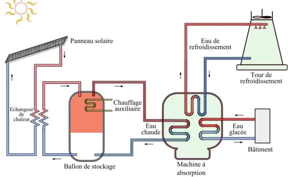
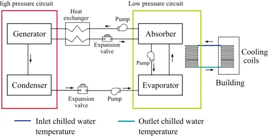
1.2.1 Description généraleLa figure 1.1 représente une installation de rafraîchissement solaire typique composée prin-cipalement d’un panneau solaire, d’un ballon de stockage d’eau chaude, d’un échangeur de chaleur, d’une machine à absorption et d’une tour de refroidissement. La chaleur captée par le panneau solaire est transférée au ballon de stockage à travers l’échangeur de chaleur. Le ballon de stockage fournit l’eau chaude nécessaire pour le fonctionnement de la machine frigorifique à absorption. Le chauffage auxiliaire est utilisé lorsque la source solaire est faible.
Ballon de stockage Echangeur de chaleur Chauffage auxiliaire Eau chaude Panneau solaire Bâtiment Eau de refroidissement Eau glacée Machine à absorption Tour de refroidissement
Figure 1.1: Une installation de rafraîchissement solaire typique.
un plafond rafraichissant. L’eau glacée est produite à partir du cycle à absorption qui est composé de quatre éléments : l’absorbeur, le concentrateur, le condenseur et l’évaporateur. Une solution saline qui circule parmi les éléments est soumise à différentes températures et pressions ce qui entraîne des changements de concentration. La tour de refroidissement a pour fonction d’évacuer la chaleur extraite dans l’évaporateur et le condensateur.
1.2.2 Conditions d’exploitation
Pour faire fonctionner la machine à absorption et respecter les conditions de sécurité de l’installation, une série de conditions sont requises:
• La température de sortie du panneau solaire doit être supérieure à une valeur de consigne de température qui dépend soit de la température de l’eau fournie à la machine à absorption, soit de la température de l’eau qui circule du ballon de stockage vers le panneau solaire.
• Il est nécessaire de surveiller la température de sortie du panneau solaire lorsque le rayonnement solaire est important et qu’il n’y a pas de demande, car le fluide calo-porteur peut monter jusqu’à la température de stagnation. Celle-ci est la température du fluide caloporteur au repos dans le panneau solaire qui continue à se chauffer par l’ensoleillement incident (Jabbour,2011).
• La machine à absorption doit être arrêtée si la source de chaleur ne fournit pas la température requise par le circuit du concentrateur afin d’éviter un fonctionnement en dehors des conditions nominales.
• La source d’appoint électrique peut être activée lorsque le rayonnement solaire est faible. • Comme le stockage d’eau glacée ne fait pas partie de l’installation considérée, une syn-chronisation est nécessaire entre la disponibilité de l’eau chaude, la production d’eau glacée et la demande de climatisation.
Dans le but de respecter ces conditions, les variable suivantes sont pilotables :
• Les débits des pompes du circuit solaire, c’est-à-dire, les débits d’eau qui circulent entre le panneau solaire, échangeur de chaleur et ballon.
• La puissance du chauffage d’appoint.
• Les températures d’entrée au concentrateur, condenseur et évaporateur. • Le débit et la température délivrés à la zone climatisée.
Il résulte de ce qui précède qu’il est indispensable de mettre en œvre un mécanisme de gestion globale afin de respecter les conditions d’exploitation en utilisant de manière optimale les ressources énergétiques (solaire et électrique).
1.2.3 Formalisation du problème
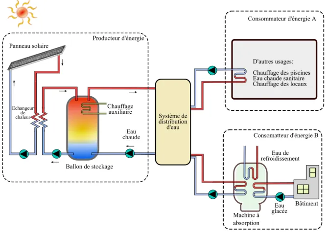
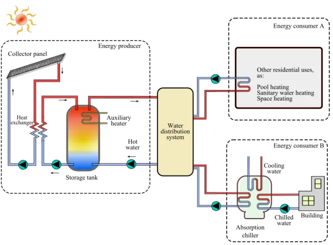
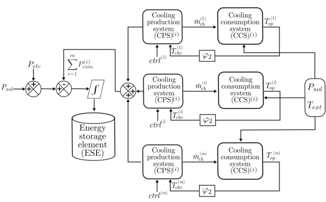
L’installation de refroidissement solaire peut être vue comme une partie d’un système de production-consommation d’énergie. La figure 1.2 représente la structure proposée de ce sys-tème. Il est composé d’un producteur qui fournit de l’eau chaude à plusieurs consommateurs connectés par le moyen d’un système de distribution d’eau. L’un de ces consommateurs est composé de la machine à absorption qui fournit de l’eau glacée à l’espace climatisé.
Bâtiment' Machine'à absorption Ballon'de'stockage Echangeur de chaleur Chauffage auxiliaire Eau'de refroidissement Eau chaude' Panneau'solaire Système'de distribution d'eau Eau glacée Consomatteur'd'énergie'B Consommateur'd'énergie'A D'autres'usages: ' Chauffage'des'piscines Eau'chaude'sanitaire Chauffage'des'locaux Producteur'd'énergie
Figure 1.2: Système de production-consommation d’énergie.
Cette thèse propose une gestion globale à un niveau haut du système en considérant un con-trôle modulaire, c’est-à-dire, des concon-trôleurs prédictifs indépendants pour le producteur et les consommateurs qui intègrent un mécanisme d’interaction. Dans cette gestion, le producteur est vu comme un fournisseur d’eau chaude à une température et débit de consigne lorsqu’une demande de consommation est requise par un ou plusieurs consommateurs.
La gestion proposée du système requiert des mécanismes d’interaction entre le producteur et les consommateurs afin de minimiser la dégradation de la solution optimale qui pourrait être obtenue en utilisant une approche centralisée. Cependant, les mécanismes d’interaction de l’approche proposée restent simples du fait que les interactions entre les consommateurs ne sont pas considérées.
1.2.3.1 Le producteur d’énergie
Ce sous-système est composé d’un panneau solaire, un échangeur de chaleur et un ballon de stockage d’eau chaude. Il doit fournir de l’eau chaude à une température et un débit fixes aux consommateurs. Les températures des composants doivent être contrôlées afin d’assurer la protection du système et de délivrer l’eau chaude à la température désirée aux consommateurs. Le modèle du producteur est obtenu à partir des modèles des composants. Le ballon de stockage est représenté par un jeu d’équations différentielles dont l’expression change en fonc-tion du sens du flux. Un modèle hybride associant dynamique continue et événementielle est alors utilisé. La représentation mathématique du panneau solaire et de l’échangeur de chaleur est faite par des modèles statiques proposés par l’outil de simulation thermique TRNSYS (TRNSYS17-Documentation,2012).
1.2.3.2 Le consommateur d’énergie
Afin d’illustrer la gestion proposée du système de production-consommation d’énergie, un type de consommateur d’énergie a été choisi : une machine à absorption qui fournit de l’eau glacée à un bâtiment en utilisant un plafond rafraichissant. Un bâtiment de taille moyenne et une machine à absorption de petite puissance sont considérés pour l’étude.
Compte tenu du temps de réponse du bâtiment, la réponse transitoire de la machine à ab-sorption n’est pas prise en compte. Par conséquent, un modèle statique est considéré et son fonctionnement est limitée aux conditions nominales. A partir de ce choix et comme la tem-pérature d’entrée au concentrateur est fixe, le contrôleur peut agir uniquement sur la marche et l’arrêt de la machine.
L’objectif du contrôleur du consommateur d’énergie est de maintenir le confort thermique dans le bâtiment pendant les périodes d’occupation. La variable manipulée est un signal de commande discret qui met en marche ou à l’arrêt la machine à absorption. Le consommateur d’énergie est représenté par un modèle d’état linéaire qui décrit la dynamique du bâtiment et du plafond rafraichissant.
1.3
Approche par commande prédictive pour le management
d’un système de production-consommation d’énergie
1.3.1 Modélisation
La figure 5.2 représente le système de production-consommation d’énergie. Le producteur est un sous-système décrit par une dynamique non linéaire hybride et ses variables de commande U1(k) sont les débits des pompes du circuit solaire et la puissance du chauffage auxiliaire.
Le consommateur d’énergie est représenté par un système dynamique avec une entrée de commande binaire U2(k). L’entrée de commande du consommateur est la marche/arrêt de la
machine à absorption.
Energy producer
Energy consumer
Energy demand Binary control
input Continous
control inputs
Disturbances Disturbances
Figure 1.3: Représentation d’un système de production-consommation d’énergie. Le producteur d’énergie S1 est décrit par un modèle non linéaire hybride de la forme
X1(k + 1) = f1σ(k)(U1(k), W21(k)) (1.3.1)
σ(k) = σ(U1(k), W21(k)) (1.3.2)
où U1(k) = [X1(k), U1(k), D1(k)]. U1(k) ∈ Rm1 est le vecteur de variables de commande et
D1(k) ∈ Rp1 est le vecteur de perturbations. W21(k) ∈ Rq1 est le vecteur de variables de
couplage entre les sous-systèmes.
Le producteur S1 est soumis à des contraintes d’entrée et de sortie :
H1σ(k)(U1(k), W21(k)) ≤ 0 (1.3.3)
X2(k + 1) = f2(X2(k), U2(k), D2(k)) (1.3.4)
Y2(k) = H2(X2(k)) (1.3.5)
W21(k) = G(X2(k), U2(k)) (1.3.6)
U2(k) ∈ {0, 1} est la variable de commande discrète et D2(k) ∈ Rp2 est le vecteur de
pertur-bations. Y2(k) ∈ Rr2 est le vecteur de sortie.
Le consommateur S2 est soumis à des contraintes d’entrée et de sortie :
H2(U2(k)) ≤ 0 (1.3.7)
où U2(k) = [X2(k), U2(k), D2(k)].
1.3.2 Contrôle-commande
Comme le système de production-consommation d’énergie est soumis à des contraintes d’entrée et de sortie, à des perturbations et à des conditions d’exploitation, la gestion globale du sys-tème peut être effectuée en considérant une approche par commande prédictive (MPC, voir par exempleCamacho and Bordons(2004)). En effet, cette approche de contrôle-commande est caractérisée par sa capacité à gérer les contraintes, les fonctions d’optimisation multiobjec-tif et les dynamiques linéaires et non linéaires. Le principe du MPC est de calculer les entrées futures du système sur un horizon fixe en minimisant une fonction de coût. Un modèle de prédiction du système est nécessaire, ainsi qu’une prédiction adéquate des perturbations. La gestion globale du système est réalisée en considérant des contrôleurs prédictifs pour le producteur et les consommateurs d’énergie. L’objectif de cette approche est de minimiser le coût de fonctionnement tout en garantissant les conditions d’exploitation et les besoins de consommation.
L’objectif de contrôle du producteur est de minimiser l’énergie électrique auxiliaire en res-pectant les contraintes. En ce qui concerne le consommateur, l’objectif du contrôleur est de maintenir le confort thermique du bâtiment en tenant compte des restrictions de fonction-nement de la machine à absorption. Les contrôleurs des consommateurs proposent plusieurs profils de demande d’énergie au contrôleur du producteur. Celui-ci va tester toutes ces straté-gies possibles et choisir la meilleure combinaison.
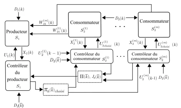
La figure 1.4 représente l’architecture proposée pour la gestion globale du système de production-consommation d’énergie. Une description détaillée de l’algorithme est décrit ci-dessous.
. . .
Contrôleur du consommateur Producteur Consommateur. . .
choisi h k ( ) D1 S2(1) k ( ) k ( ) Jt( )k , k ( ) W21(1) W21(m)( )k X2(1)( )k X(m)2 ( )k D1( )k D2( )k S2(m) S2(1) U 2 (1) choisi ( )k U2 (m) choisi ( )k S1 S1 U 2 (m) k ( -1) Contrôleur du producteur Consommateur Contrôleur du consommateurFigure 1.4: Architecture proposée pour le contrôle-commande du système de production-consommation d’énergie.
1. Les contrôleurs des consommateurs calculent la matrice Π(k) composée par bmprofils de
demande d’énergie sur l’horizon de prédiction Nh à partir du vecteur d’état de chaque
consommateur X(i)
2 (k)i=1,...,m, les entrées de commande antérieures U2(i)(k − 1)i=1,...,m,
et la prédictions des perturbations D2(k)sur l’horizon de prédiction Nh. Cette matrice
est envoyée au contrôleur du producteur d’énergie.
2. Le contrôleur du producteur calcule bm optimisations linéaires selon la matrice Π(k)
et en prenant en compte le vecteur d’état du producteur X1(k) et les prédiction des
perturbations D1(k)sur l’horizon de prédiction Nh.
3. Le contrôleur du producteur choisit le profil qui a le coût le plus bas.
4. Le contrôleur de producteur envoie le premier élément du vecteur de commande U1(k)
au producteur et communique aux contrôleurs de consommation d’énergie quel est le profil d’énergie qui a été choisi. Les contrôleurs des consommateurs envoient le premier élément du vecteur de commande U(i)
2 (k)qui est associé au profil choisi πh(k).
5. L’algorithme redémarre au pas d’échantillonnage k + 1. 1.3.3 Résultats
La stratégie par commande prédictive est testée sur un modèle simplifié d’un système de production-consommation d’énergie. Le producteur est un modèle linéaire qui représente un
stockage d’énergie solaire et électrique et chaque consommateur est composé d’une machine à absorption et d’un espace à climatiser. Il est représenté par un modèle linéaire. Afin de comparer les résultats de la stratégie, une approche de contrôle-commandé basée sur des contrôleurs tout ou rien pour le producteur et les consommateurs est mis en œuvre. Les résultats des deux stratégies sont résumés dans le Tableau 1.1.
Table 1.1: Tableau comparatif des stratégies de contrôle-commande
Système de production-consommation d’énergie Caractéristiques Difficultés Un producteur et plusieurs
consommateurs. Des modèles linéaires pour les sous-systèmes.
Dépendance bilinéaire entre les consommateurs et producteur. Signal
de commande binaire pour les consommateurs. Les stratégies de contrôle-commande
Caractéristiques Avantages Inconvénients Stratégie
basée sur des algorithmes tout ou rien Contrôleurs d’hystérésis pour le producteur et les consommateurs. Optimisation non nécessaire. Mise en œuvre
facile. Nombreux marche/arrêt de la machine à absorption. Energie auxiliaire consommée élevée. Approche MPC: Profils optimaux Approche MPC linéaire et hybride. La matrice de demande d’énergie envoyée au producteur
est composée des profils minimisant le coût d’optimisation.
La marche/arrêt de la machine à absorption est
minimisé. L’usage de l’énergie auxiliaire est adapté à la
consommation. Les contraintes du producteur et des consommateurs sont respectées. La complexité de calcul augmente de façon exponentielle avec le nombre de consommateurs. La solution obtenue est
sous-optimale en comparaison avec le cas
centralisé.
1.4
Commande prédictive appliquée à un modèle TRNSYS
1.4.1 Cas d’étudeLa stratégie de contrôle-commande proposée est testée sur un modèle plus complexe développé dans l’outil de simulation TRNSYS. L’objectif de cette étude est d’évaluer la performance de la stratégie lorsque la complexité du système à commander augmente. Plus précisément, le
producteur n’est plus représenté par un modèle linéaire. Ce sous-système est un producteur d’eau chaude qui intègre les éléments suivants : panneau solaire, échangeur de chaleur et ballon de stockage d’eau chaude. Comme la complexité du producteur augmente, le modèle de prédiction n’est plus linéaire, il est représenté par un modèle non linéaire hybride. Par conséquent, la résolution du problème d’optimisation est bien plus difficile.
Les objectifs de la stratégie en ce qui concerne le contrôleur du producteur sont le respect des conditions d’exploitation du système et la minimisation de l’usage du chauffage d’appoint. Les températures de sortie des éléments doivent rester en dessous de la température d’ébullition de l’eau et lorsque la machine à absorption marche, la température de l’eau qui circule du ballon à la charge doit être au dessus de la température nominale de la machine à absorption. Les variables de commande de ce sous-système sont les débits des pompes.
Comme dans la Section 1.3, le consommateur d’énergie s’agit d’une machine à absorption qui délivre de l’eau glacé à un bâtiment par le moyen d’un plafond rafraichissant. Les objectifs du contrôleur sont de garantir le confort thermique des occupants en minimisant le nombre de marche/arrêt de la machine à absorption et son usage.
Dans cette étude, les modèles de prédiction et de simulation sont différents. Le modèle de prédiction du consommateur d’énergie reste inchangé, c’est-à-dire, une représentation linéaire est utilisé. Le modèle de simulation est développé sur l’outil de simulation thermique TRN-SYS. Le modèle thermique du bâtiment considéré pour l’étude est composé de deux zones avec une surface globale de 192 m2. La surface exposée au sud (120 m2) est la zone à climatiser.
Comme l’algorithme de contrôle-commande est développé sur MATLAB, un interaction entre les deux outils de simulation est mise en place en utilisant un élément spécifique de la librairie TRNSYS.
1.4.2 Résultats
Afin de comparer les résultats de la stratégie par commande prédictive, deux algorithmes de contrôle-commande ont été développés. La première stratégie utilise des contrôleurs tout ou rien tant pour le producteur que pour le consommateur. Les débits des pompes du producteur sont à débit constant lorsque la température de sortie du panneau solaire est plus grande que celle qui circule du ballon à l’échangeur de chaleur. De la même manière, le chauffage d’appoint est activé à puissance constante si le rayonnement solaire est faible et s’il y a une demande d’eau chaude par la machine à absorption. En ce qui concerne le consommateur, la température intérieure du bâtiment est contrôlée par hystérésis en mettant en marche ou à l’arrêt la machine à absorption. La seconde stratégie correspond à un contrôleur prédictif pour le producteur qui optimise l’usage du chauffage d’appoint et les débits de pompes. Le contrôleur du producteur reste inchangé par rapport à la stratégie précédent, c’est-à-dire, la
machine à absorption est contrôlée par hystérésis. Cependant, un prédicteur de consommation d’eau chaude est intégré à la stratégie. Le tableau 1.2 résume les résultats des trois stratégies de contrôle-commande.
Table 1.2: Tableau comparatif des stratégies de contrôle-commande
Système de production-consommation d’énergie: Système de rafraîchissement solaire d’un bâtiment Caractéristiques Difficultés
Système de production d’eau chaude pour le rafraîchissement par
absorption d’un bâtiment
Dynamique non linéaire hybride pour le producteur. Consommateur avec
entrée de commande discrète. Les stratégies de contrôle-commande
Caractéristiques Avantages Inconvénients Stratégie par
contrôleurs d’hystérésis
Contrôleurs d’hystérésis tant pour
le producteur que pour le consommateur. Optimisation non nécessaire. Implémentation facile. Un nombre important de marche/arrêt de la machine à absorption. Les conditions d’exploitation du producteur ne sont pas
respectées. Stratégie prédictive-hystérésis Contrôleur d’hystérésis pour le consommateur avec prédicteur de consommation. Commande prédictive
non linéaire pour le producteur.
Pas d’optimisation dans la stratégie de commande
du consommateur.
Des erreurs de modèle de prédiction provoquent des violations de contraintes de température. Stratégie par commande prédictive Optimisation discrète pour le consommateur. Optimisation non linéaire pour le producteur.
Les contraintes tant pour le producteur que pour le
consommateur sont respectées. Complexité de calcul augmente de façon exponentielle avec le nombre de consommateurs.
1.5
Conclusions et perspectives
L’objectif de cette thèse a été de proposer une stratégie pour la gestion globale d’un système de production-consommation d’énergie afin d’optimiser l’usage de l’énergie et de trouver un compromis entre la production et la consommation. Le cas d’étude est basé sur une installation pour le rafraîchissement solaire d’un bâtiment.
Afin d’offrir des attributs de modularité à la stratégie, le problème de contrôle-commande est traité de manière décentralisée mais avec un échange minimal d’information. La stratégie est basée sur des contrôleurs prédictifs indépendants pour les sous-systèmes avec une interaction entre les contrôleurs du producteur et des consommateurs.
Dans une première phase, l’approche de contrôle-commande est testée sur un modèle simplifié qui intègre des modèles linéaires et prend en compte plusieurs consommateurs. Les résultats de simulation montrent qu’en proposant un nombre réduit de profils de demande d’énergie, la performance de la solution obtenue ne s’éloigne pas significativement de celle de la solu-tion obtenue à partir du cas de contrôle-commande centralisé. Dans un deuxième phase, la stratégie est testée sur un cas plus complexe où le modèle du producteur devient non linéaire hybride et par conséquence la complexité de problème d’optimisation augmente. Les résultats de simulation montrent une performance acceptable et supérieure à celles des deux autres stratégies étudiées.
Ces travaux ouvrent des perspectives telles que:
• Intégrer des approches de contrôle-commande qui garantissent l’optimalité de la solution globale comme des approches prédictives distribuées ou hiérarchiques afin d’améliorer le compromis entre la production et la consommation d’énergie.
• Implémenter un mécanisme de filtrage de profils de demande d’énergie générés par les consommateurs afin de diminuer le nombre d’optimisations du contrôleur du producteur. • Intégrer un modèle dynamique de la machine à absorption dans le but d’étudier les
enjeux liés aux perturbations qui influencent l’efficacité de la machine.
• Tester la stratégie proposée sur un cas plus complexe qui intègre des modèles du bâtiment et de l’installation de production d’eau chaude plus proches des installations réelles afin d’étudier l’adaptation et la performance de la stratégie lorsque l’inertie et la complexité des systèmes augmentent.
Introduction
2.1
Motivation of the thesis
Nowadays, worldwide electricity consumption is a major concern. Besides, most of the elec-tricity production is based on fossil fuels and generates the major greenhouse gas emissions. Only a minor percentage of electricity is produced using renewable energy. As the commercial and residential building sector is one of the largest energy consumers, it is also responsible for the largest greenhouse gas emissions.
The French Government has adopted several regulations and projects in order to make an effort to combat climate change and environmental pollution, to manage energy consumption and to reduce greenhouse gas emissions. The buildings sector (whose energy consumption in both residential and commercial sectors is mainly distributed for heating, cooling and lighting) is the most strongly affected by these measures. Indeed, it consumes around 44% of the national energy (well above transports 32,1 %, industry 21,1 % and agriculture 2,7 %) and accounts for 25% of greenhouse gas emissions (Molle and Patry,2013).
As energy demand is rapidly growing worldwide, it is imperative to search for ways to mini-mize electricity consumption and greenhouse gas emissions. One possibility is to consider an efficient and eco-friendly energy production for heating and cooling in buildings.
Currently, the vapor-compression cycle based cooling system is the most used in buildings. Nevertheless, some issues regarding environmental and economical aspects come with the use of this conventional way of cooling production as the use of ozone-depleting refrigerants and electricity consumption. Besides, other disadvantages of this kind of systems are noise, vibrations and leakage of the refrigerant.
Absorption cycle based units for cooling in buildings can mitigate electricity use and green-house gas emissions. Despite these systems have a coefficient of performance (COP) lower than vapor-compression cycle based cooling units, they are attractive when the heating source is at low cost, for example: solar energy or waste heat. In addition, this kind of system uses
ozone friendly refrigerants as water or ammonia.
Three main actors of an absorption cooling installation driven by solar energy can be iden-tified: the heat source (whose main components are a collector panel and a storage tank), an absorption chiller and the building to be cooled. As the cooling unit is mainly driven by solar radiation which, in turn, has frequent fluctuations, auxiliary energy is required. Fur-thermore, the sizing of the components contributes to the global efficiency of the installation and consequently a significant study is required in this area.
The low level control of the chiller and its complex process is also very important to im-prove the efficiency of the system. The coordination of heat production, absorption chiller and building cooling is fundamental as the energy production cannot be optimized without interactions with the energy demand part.
The objective of this thesis is to develop a control structure where a coordination between an energy producer and several consumers is achieved in a straightforward manner with minimal information exchange. Applied to solar absorption cooling systems, the energy producer is represented by the heat source composed of a collector panel, a storage tank and a heat exchanger. The energy consumer is composed of an absorption chiller which provides cooling to a building. The control objectives are to minimize auxiliary energy, to guarantee building thermal comfort and to respect operating conditions of the solar cooling system.
In order to provide modularity to the control structure, the energy production-consumption problem is decomposed and at the same time, interactions between the subsystems are estab-lished to adapt the energy production to consumption. Taking into account that the studied system is characterized by nonlinear and hybrid dynamics (the term “hybrid” is applied when both discrete and continuous variables, dynamics or conditions, are required in order to fully characterize the behavior of interest (Labinaz and Guay, 2011)), the proposed control ap-proach decreases the complexity of the control problem compared to a centralized control one.
2.2
Contributions of the thesis
The contributions of this thesis are the following:
• Interactive hybrid MPC structure: An energy producer-consumer control problem is solved by implementing a straightforward and interactive predictive control strategy where local predictive controllers with information exchange are involved. The proposed control strategy fulfills the systems constraints and can be extended to other complex energy producer-consumer structures.
• Proposed control approach assessment considering a solar cooling system as a case study: The proposed control approach is evaluated by controlling a model of a solar cooling system for thermal comfort in buildings. Simulations tests are carried out with the purpose of assessing the performance of the proposed control approach.
2.3
Thesis outline
This thesis is organized as follows:
Chapter 3 contains the fundamentals of solar cooling systems and thermal building control. First, the operating principles of absorption cycle based cooling systems are presented and later the operating conditions and control requirements are detailed. In addition, a review of control approaches for solar cooling systems and thermal building control is introduced. This study gives the elements to define the energy production-consumption control problem. Chapter 4 states the energy production-consumption control problem. This stage is crucial for the development of the control strategy.
In Chapter 5, the formalization of the energy production-consumption control problem is introduced. First, a generalized model of the energy consumer-producer is presented which has nonlinear dynamics with both continuous and discrete inputs. Later, the MPC proposed structure is applied to a representation of the generalized model which involves linear models in both producer and consumers. Finally, simulations results are presented to assess the performance of the proposed control structure in terms of constraints fulfillment, prediction horizon impact and suboptimality studies.
In Chapter 6, the proposed control structure developed in Chapter 5 is tested on a simplified model of a solar absorption cooling system for indoor temperature control implemented in the thermal simulation tool TRNSYS. This simplified model allows to assess the potential of the control structure. The results achieved by applying the proposed control strategy to the TRNSYS model are presented and compared with those of two other strategies.
Background
Air conditioning systems in tropical climates become indispensable in order to ensure thermal comfort in buildings. At the same time, as electricity consumption increases worldwide, a proper management of these systems is crucial. Furthermore, air conditioning systems driven by renewable sources as solar absorption cooling systems are encouraged as they can contribute to the mitigation of electricity consumption. However, in order to maximize the air conditioning system efficiency, optimized control strategies are required taking into account a coordination between the cooling production part and the conditioned space.The aim of this chapter is to introduce the case study of this research. It provides a literature review about how the problem of solar absorption cooling systems management for thermal comfort in building has been treated. Furthermore, it lays the foundation for the problem statement presented in the next chapter.
The first part of this chapter focuses on the fundamentals about conventional air conditioning systems and other alternative technologies, more precisely, environmentally friendly solar absorption systems. Latter, the advantages, disadvantages and operating conditions of this kind of systems are introduced. Finally, logic rule-based and advanced control approaches reported in the literature are presented for solar cooling systems and for thermal comfort in buildings.
3.1
Cooling systems in buildings
Thermal comfort is that condition of mind which expresses satisfaction with the thermal en-vironment (Hall, 2010). Maintaining thermal comfort in buildings is necessary since upon this depends several factors like occupant’s productivity and health. Poor indoor environ-ments can be generally described in three categories: inadequate thermal comfort, unhealthy environments, and poor lighting. Manifestations of poor productivity can be characterized by worker illness, absenteeism, distractions to concentration, and drowsiness or lethargy at work as well as by defects and mistakes in manufacturing and routine office work, and so forth
(Kreith and West,1997).
One of the main purposes of an air-conditioning system is to provide and maintain an artificial and comfortable environment for the occupants within a building or an enclosed premise. Besides human comfort, air conditioning is also widely used for the efficiency and effectiveness of a manufacturing process, or to maintain the quality and life of a stored product (Ameen, 2006). At the same time, ensuring thermal comfort involves energy consumption. Designed strategies to maintain desired thermal conditions must have a proper management in order to minimize the energy use. A well-designed building should be able to provide good thermal comfort, while simultaneously having low energy consumption (Taylor et al.,2008).
For several decades now, the vapor-compression cycle based cooling system is the most widely used for thermal comfort control in both residential and commercial buildings. The high COP, compactness and simplicity are some of the main factors that contribute to the permanency of this technology.
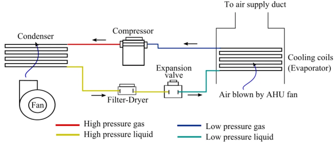
3.1.1 The vapor-compression based cooling unit
Figure 3.1 depicts the components of an air conditioning system for cooling based on a con-ventional vapor-compression cycle. A refrigerant circulates among the components of the unit changing its phase from liquid to gas and vice versa. The low pressure liquid refrigerant passes through the cooling coils and boils (due to a pressure drop as it leaves an expansion valve) causing the heat rejection from the coils surroundings and producing the cooling effect. Then, the low pressure refrigerant in gas phase is directed towards a mechanical compressor which increases its pressure and temperature. The hot, high pressure gas is conveyed to the con-denser where cold air blown by a fan is passing through the pipes. As the hot, high pressure gas circulates through the condenser coils, its heat is removed and transferred to outside air. Due to the heat removal, the gas refrigerant condenses. The high pressure liquid circulates towards the filter-dryer which absorbs any contaminants from the refrigerant and removes or holds the moisture to avoid its circulation through the system. Then, the expansion valve reduces the liquid pressure which is sent to the evaporator to begin the cycle again.
3.1.2 Economical and environmental aspects of the vapor-compression cool-ing unit
One of the major problems concerning vapor-compression based cooling units is the use of ozone-depleting refrigerants (HCFCs, hydrochlorofluorocarbons). The HCFC-22 (also called R-22) is the most common refrigerant used in air conditioning equipments. Important changes are being done in terms of regulation of emissions to the atmosphere, several amendments to the Montreal Protocol from 1987 include the phase out of the HCFCs in both developed and
Cooling-coils-(Evaporator) Toairsupplyduct - Air-blown-by-AHU-fan-Expansion valve- Compressor- Filter-Dryer- Fan-Condenser Low-pressure-gas- Low-pressure-liquid- High-pressure-liquid-
High-pressure-gas-Figure 3.1: The vapor-compression cooling unit.
developing countries. Consequently, the HCFCs must be replaced by ozone-friendly chloroflu-orocarbons (CFCs). The Environmental Protection Agency (EPA) of the United States has compiled a list of several alternatives to R-22 for household and light commercial air condi-tioning. One of these substitutes is R-410A which is touted as an environmentally friendly refrigerant that does not contribute to ozone depletion; however, it potentially contributes to global warming (Binggeli and Greichen,2011).
As the motor compressor operates at high speed, noise and vibrations are other inconveniences of this type of systems. Strong foundations are needed to maintain the system stable when it is operating. The compressor also requires maintenance as it is composed of several moving mechanical parts. Moreover, the wear or malfunctioning of the components can cause the leakage of the refrigerant which has to be recharged.
The main problem related to the vapor-compression based refrigeration units is the use of electricity: the compressor requires large quantities of electrical power for its operation. It is well known that electricity consumption around the world is continuously rising which leads to the rise of its price. This increase is largely due to more electrical appliances, the develop-ment of electrical heating in several developed countries and rural electrification programs in developing countries (OECD,2014). A study of the Organization for Economic Cooperation and Development (OECD) reveals that from 1971 to 2011, the share of electricity production from coal remained stable at 40-41%, the use of natural gas increased from 13% to 22% and the share of hydro-electricity decreased from 23% to 16%. Even if the use of renewable ener-gies such as solar, wind, geothermal, biofuels and waste for electricity production is increased, the share remains of limited importance: in 2011, they accounted for only around 4.5% of the world total electricity production (OECD,2014). As the electricity production comes mainly from fossil fuels, the CO2 emissions to the atmosphere are increasingly important.
Furthermore, in hot climate zones, air conditioning can significantly use large amounts of electrical power during higher-temperature periods of the day. This can then require utilities to supply expensive electricity, either from old and inefficient plants or from costly purchased grid power (Boehm,2012). For this reason, air conditioning loads are a major contributor to cause peak load on the power grid. Due to the heavy air conditioning demand, the cost for power generation is not only increased but also overall grid efficiency is reduced (Yoon et al., 2014).
3.1.3 The absorption cooling unit
It is not surprising that new environmental-friendly cooling technologies are growing up in order to reduce the global electricity demand. Despite the low COP, absorption cooling systems are an alternative to reduce this demand as they are driven by free-cost energy: instead of using electricity, the absorption cycle uses waste heat or solar energy to operate. Furthermore, solar-powered absorption cycles are particularly attractive because of the near coincidence of peak cooling loads with the available solar power (Li and Sumathy,2001). The use of ozone-friendly refrigerants as water or ammonia is one of the incentives to use this technology: they do not deplete the ozone layer and do not contribute to global warming.
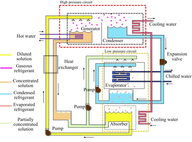
Figure 3.2: The absorption cooling unit.
Figure 3.2 depicts the schematic diagram of the absorption cooling unit. Four components can be easily identified: the generator and condenser in the high pressure circuit and the absorber and evaporator in the low pressure circuit. Instead of using a mechanical compressor, the absorption cooling unit uses a “thermo-chemical compressor” composed of the generator and the absorber to achieve the cooling effect. Consequently, the electricity consumption due to the vapor-compression is eliminated. Electricity in the absorption cycle is only used to
circulate a chemical solution through the elements of the unit using pumps. The main source of energy is thermal. Although the COP is lower than that of the vapor-compression cycle, if this energy is “free” (i.e. coming from solar or waste energy), then a large amount of energy is saved from the fact that, pumping a solution is easier and cheaper than compressing a vapor. Besides, the operation of absorption cooling units is smooth as moving parts are only present in the pumps. However, while maintenance is important for the proper operation of vapor-compression cooling systems, it is critical to the operation of absorption chillers. Two particular maintenance concerns are maintaining the proper vacuum within the shellside of the absorber and controlling corrosion within the chiller (Piper,1999).
Unlike the vapor-compression cycle, the absorption unit uses two fluids: the refrigerant and the absorbent. The most common solution is lithium bromide-water, where the lithium bro-mide compound is the absorbent and water is the refrigerant. It is worth noting that these components are nontoxic and environmentally friendly. Another common solution used in absorption cycles is the pair water-ammonia where ammonia is the refrigerant and water the absorbent. The main function of the absorbent is to carry the refrigerant from the absorber to the generator passing from a low to a high pressure environment. For this reason, the ab-sorbent should have two characteristics: strong affinity for the refrigerant and a boiling point higher than that of the refrigerant. The refrigerant and absorber are mixed in the various processes of the absorption cycle in different quantities which leads to: diluted, concentrated and partially concentrated solutions. In the diluted solution, the quantity of refrigerant is higher than that of the absorbent. In the concentrated solution, the quantity of absorbent is higher than that of the refrigerant. The partially concentrated solution is a mixture of diluted and concentrated solution.
Figure 3.3 represents the phases of the absorption cycle where four stages are carried out: Generator: The cycle starts in this component, where the refrigerant is separated from the absorbent using a heat source. A diluted solution (e.g. lithium bromide-water) in pumped out from the absorber to the generator. Afterwards, the chemical solution is heated using hot water or steam that circulates in tubes submerged in the solution. As the generator is located in the high pressure circuit and as the absorbent boiling point is higher than that of the refrigerant, this latter boils and it is separated from the solution. Consequently, the diluted solution becomes a concentrated solution. Then, the refrigerant circulates towards the condenser and the concentrated solution returns to the absorber.
Condenser: In this component, cooling water circulates through coils and the temperature of the cooling water is smaller than the temperature of the refrigerant vapor. As heat always flows from the warmer to the cooler environment, the heat from the refrigerant vapor is
transfered to the cooling water causing the condensation of the refrigerant on the surface of the coils. Normally, as the condenser temperature is hotter than the ambient temperature, the heat absorbed from the refrigerant vapor through the coils is transfered to the ambient air. The liquid refrigerant accumulates in the bottom of the condenser before passing to the evaporator.
Evaporator: The accumulated condensed refrigerant in the condenser circulates towards the evaporator through an expansion valve which reduces its pressure. Besides, a chilled water circuit circulates through coils in the evaporator. This water is responsible for rejecting the heat from the surroundings of the conditioned space. A pump located in the bottom of the evaporator pumps out the liquid refrigerant coming from the condenser spraying it over the coils surface. As the liquid refrigerant now has a lower pressure, its boiling point temperature is also lower. For this reason, the liquid refrigerant boils causing the cooling effect and removing heat from the chilled water. The refrigerant vapor is attracted to the absorber.
Chilled water Evaporator Absorber Condenser Generator Expansion valve Pump
High pressure circuit
Low pressure circuit
Cooling water Cooling water Heat exchanger Pump Pump Concentrated solution Diluted solution Gaseous refrigerant Condensed refrigerant Evaporated refrigerant Partially concentrated solution Hot water
Figure 3.3: The absorption cycle.
Absorber: A mixture of concentrated and diluted solution (the partially concentrated solution) is pumped out from the bottom of the absorber to the absorber sprays which leads to a better
heat transfer between chilled water and refrigerant/absorbent. At this stage, the refrigerant vapor is pulled into the partially concentrated solution which is the absorption effect. As the refrigerant vapor is absorbed, it changes from vapor to liquid state and it transfers heat to the cooling water that circulates through the coils. In addition, the mixture of concentrated and diluted solution is required to avoid the crystallization of the lithium-bromide compound. After the refrigerant is absorbed in the partially concentrated solution, this becomes again a diluted solution. Finally, the absorption cycle restarts pumping out the diluted solution to the generator.
A heat exchanger is used between the high and low pressure circuit. The concentrated solution coming from the generator towards the absorber transfers heat to the diluted solution coming from the absorber towards the generator. This energy exchange preheats the diluted solution before entering into the generator saving the heat required to separate the refrigerant from the solution. On the other hand, the heat exchanger precools the concentrated solution flowing to the absorber which leads to a lower cooling water flow rate required to reject the heat produced in the absorption process.
3.2
The solar absorption cooling installation
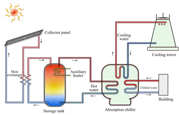
3.2.1 PresentationFigure 3.4 depicts one of the most common structures of solar absorption cooling systems (see e.g. Zhai et al.(2011); Yin et al.(2012); Lecuona et al. (2009)). The main components of the installation are: solar collector panel, heat exchanger, storage tank, absorption chiller, cooling tower and the conditioned building. This structure only provides cooling energy to the building. Other solar installations (see e.g. (ASHRAE, 2007)) are designed to distribute both heating and cooling to the building.
Flat-plate and evacuated-tube collector panels are used to concentrate solar energy which is transfered to a fluid (water or an antifreeze such as propylene glycol) that circulates in the tubes of the panel. The heat is then transfered to a water storage tank directly or using a heat exchanger as in Figure 3.4.
A stratified storage tank is used to provide the suitable hot water temperature value to the absorption chiller high pressure circuit. In a naturally stratified storage tank, buoyancy forces created by temperature dependent density differences maintain the separation between warm and cool volumes of liquid across a thin thermal transition region (thermocline). Flow into and out of a stratified tank occurs through diffusers at the top and bottom of the tank (Bahnfleth and Song,2005). Hot water coming from the heat exchanger enters at the top of the tank and circulates towards the chiller. Return chiller hot water enters at the bottom of the tank
Chilled water
Building Absorption chiller
Storage tank
Heat
exchanger Auxiliary heater
Cooling tower Cooling water Hot water Collector panel
Figure 3.4: Solar cooling system.
and circulates towards the heat exchanger. An auxiliary electric heater is located at the top of the storage tank in order to provide the required hot water to the absorption chiller when the solar radiation is low.
The process of heating the top layer of the stratified storage tank by using the water coming from the heat exchanger is referred as the loading state. At this stage, cold water is taken out of the very bottom layer of the tank, pumped through the heat exchanger and introduced back up, into the very top layer of the tank. A second operational mode is the tapping state where the heated water is taken from the top fluid layer, while an equal amount of cold water (coming from the chiller) is introduced at the bottom part of the tank. Thus, the vessel is always entirely filled with water. During the idle state where there is no loading and tapping, the hot water in the storage vessel gradually cools down due to losses through the wall. These operational modes reflect the discrete event dynamics of the storage tank where the transition from one discrete state to another is caused by a tapping event or by respective control actions, i.e. switching the electric heater on or off (Kreuzinger et al.,2008). According toEynard et al. (2012), the tank dynamics can also be described using two modes: energy storage and energy release modes.
As it can be seen in Figure 3.4, the absorption chiller has three water sources: hot water to separate the refrigerant from the solution in the generator, cooling water to reject heat from the condenser and absorber, and chilled water to distribute it to the conditioned space.
Commonly, a cooling tower is used to circulate the water for heat rejection. The cooling water coming from the chiller, which already has absorbed the heat from the absorption cycle, enters the cooling tower and it is distributed over the unit. By circulating air through the unit, a small portion of the cooling water is evaporated causing the heat rejection from the remaining water. The cooler water is collected in a basin located at the bottom of the tower and it is sent back to the chiller.
The chilled water that has absorbed the heat from the conditioned space is sent back to the chiller evaporator. Because of the pressure change in the evaporator, the circulating refrigerant absorbs the heat from the returned chilled water which causes a temperature drop. The cooler water is then recirculated to the building.
3.2.2 Impact of the sizing of components on the absorption cooling system performance and efficiency
Compared with the vapor-compression cycle based cooling system, absorption cooling systems have lower efficiency and high initial cost. In addition, to improve energy efficiency, they need a thermodynamic analysis as well as subsequent optimization of the parameters (Moreno et al., 2010). According to several studies reported in the literature, the efficiency improvement of solar cooling installations can be carried out by experimental tests analysis. For instance, Ali et al. (2008) reported the performance assessment of an integrated cooling plant with combined free cooling and solar powered single-effect lithium bromide-water absorption chiller based on experimental tests during five years of operation of the cooling installation which is fully automated, controlled and monitored. The plant has been additionally operated in connection to a building heating system in order to use excess solar heat for heating purposes and to utilize the available hot water of the building heating system as a supplementary source when the solar collector supply heat is not high enough to drive the chiller during cooling season.
Through these experimental tests, it is observed that one of the factors that affects the instal-lation efficiency is the sizing of the components (collector field size, collector angle orientation, storage tank volume, etc.). A method to select the optimal key parameters for a solar instal-lation (volume of the storage tank, slope and area of the collector panel) is investigated by Hang et al.(2013). The authors proposed a strategy that involves a central composite design (CCD) that is used to select the significant experimental data generated by energy system simulation and life cycle analysis. Besides, linear regression models are used to predict the functional relationship between system performance and the key system parameters using data sets. A multi-objective optimization model is solved based on the weighted Tchebycheff metric approach. The authors claimed that the proposed strategy simplified the design