Some Reflections
on
Model Predictive
Control
of
Transmission
Voltages
Mevludin Glavic, Member, IEEE, ThierryVan Cutsem,Fellow, IEEE
Some achievements on using MPC for system frequency Abstract- Thispaper deals with the application of algorithms control [18-20] and power plant control [21] problems have inspired by Model Predictive Control to solve voltage-related been reported. This paper, however, focuses on the control of power system control problems in both normal and emergency transmission system voltages.
operating conditions. In the first part of the paper, we identify We first discuss what webelieve are critical issues for the critical issuesfor apractical implementationofthismethodology,
andanalyze how far these requirements have been met so far. In applicaton ofMPG
techniques
to voltage control problems. the second part, we outline a voltage control scheme that For each issue, we briefly review some of the proposed hopefully addresses the above issues. The central idea of this approaches [6-17] and possibly identify some further research schemeis a static optimization to determine target control values, needs.followed by a dynamic optimization to produce a feasible Next, we outline a new
MPC
voltage control scheme for transition, both carried out in the closed-loop mode of Model normal and emergency system conditions that meets thePredictiveControl. nra
previously
n mrec ytmcn1osta et hidentified
requirements.
The controlstrategy
is Index Terms- Model predictive control, quasi steady-state made up of two parts: a static optimization to determine model,optimization, voltage control, secondary voltage control. movingtarget controls, followed byadynamicoptimizationto produce a feasible transition. Both are repeated at each time I. INTRODUCTION step according to the closed-loop structure of MPC. This ESIGNERS of power system controls have been always scheme offerssome similarities withtheso-calledcoordinatedI'concerned first and foremost with safety and reliability. secondary voltage control scheme, presently in operation in
Only those control techniques that are fully
understood,
part of the French transmission system.matured, and areguaranteed to work are used[1]. The paper is organized as follows. Section
1I
recalls the Model Predictive Control (MPC) techniques are both standardMPC
formulation. Section III addresses some of the mature (being considered a viable control strategy, they have critical issues forMPC
application to voltage problems, and been used for years in process industry [2,3]) and theoreticallybriefly
surveys the proposed approaches. Section IV outlines a understood (see [4,5] for a good account on the main newMPC
voltage control scheme while Section V offers theoretical results). It is thus somewhat surprising that up to some conclusions.now this control technique has not received more attention
from power system researchers and practitioners, although II. BRIEFREVIEWOFMODALPREDICTIVEGONTROL recent references show a growing interest for this approach Standard MPC (also referred to as moving horizon or
[6-21]. receding horizon control) is essentially a class of computer
Practical interest in using MPC is driven by the fact that controlalgorithmsto control the future behaviour of a system industrial processes need to be operated under tighter throughtheuseofanexplicitmodel of the latter [4,5]. At each
performance specifications and at the same time more and control step the MPC algorithm computes an open-loop more constraints (dictated by economical, environmental, and sequence of controls in order to optimize the future system
safety considerations) needto be satisfied [2,3]. This fact is, behaviour. The first control action inthe optimal sequence is more than ever, present in today's power systems. Precisely, appliedand the entire optimization is repeated at subsequent the ability of MPCto incorporatevarious constraints makes it control steps. Theprincipleof MPC is illustrated in Fig. 1. attractive in this respect. Obviously, one could also quote the It is convenient to formulate the MPC problem in the
growthincomputational power that allows performing faster- contextofadiscrete-time, nonlinear system described by [3]: than-real-time simulations, as well as the availability of
provenmodels and efficientoptimization algorithms. xk+=f
(X_
IU)v)
MeviudinGlavic([email protected]) is an invited professor of Yk =g(xk ) + Wk the University of Liege, Dept. of Electrical Engineering and Computer
Science, Sart Tilman B28, B-4000 Liege, Belgium. Thierry Van Cutsem where x is a vector of state variables, ilk a vector of ([email protected]) is with FNRS (Belgian Funds for Scientific k
Research) at the same department. controls, Yk avector of outputs or controlled variables, Vk
and
wk
arenoise vectors. definite. Other constraints than those shown in (4) may be considered as well. The weighting matrices and the bounds havebeen assumed constant for simplicity.setpoint An efficient implementation of MPC requires the following issues tobe addressedfirst[2-5]:
predictedoutput I
1.
system model: it should be both accurate andcomputationally tractable. To keep the problem tractable,
closed-loop one or several successive system linearizations areusually
output open-loop control sequence {ik} considered [2,3];
2.
sampling
time,prediction
and control horizons: theclosed-loop
UNcsampling
intervalbasically depends
on thesystem
control u U21
dynamics. The prediction horizon T should be chosen
p
long enough
so as to coverthesystem
settling
time. Thett+At I
t+TI
t+Tcontrol horizon T c prediction horizonc T control horizon T is
usually
a smaller than theprediction
horizon and represents the number of possible control moves. Short horizons are desirable from the Fig. 1. Principleof MPC
computational point
ofview,
but longhorizons
are Theproblem
is tocompute
a sequence of controlsrequired
forclosed-loop stability
and in order to achievethedesired
performance
inclosed-loop;
kU} c
3.
optimization
method:with
thequadratic objective function
current state xk to a desired steady state
xs
. The desired (2) and a linearizedsystem
model, the resulting optimization takes on the form of a highly structured steady state (xi, uS,y is either fixed or determined by a convex Quadratic Programming (QP) problem. Severalsteady-state optimization. In the latter case, it can be standard solution algorithms and codes are available for
computedeitheroncefor allor ateach time step. thisproblem [2-5].
The MPC algorithm consists in minimizing the objective
function: III. CRITICALISSUES INMPCAPPLICATION TO VOLTAGE
PROBLEMS
Np Nc-I
J
-Yk+j
-Ys
1Q
+I
j-us11R
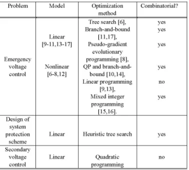
+ A. Overviewofproposed approaches
j=l j=0 (2) References [6-17,22,23] make up a representative (although
Nc-I certainly not exhaustive) sample of publications devoted to
Z
Uk+j
-
Uk+j1
S +ST
application ofMPC
to voltage-related problems.j=°
Expectedly,
theproposed approaches
do not allstrictly
subject
tothe constraints: adheretotheoriginal
MPCalgorithm,
but atleast all of them share twomajor ingredients
of MPC:prediction
andX
Xk+j
-=
f(Xk+j1,
Uk+j-)
j=I-,
N optimization. Among the"MPC-like"
schemes, some of them- +j^+1 J p (3) differfrom the basic MPC
algorithm
in thatthey
minimize aYk+j g(xk+j)
j I .-.,Np
given cost function by selecting the optimal sequence of y-S.Y±.7+ j1=,...,~N controlactions,
among available ones, and evaluate themy
s<Yk,j
< y + s= 1,
,Np
online, using the system model for performance prediction.U<
Uk+J
< j=1,...,
Nc
-1 This combinatorial search ispointed
out in Table1,
together
(4)
withsomeothercharacteristics.6<
Uk+j+l
-Uk+j
<6 j = ..*Nc
-1s>
0
B. Objectives and control meansIn normal operating conditions the objective is to keep
The first three terms in the objective function (2) aim at network voltages as close as possible to reference values. To
penalizing future deviations of outputs from the desiredsteady this purpose synchronous generators are the components it is state over the prediction horizon
T.
(N =Tv
/ At), future most natural to act on. It is also appropriate to control thedeviations of controls from the desired steady-state over the system in such a way that generators with a larger reactive control horizon Tc (Nc
Tc
/A\t),
and future rapid changes power capability participate more ("fair" sharing of reactive in cntrls,resectiely Th lat trm i (2 isuse to effort). Depending of the systemspecificities,
a variety of miimz th mantd of oupu cosranvoain.
Th other control means can be used [6-8,10-1 1,14-17]:.. synchronous condenser and
static
var compensatorvoltages,
weigtin marics Q R,S ad Tarechoen osiive
(capacitive
orinductive)
shuntcompensation,
voltage 626setpoints of more advanced FACTSdevices, voltage setpoints pilot nodevoltages and generator reactive powersateach time of Load TapChanging (LTC)transformers. step. It canbe said that this is theonly voltage control scheme
bearing some features of MPC and in realoperationtoday.
TABLE I In
emergency
conditions wherevoltages undergo
SAMPLEOFMPCAPPROACHES TO VOLTAGE-RELATED PROBLEMS g
unacceptable deviations from their reference values, or even Problem Model Optimization Combinatorial? become unstable, the objective is essentially the same; the method L maindifference is the higher speed and magnitude of actions Branch-and-bound yes needed. It is well-known that higher source voltages yield
Linear [11,17], higher load power margins and a quickincrease of generator [9-11,13-17] Pseudo-gradient yes voltages may contribute to stabilizing a system, or at least to
evolutionary
Emergencyvprogramiong
[8],reducing
the size of moredrastic
countermeasures.voltage Nonlinear QP andbranch-and- yes Furthermore, control means may include load shedding in the control [6-8,12] bound[10,14], last resort. Where system integrity is
endangered,
corrective Linearprogramming no actions maybe taken atthe
expense of some sub-optimality,[9,13], the priority being to save the largest possible part of the
Mixedinteger yes system.
programming
[15,16]. The main expected advantage of MPC in emergency
Design of operating conditions is again the coordinated control of the
system various control means. This is even more crucial since
protection Linear Heuristictreesearch yes operators maybeworkingunder stressand the system is close
scheme
Secondary to or outside its normal limits
making
the control task evenvoltage Linear Quadratic no more delicate. To our best knowledge, the present SVC
control programming schemes donothave a
particular
emergencymode. We believethat emergencyvoltage controlis the areawhere an
efficient
The mainexpected advantage of MPC in normal operating MPCalgorithm couldprove
mostuseful.
conditions is the coordinated control of the various control Load shedding has been considered as a control means by
means. Such a scheme would relieve the control center several authors either together with other controls [6-17] or operators from the heavy and possibly delicate task ofaln [91]Foistceann-srpveodcnrl
succesivelydjustignumeous
cotrols.alone
[9,13].
Forinstance,
anon-disruptive
load controlAsucesv
adjusting
conuemerou
conterols.
variantsoft scheme has beenconsidered
in
[9,13],as ahierarchical
controlAstafard quasdMPis
njctiverfuned,o
o de2ent
vantuseo
t structurewhere an MPCcontrolleracts atthe upper level andstandard quadratic objective function (2) have been used In coordinates lower (substation) level controllers.
several cases, the objective includes all but the second term In theory, an MPC scheme would benefit from a wide view
[6-8,12]. As a variant of the fourth term, a penalty can be of
theosys
atingstae,
aould
benat
the a of aintroduced whenever a constraint violation or a singularity-
wide
system,
ang for
i e t ter ainduced bifurcation is predicted to occurwithin a prediction
the am
eand
loction
ofload sheding
toterbance
horizon. In [8] apenaltytermhas been also addedto account ofconcern.
Howeth
edof load stough
ancfor onsrain vilatons nd nstailiy. he ojecive of concern.
However,
theshedding
of loadsthrough
anMPC for constraint violations and instability. The objective scheme may be questioned by practitioners. Indeed, even in functions of[14-17] include the first threeterms of(2). Somethece
of l estititnmay
be
ed topublications penalize the amount of control at each sampling
she
lad wtns
nterm
the
stub
ance rence
[6 time butno publicationincludes the second term of(2)whichand
itishn
clar
whter
anMCscheme
ouldebe
fastpenalizes future deviations of controls from the desired
enough. Moreover
insuh
asys
emecton
seme,
steady-state.
~~~~~~~enough.
Moreover,
in such asystem
protection
scheme,
steady-state. preference is given to simplicity for reliability reasons. The
To some extent, the above voltage control task is performed many components that enter an MPC-driven load shedding
automatically bySecondary Voltage Control(SVC). The first
schme
onceas
th.eroab
failurei.e
ldeshed
generation of SVC, inoperation in France and
Italy,
relies onproteincreli
ability)o
undere
loashe
reactive power controlloops in powerplants andacentralizedcontrollers
make up a much simpleralternative.
PI controller to regulate the voltage at apilot node (whose voltage is representative of the other bus voltages in the area
of concern), while sharing the effort over the participating C. System modelling
generators according to predefined participation factors [24, The response time of an MPC-based
voltage
control25]. ranging from - say - 10 to 60
seconds, long-term
dynamics
Interestingly, the second generation of SVC [22], in are of concern. In this context, it is appropriate to resort to the operation in some parts ofthe Frenchsystem, can be seen as a Quasi-Steady State (QSS) approximation of the long-term special implementation of the MPC concept, in so far as it dynamics [27]. The essence of this method is time-scale relies on the multi-step optimization of a quadratic voltage- decomposition, faster phenomena being represented by their reactive power objective, embedding new measurements of equilibrium conditions instead oftheir full dynamics.
Most of the listed publications resort more or less implicitly 627
to this technique, which greatly reduces the complexity of the restrict the use of the faster-than-real-time QSS simulation to resulting model and hence provides the computational the early detection of a situation evolving to emergency efficiency required to meet the constraints of an on-line conditions. This may be used to trigger an emergency mode in application. Moreover, the amount of additional data required the algorithms.
by the QSS model is moderate, so that data collection,
validation and maintenance are not a big issue. D. Trajectoryprediction
The
Q
SSmodel takesonthe form: The prediction of the future system behaviour is an important part of any MPC algorithm. However, the nonlinearo =
g(x1,
x2, y,
z) (5) model (5-8) cannot be easily used to this purpose. As0=
fl
(x,x2,y,z) (6) mentionedpreviously,
it isrequired
to resort to some sort ofmodel simplification. Among the main techniques used to this x2 = f2
(xl, x2:
y'
z) (7) purpose let us quote [6]:z(t+)
h(x1,x2,yz(t))
(8) 1. Euler stateprediction [6-8,12],
which has been usedtogether with an approximation of the output trajectories where
Eq.
(5)
stands for the networkequations
(y being
theby
onestraight
line betweentheir values atthebeginning
vtob vledynamics and the end of the
prediction
interval[6-8].
Euler statevector ofbus voltages), Eq. (6) for the short-term dynamics predictionapplies to Eq. (7) ofthe QSS model;
replaced by equilibrium conditions
(xi
being the corres- 2.off-equilibrium
dynamic linearization [6,14], whichponding algebraic variables), Eq. (7) for the continuous long- consists of a classical linearization of Eqs. (5-7) term dynamics (corresponding state vector x ) and Eq. (8)2 performedgenerally not anat theequilibrium).current
operating point (which
This linearization can beis captures discrete events stemming from controllers (e.g. performed numerically [6] orsymbolically [14];LTCs), protections (e.g. OverExcitation Limiters (OELs)) and 3. trajectory sensitivities [9,11,12,17] which provide a
possibly system protection schemes (e.g. load shedding if systematic way to compute sensitivities of the trajectory taken care ofbylocal controllers), causing the variables z to of x2 (Eq. (7)) with respect to changes in parameters,
undergo step changes at some times tk . Note that when the initialconditions, and structural changes. The approach is long-term dynamics are driven by LTCs and OELs only, the based on linearizing the system model arounda nominal QSS systemtrajectory amounts to a succession of short-term trajectory [30]rather thananequilibrium point. Therefore
equilibria, each being the solution of Eqs. (5, 6) and the it is possible to quantify the variation of a trajectory changefrom oneequilibriumtothe next being dictated by (8). resulting from a (small) change in parameters, and/or The interested reader may refer to [27, 28] for a more detailed initialconditions,and /or structuralchanges.
descriptionof the abovemodel, as well as some extensions of We note incidentally that very few references take into
the QSStechnique. accountthe discrete nature of the transitions captured by Eq.
QSS simulation is very fast andcompatible with the on-line (8), which are the only long-term dynamics for a system
requirements. For instance, it takes less than 2 seconds to driven
by
LTCs and OELs.simulate the 15-minute response of a 1000-bus system to a Moreimportantly, it seems that most approaches rely on the large disturbance [28]. The technique thus offers the knowledge of the whole system state in order to predict its
possibility to evaluate the system response much faster than future evolution. This requires including the EMS state real-time. Following a large disturbance, assuming that the estimator in the MPC loop, which is not desirable as far as the
change
intopology
can beidentified,
it isquite
feasible toconvergence,
unobservability
and bad dataproblems
it mayanticipate the system behaviour from a QSSsimulation of the
experience, especially
in emergencyoperating
conditions,
disturbance,
initialized from thepre-disturbance
conditions. wouldimpair
thereliability
of theMPC
scheme. On thecontrary an MPC scheme that relies on dedicated
The same fasttechniquecould also be used todetermine the mr
controls to apply to regulate network voltages. However,
remaining
of.th
stesat
vector
pasawighl
models are always
approximations,
especiallythose involving desirablefeature, even if the price to pay is a decrease in the uncertain load behaviour; therefore, it may not be model accuracy.acceptable, especially in emergency conditions to apply
controls determined from the sole QSS model. The motivation E Combinatorial
handling of
discrete controls forusing
MPC isprecisely
to compensate for those modelinaccuracies, by implementing the controls in a closed-loop The fact that some controls (e.g. LTCs or shunt m"l""an ilv t rerom teym
compensation)
are discreteby
nature has led some authors to BesidesMPG
itself, it remains of interest to set up a adopt at least a hybrid, if not a fully discrete formulationtehiu*
ocretteQSmdlfo h iceace (considering that some continuous controls can be reasonably observed between the measured and the simulated system discretized). Expectedly, the large number of controls evolutions. This appears, however, to be a very challenging available in a real-life power system, together with their problem. For thetime being, it
appears more reasonable to cmiaina ucsietm tp ed ohglcombinatorial problems. This implies in practice that a huge 628
number of system responses would have to be evaluated scheme and concentrate on generator
voltages
and shunt online. For instance, for a simple 6-bus system [6-8] with 8compensation
as controls. LTCsetpoints
could be available controls as many as 2,000 online evaluations of the includedaswell butarenotconsidered here forsimplicity
system evolution were envisaged in order to determine the * avoid combinatorial optimization forefficiency
reasons;control sequence! instead,treatdiscrete controls inacontinuous way
The discrete nature of the problem also motivated some * use a relatively simple sensitivity model to anticipate the authors to use a hybrid approach based on mixed
logical
future system behaviour, counting on the closed-loopdynamic framework [11,15,16].
Although
elegant,
this nature ofMPCtocompensate for those simplifications approachseems tobeeven morecomputationally
demanding.
* derive the corresponding sensitivities through formulaeMethods that cut down the combinatorial
explosion
are exploiting the sparsity of standard power system models thus essential. In this context, Refs. [6-8,12]proposed
to . avoid relying on the EMS stateestimator inside theMPC
resort to heuristic or meta-heuristic optimization methods control loop
while in [11,17] the problem was tackled
using
the branch- . rely instead on dedicated measurements relative to and-bound method. The same optimization method wasused selected busvoltages and to the above listed controls in [14] to solve the discrete control part of theproblem,
. allow faster responses if emergency conditions aretogetherwithQP for continuous controls. In
[15,
16]
amixed detected.integer programming method has been used with the
help
of The proposed scheme is to some extent inspired of the CPLEX softwareenvironment,previously
mentioned
Frenchcoordinated
secondary
voltage
Some figures about the
complexity
ofreported
tests are control [22].However, it differs from the latter by its expected given in Table 11. Itreveals thatonlysmall-size systems have ability to respond more quickly in more severe situations and been used so far to demonstrate effectiveness of MPC by the way the future evolution is optimized. In thisrespect,
techniques. The average time taken
by
theoptimization
the scheme of [22] does not involve multiple prediction steps method in [8] is 61.1 s (using simple Euler statepredictor).
into theoptimization
but rather corrects a fraction of theThe authorshopethat thiscomputingtimecanbe
improved
by
voltage deviations at each time step.better software implementation [8]. However, the
viability
of The proposed scheme has also some similarities with the the method has still to be checked on real-life systems. The flexible coordinated secondary voltage control introduced in averagecomputingtimes reportedin [16] for theoptimization
[23],
from which it differs,however, in both the static and the are inthe order of 1.8 sfor4prediction
steps and 160 s for7 dynamic optimization sub-problems (an optimal unbiasedprediction steps. Again, these times relate to a very
small,
4- Kalman predictor has been used in [23]) as well asbustestsystem[15,16].
implementation
andmodeling
details.Some combinatorial
approaches
seem motivatedby
the search ofaglobally optimalcontrol sequence. In both normaland emergency conditions, this questfor
optimality
seems A Required information and modelsomewhat utopian insofar as the
objective
considered here is We re-use the idea, implemented in Secondary voltage more technical than economical(at
least aslong
the market control, of monitoring the transmission voltages at pilotdoesnotput financialpenalties on
voltage
deviations!).
nodes. The main motivation is to limit the number of busvoltage measurements that have to be telemetered and
TABLEII processed centrally. The voltage at a pilot node is assumed to
COMPLEXITY FIGURES OF REPORTED TESTS be
representative
of thevoltages
in awhole areasurrounding
Predictionhorizon/
Problem Testsystem sampling this bus. Letp be the number of
pilot
nodes andvp
the4-bus[10,16] 30-150s/30s[10]
6-bus [6,8] 120s/30s,70s/10s[16] vectorof pilotnode voltages.
Emergency voltage 9-bus[14] 120s/30s[6] Let g be the number of generators whose voltages are control 10-bus
[9,13]
60s/5s
[11,17]
controlled, v the corresponding vector of terminal voltages12-bus [15] 60s/30s [8] g
32-bus
[7,11,17]
50s/50s[9,13]
and q the one ofreactivepowerproductions.39-bus[8] 90s/30s[14]
Designofsystem Let c be the number of buses where shunt compensation
protection scheme 32-bus 120s/30s[7]
againstvoltage can be
adjusted
andbc
thecorresponding
vector of shuntcollapse
admittances.
IV. OUTLINING A REALISTICMPGCONTROL SCHEME We define the followingvectorsof setpointvalues: ref for
We outline hereafter a voltage control scheme inspired of pilot node voltages,
qge
for generator reactive powers and theMPG
methodology and satisfying the following erequirements, stemming from the considerations of Section
bre
for shunt compensation.v'ref
can be determined by anIII: Optimal Power Flow aimed at minimizing the system power
* leave load shedding to a distinct system protection 629
losses [22]. The choice of
qref
and bref will be discussed in Av =S Av +S Abthe sequel. At step k, we assume that pilot node voltage p pg g (12)
measurements and reactive power generation measurements
Aqg
=SggAvg
+SgcAbc
are made available to the MPC algorithm in respectivelyv~,
(k)
andqg
(k).
We also assume that the status of shunt in whichA denotes small variations and the various matricesp 9 are assembled row by row, each row being obtained from
devices is known, which is translated into a vector of (11)
"measured" shunt admittancesbc(k). An
important
aspect is theupdate
of the above matrices. We propose to evaluate them when the system is in (almost) steady state and keep them constant as long as operatingB.
Sensitivity-based
trajectory
prediction
conditions do not change significantly. Note that Eq. (1)As alreadymentioned, a linear approximation of the future
requires knowing
the wholesystem stateand hencerelying
on system behaviour is desirable for incorporation inthe overall the networkvoltages
provided by
theEMSstateestimator. MPC optimization. We propose to derive the corresponding When a disturbance occurs, such as a line or a generatorsensitivities from the system conditions at equilibrium. In outage, the
sensitivity
matrices must beupdated.
Now, it isother words, the sensitivities will indicate how much the
precisely
over thepost-disturbance
time interval thatvoltage
steady-state values of pilot node voltages and generator control is needed. In order not to
rely
on the state estimatorreactive powers change with generator voltages and shunt output in that
period
oftime,
it isproposed
to solve theadmittances.
equilibrium equations
(9)
for the newtopology
(this
isWe thus consider the QSS model (5-8) at a
long-term
equivalent
to the standardcontingency
evaluation)
andequilibrium: recomputethe
sensitivity
matrices atthenewoperating point.
When the real system settles down at a new steady state,the 0=
g(xl,
x2,y,z)
matricescanbe refreshedusing the network voltagesprovided0=
fl
(xl,
x2,
y,z)
by
thestateestimator.(9) The following two optimizations are carried out at each
0=
f2(xI,x2,y,z)
timestep k.O=
he(XI,x2,Y,z)
C. Firststep. determining target controls
where the last
equation
stands for theequilibrium
conditions The objective is to determine what would be the bestof the discrete devices. For anon-limited LTC, for
instance,
controlsAv*
andAb*
toapply
in a(fictitious) single
step,thisequation takes onthe
simple
form: gbased onthe available sensitivity information andtaking into
V = V° accountanumber of constraints.
cont cont To this purpose, the following objective function is
where VVcont is thevoltage controlled by theLTCand
Vo
cont the minimized:correspondingsetpoint (midpoint ofLTCdeadband). J, ve -
vp
(k)-Spg
Avg -Spcbc
12
+The aboveequationscanbe rewrittenin compact formas:
qre
-qg
(k)-
S,Avg-SgcAbc
112
+
(13)
f(x, u)
=o(10)
b ef-bCb
112
C
CC
where u is the controlvector ofgenerator
voltages
and shuntadmittances and x anaugmented (algebraic) state vector.Let with respect to
Avg
andAbc
,taking
into account theq be either a pilot node voltage or a generator reactive followingconstraints:
power. The sensitivity of q withrespect to u is
given by
* generatorvoltages in acceptable operating ranges:[31]:
vmin <v
g(k)+Avg
<vmax
(14)S77U
=fu' (fx'
)_
vV
(11generator reactive powers compatible with
capability
where fu (resp. fx is the Jacobian matrix of f with respect curves:
toiu
(resp. x) andV,x
is the gradientofq with respect toinqg(k)+SggA\vg+SA\b
.<qrna
(15) x. The well-known formula (11) has been used in manyvoltagestability studies [27, 31]. * shunt compensation within available limits: There fromone easily derives the linear model:
bminb(k)+±\b
bm (16) under reactive limits) and compensate for modeling errorsthrough the closed-loop structure.
Clearly, the objective of the first term in (13) is to bring To this purpose, a second optimization problem is solved pilot node voltages to their setpoint values. Assume that none whose objective is to minimize the future deviations of
of the constraints is active and the numberpofpilot nodes is controls with respect to target values, i.e.
lower than the number gof controlling generators (as is the Nc 2 Nc
case in
practice
forsecondary voltage control). Then,
J2 = Vg(k>Vg(k+j)
+9
b(k)-bC(k+j)
(15considering only thefirsttermof the objective would yieldan j4 j4
undetermined problem. The remaining g-p degrees of )
freedomcanbe usedtoadjust thegeneratorreactivepowersin
subject
tothefollowing
constraints: some optimalway. This is thepurpose of the second term in t .(13).
Withqgef
=0,
the latter will tend tomaximizing
thefor
0=
O,
...,,Nc
-1: reactivepower reservesavailableon generators.Inthe objective (13), the weighting matrices P, G and C vg(k
+j+1)
vg(k+j)
+Avg
(k+j)
are diagonal with positive entries. The weights in P should g (16)
be significantly larger than those in G so that the primary
bc(k+j+1)bc(k+j)+Ab (k+j)
task of controlling the network voltages is achieved. The
diagonal entries of G must also reflect the reactive power * rate of
change
of controls withinspecified
range:capabilities
of thecorresponding
generators
(the
greater
the forj
=0,...,
NC
-1:capability, the lower the weight).
If shunt compensation is available for control, an
-Avmax
<Av
(k+j)<
vmaxoptimization based only onthe first two terms in(13) might g - g (17)
lead to over-compensating the system, since this will relieve
-Abmnax
<Abc
(k
+j)
<Abmaxgenerators and hence decrease the second term. The purpose
of the thirdtermis precisely toprevent excessive amounts of * generator voltages in acceptable operating ranges:
shuntcompensationtobe switchedon,by keeping
bc
closeto forj 1,.,
Nc:
bref
,which would betypicallyset to zero. Sometuning of Cmay
berequired
to reach thisgoal.
Alternatively, voltage
vtm'11
. (k+I)+Avg(k+I).v9ax (18) limits could be assigned to the buses where shuntcompensation is available (which requires monitoring those * generators reactive powers compatible with capability
bus voltages). Tests are neededto determine which approach curves:
is themostsatisfactory. for
j
=1,,Nc:
The above optimization problem can be solved using a
standard
QP algorithm.
qmin .qg(k+j)
+SggAVg (k +j)
+The solution so obtained
defines
thefollowing moving
g g(19)
target
values of the controls:SgcAbc(k
+j)
<qmax
v>(k) vg(k)
+Av(
Other constraints could be included as well. Out of thisb*(k)
bc(k)+
Ab*
controlsequence,
the firststep,
i.e.[vAg(k)
Abc(k)]
is
applied and all the procedure repeatedatthenexttimestep. Notethat thesetargetvaluesare
updated
ateach timestep k. The boundsAVrnax
on generator voltage changes are goingto be important parameters since they will dictate the rate at
which
voltageswill
be corrected. One mayenvisage using
Inthe spirit ofMPC, the objective of the second step isto wider bounds (i.e. steeper changes) in emergency conditions,determine a sequence of near-future control changes the latter being identified as indicated at the end of Section
corrections {AVg (k+
j),
Ab (k+j)}
( i
=0,...,
N_
-1)
that III.C.ter We do not envisage shunt compensation as a discrete
will~~~ ~
brn_sqikya
osil h otosfovariable.
Instead, we rely on the usualsimplification
which
current value[Vg
(k)bc
(k)]
tothle
moving consists inrounding
off the continuous value to the nearest(k _ discrete value. We expect that the approximation will be also
target
Lvg
htb(k)].
The motivationfor
usingMPG
is to compensated by the closed-loop nature ofMPG.
produce a feasible transition (e.g. avoid switching generatorsV. CONCLUSION [13] I. A. Hiskens, B. Gong, "Voltage stability enhancement via model predictive control of load", In Proc. of BulkPower System Dynamics
In this paper, several approaches to model predictive and Control VI, CortinadAmpezzo, Italy, Aug. 2004.
control of transmission voltages have been surveyed in the [14] S. Leirens, P. Bastard, J. L. Coullon, "A hybrid approach forvoltage
perspective of a practical application. The survey reveals stabilityof power
systems",
In Proc.of15th
PowerSystem ComputationConference,Liege, Belgium, Paper fp291, August,2005.
growing interest, at least inthe research community, in using [15] A. G. Beccuti, T. Geyer, M.
Morari,
"A hybrid system approach to MPC techniques. This is to be expected considering the power system voltage control", In Proc. of44th IEEE Conference on maturity and success reported in other industrial applications Decision and Control, Sevilla, Spain, December, 2005. [Online]Available:http://control.ee.ethz.ch
as well the availability of technologies supporting its [16] T. Geyer, M. Larsson, M.
Morari,
"Hybrid emergency voltage control inimplementation in power systemcontrolcentres. powersystems",In Proc.ofEuropeanControlConference, Cambridge, MPC has indeed some potentialities but some practical 2003.
[17] M. Zima, G. Andersson, "Model predictive control of electric power
Issues have to be considered, and more work iS needed
in
systems underemergency conditions", In Real-time stability in power order to ascertain that it is viable and eventually convince systems: Techniques for early detection of the risk of blackouts,practitionersto startusing them. Springer, 2006.
In the light of those practical issues, a possible MPC [18] N.compliant decentralized load frequency control
Atic,
D. Rerkpreedapong, A. Hasanovic, A. Feliachi "design using modelNERC scheme has been outlined which applies to both normal and predictive control", In Proc. ofIEEE PES General Meeting, vol. 2, emergency conditions. The scheme includes a static Toronto,2003.optimization to compute target control values and a dynamic [19] N. Atic, A. Feliachi, D. Rerkpreedapong, "CPS1 and CPS2 compliant
optimization topoduca eae.
Bwedge-shaped
model predictive load frequency control", In Proc. ofoptimization to produce a feasible
transition.
Both are IEEE PES General Meeting, vol. 1,pp. 856-860, Denver, 2004. repeated at each time step in order to exploit the closed-loop [20] A.N.Venkat,I.A.Hiskens,J.B.Rawlingsand S.J.Wright, "Distributed nature ofMPC andthereby compensate formodelling errors MPC strategies for automatic generation control", In Proceedings of theIFAC Symposium on Power Plants and Power Systems Control,
and other sources ofuncertainty. Kananaskis, Canada, June 2006.
Ofcourse,the effective advantagesof thisproposedscheme [21] E. Gallestey, A. Stothert, M. Antoine, S. Morton, "Model predictive remaintobe carefully assessed through realistictests. control and optimizationof power plant load while consideringlifetime
consumption", IEEETrans. on PowerSystems,vol. 17,no. 1,pp. 186-191,Feb.2002.
ACKNOWLEDGMENT [22] H. Vu, P. Pruvot, C. Launay, Y.Harmand,"Animproved voltage control
The authors gratefully acknowledge the support
from
oflarge-scale powersystems",IEEETrans.onPowerSystems,vol. 11,pp. 1295-1303, Aug. 1996.
FNRS(Belgian National Funds for Scientific Research). [23] B. Marinescu, H. Bourles, "Robust predictive control for the flexible coordinated secondary voltage control oflarge-scale power systems",
VI. REFERENCES IEEE Trans. on Power Systems, vol. 14, no. 4, pp. 1262-1268, 1997.
[24] J. P.Paul,J. Y.Leost, J. M. Tesseron,"Survey of thesecondary voltage
[1] P.Kundur,"Power systemstability andcontrol",McGraw-Hill, 1994. control in France: present realizations and investigations", IEEE Trans. [2] S. J. Qin,T.A.Badgwell, "Anoverview of industrial modelpredictive on Power Systems, vol. 2, no. 2, May1987.
control technology", ChemicalProcess Control, vol. 93, no. 316, pp. [25] V. Arcidiacono, S. Corsi, "New developments in the application of 232-256, 1997. ENEL transmission system and reactive power automatic control",
[3] S. J.Qin,T.A.Badgwell, "Anoverview of nonlinear modelpredictive CIGRE 1990.
control applications", In Nonlinear Model Predictive Control, [26] T. Van Cutsem, C. Moors, D. Lefebvre, "Design of load shedding
BirkhauserVerlag,pp.369-392,2000. schemes against voltage instabilityusing combinatorial optimization",
[4] D. Q. Mayne, J. B. Rawlings, C. V. Rao, P. 0. M. Scokaert, Proc. of the IEEE PES WinterMeeting, New York, Jan 2002, IEEERef. "Constrained model predictive control: Stability and optimality", 0-7803-7322-7/02
Automatica, vol.36,pp.789-814,2000. [27] T. Van Cutsem, C. Vournas, "Voltage stability of electric power [5] R. Findeisen, F. Allgower, "An introduction to nonlinear model systems",Kluwer AcademicPublisher, Dordrecht, 1998.
predictive control", In Proc. 2002 Benelux Meeting on Systems and [28] T. Van Cutsem, M.-E. Grenier, D.Lefebvre, "Combining detailed and
Control. quasi steady-state time simulations for large-disturbance analysis",
[6] M. Larsson, D. J. Hill, G. Olsson, "Emergency voltage controlusing International Journal ofElectricPowerand Energy Systems, to appear,
search andpredictivecontrol",International JournalofElectricPower 2006.
andEnergySystems, vol. 24,pp.121-130,Jan.2002. [29] D. S. Popovic, V. A. Levi, Z. A.Gorecan, "Co-ordination of emergency
[7] M. Larsson, D. Karlsson, "Coordinated system protection scheme secondary-voltage control and load shedding to prevent voltage
against voltagecollapse using heuristic search andpredictive control", instability",IEEProceedings-Generation, Transmission, Distribution, IEEETrans. PowerSystems, vol. 18,pp.1001-1006, Aug.2003. vol. 144, no. 3, pp. 293-300, May1997.
[8] J. Y. Wen, Q. H. Wu, D. R. Turner, C. J. Cheng, J. Fitch, "Optimal [30] I. A. Hiskens, M. A. pai, "Trajectory sensitivity analysis of hybrid
coordinatedvoltage control forpower systemvoltage stability",IEEE systems", IEEE Trans. on Circuitsand Systems-Part I, vol. 47, no. 2, pp. Trans. PowerSystems, vol. 19,pp.1115-1122, May2004. 204-220, Feb. 2000.
[9] I. A. Hiskens, B. Gong, "Voltage stability enhancement via model [31] F. Capitanescu, T. Van Cutsem,"Unified sensitivity analysis of unstable
predictive control ofload", IntelligentAutomationandSoft Computing, or low voltages caused by loadincreases or contingencies", IEEE Trans.
vol. 12,no.1,pp.117-124,2006. on Power Systems, vol. 20, pp.321-329, 2005.
[10] S.A.Attia,M.Alamir,C.Canudas deWit, "Voltage collapse avoidance
inpower systems: areceding horizon approach", IntelligentAutomation and SoftComputing, vol. 12, p. 12, 2006.
[11] M. Zima, G. Andersson, "Stability assessment and emergency control method using trajectory sensitivities", In Proc. of Bologna PowerTech, 2003.
[12] D. J. Hill, Y. Guo, M. Larsson, Y. Wang, "Global hybrid control of power systems", In Proc. of Bulk Power System Dynamics andControl
V,Onomichi,Japan, Aug. 2001.