Publisher’s version / Version de l'éditeur:
Proceedings of Advances in Hydroelectric Turbine Manufacturing and Repair, 2013
READ THESE TERMS AND CONDITIONS CAREFULLY BEFORE USING THIS WEBSITE. https://nrc-publications.canada.ca/eng/copyright
Vous avez des questions? Nous pouvons vous aider. Pour communiquer directement avec un auteur, consultez la première page de la revue dans laquelle son article a été publié afin de trouver ses coordonnées. Si vous n’arrivez pas à les repérer, communiquez avec nous à [email protected].
Questions? Contact the NRC Publications Archive team at
[email protected]. If you wish to email the authors directly, please see the first page of the publication for their contact information.
NRC Publications Archive
Archives des publications du CNRC
This publication could be one of several versions: author’s original, accepted manuscript or the publisher’s version. / La version de cette publication peut être l’une des suivantes : la version prépublication de l’auteur, la version acceptée du manuscrit ou la version de l’éditeur.
Access and use of this website and the material on it are subject to the Terms and Conditions set forth at Development of an inverse method for material characterization
Saboori, M.; Champliaud, H.; Gholipour, J.; Gakwaya, A.; Savoie, J.; Wanjara, P.
https://publications-cnrc.canada.ca/fra/droits
L’accès à ce site Web et l’utilisation de son contenu sont assujettis aux conditions présentées dans le site LISEZ CES CONDITIONS ATTENTIVEMENT AVANT D’UTILISER CE SITE WEB.
NRC Publications Record / Notice d'Archives des publications de CNRC:
https://nrc-publications.canada.ca/eng/view/object/?id=07e725dc-7c5e-4299-b85a-9cc38574a708 https://publications-cnrc.canada.ca/fra/voir/objet/?id=07e725dc-7c5e-4299-b85a-9cc38574a708
DEVELOPMENT OF AN INVERSE METHOD FOR MATERIAL
CHARACTERIZATION
M. Saboori12*, H. Champliaud1, J. Gholipour2, A. Gakwaya3, J. Savoie4 and P. Wanjara2 1École de technologie supérieure, Montréal, Canada, [email protected]
2National Research Council of Canada, Aerospace, Montréal, Canada, [email protected]
3Laval University, Québec city, Canada, [email protected] 4Pratt & Whitney Canada, Special Process Development Group, Longueuil, Canada,
*Corresponding author: [email protected]
Keywords: Inverse Method, Finite-element simulation, Material properties
Abstract
Conventional engineering analysis involves the determination of material properties under uniaxial loading conditions. The true stress-true strain curves generated through this way have been used in finite element modeling (FEM) of various forming processes. However, this method is only valid up to the onset of necking; after this point the stress state is not uniaxial and the errors between FEM results and experimental data are significant. In this paper a new work hardening equation for predicting material behavior after the instability was used for stainless steel 321 (SS 321) and Inconel 718 (IN 718). A finite element model based on an inverse method was devised with the aim of determining the properties of isotropic materials after instability. To facilitate the process of material characterization, an algorithm was developed using LS-DYNA and Matlab software. Verification of this methodology was carried out by comparing the experimental load-displacement data (obtained by tensile testing) with the simulation results.
Introduction
For efficient and cost effective evaluation of most manufacturing and metal forming processes, implicit or explicit FEM can help in the development and optimization phases. The precision of the simulation results depends on the accuracy of the input data (material properties, constitutive equations, friction condition, etc.) utilized in the FE model. However, in the case of large plastic deformations, characterization of the true stress-true strain behavior is only accurate prior to necking. After necking, the true stress-true strain behavior is difficult to evaluate since the stress state evolves from uniaxial to triaxial. Specifically, at the start of the necking phenomenon, radial and hoop stresses arise; the uniaxial state and uniform deformation across the gauge length thus change to a triaxial state and localized deformation in the neck region. The material behavior up to the onset of necking has been determined by different work hardening models, but a good knowledge of the plastic behavior after necking is necessary for performing an accurate simulation, specifically in the case of failure prediction [1].
The standard uniaxial tensile test is a common way to determine the stress–strain behavior of a material. The true stress-true strain curve calculated in this way is accurate up to the maximum load. The work hardening behavior beyond this point is usually estimated by extrapolating the stress-strain curve from the localization point by considering the tangency
condition between the experimental data and the extrapolated curve. However, such a procedure may be ineffective in simulating and accurately analyzing the behavior of the material after necking, since multiple extrapolated curves can be generated using the tangency condition only.
Bridgman [2] developed a theoretical model for round geometry specimens based on instant profile and instability phenomenon, but his approach is not applicable for specimens with a rectangular geometry. More recently, an analytical procedure was introduced by Zhang et al. [3] for tensile testing of specimens with a rectangular geometry. However, the validation of this method is limited to specimens with a cross-sectional aspect ratio (width/thickness) of up to eight. In contrast, Coppieters [4] used an inverse technique without developing any hardening model to study the flow behavior of a deep drawing mild steel after necking. Koç, Ling and Zhang [5-7] combined FEM with experimental measurements to determine the material behavior after the onset of necking.
In this paper, the flow behavior of IN 718 and SS 321 was studied on the basis of uniaxial tensile test data that were analyzed by an inverse method that allowed the determination of the true stress-true strain behavior of the material after necking. Specifically, the inverse method in the present work involved minimizing an error function that expresses the difference between the numerical and experimental data (load and displacement) after necking. To validate the methodology proposed, the predicted load-displacement results were compared to the experimental data for 7 mm thick IN 718 and 6.2 mm thick SS 321 plates. In the following sections, first, the analytical procedure for a new hardening equation is described. Then, the experimentation procedure and the FE model related to the tensile tests are presented, followed by the results and conclusions.
Analytical Procedure
The flow behavior of materials up to the maximum load can be converted into true stress and true strain by a simple analytical procedure based on volume constancy. The most widely used equations for representing the flow behavior of a material, in numerical or analytical models of most forming processes are: Hollomon, Swift, Ludwik and Voce. Based on the previous studies on IN 718 and SS 321 [8] it was shown that the Swift hardening law better predicts the experimental data before necking:
σ̅ = k ε + ε̅ n (1) where σ̅ is the effective stress, ̅ is the effective strain and n is the work hardening exponent. Here, k and ε are material constants that are determined from the experimental data before necking, using curve fitting techniques such as the least-squares method.
According to the Considère’s criterion [9] the onset of instability (diffuse necking) is reached when the tensile load reaches a maximum value. As such, the instability curve for the Swift hardening equation can be calculated as follows:
σ̅ ε̅ =
nσ̅
ε +ε̅ (2) and at the onset of necking, the conditions are:
σ̅ = σ̅n k and ε̅ = ε̅n k (3)
condition (Hockett-Sherby [11]). In the region between the onset of necking and the steady state condition, the slope of the stress-strain curve ( σε) continuously decreases, i.e. the strain hardening rate decreases with increasing strain. Hence, to characterize this intermediary region (i.e. between the onset of necking and the steady state condition) of the stress-strain curve, the following relation may be considered for ambient conditions [10, 11]:
σ = σs− μ σs− σn k (4)
where σs, is the steady-state flow stress and σn k is the stress at the onset of necking. μ is a factor that should equal unity at ε = εn k ; in this condition, Eq. 4 changes to σ = σn k, and should equal zero as the strain tends toward infinity or to a relatively large value, such that Eq. 4 transforms to σ = σs. Two simple relations for μ that can cover these requirements at the onset of necking and the regime beyond are as follows [10, 11]:
μ = e−C ε−ε̅neck (5)
μ = 1 −ε−εneck
εa
C (6)
C and C are material constants, and εa is a finite strain. It is noteworthy that in both Eq. 5 and Eq. 6, when ε = εn k , the value of μ is equal to unity. In Eq. 5, if ε equals infinity, then μ equals zero. However in Eq. 6, μ is equal to zero when ε − εn k = εa, which is a finite strain. In other words, Eq. 6 does not meet the steady-state flow stress condition at a large strain. Thus, Eq. 6 is not suitable for predicting the material behavior after necking. As such based on Eq. 4, the boundary conditions for μ and the steady state condition proposed by Hockett-Sherby [11], a new hardening function for determining the behavior of the material after necking was developed in the present work as follows:
� = �����[1 + � 1 − � ] (7) where � is a material constant. By incorporating Eq. 5 into Eq. 7, the following exponential work hardening relationship can be expressed:
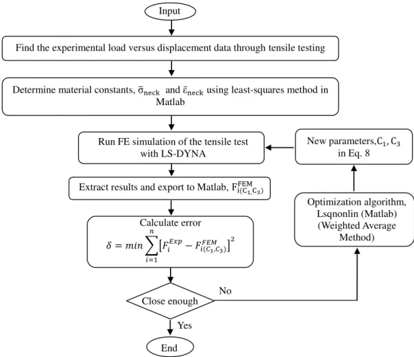
σ̅ = σ̅n k[1 + C 1 − e−C ε̅−ε̅neck ] (8) In this equation, C and C are two material constants that are obtained through the optimization algorithm described in Fig. 1, which is a flow chart that outlines the inverse method developed and applied in this work. In particular, the experimental force � versus displacement ∆ data was first extracted from the acquisition system of the tensile testing equipment. Then σ̅n k and ε̅n k were determined by using the least-squares curve fitting function in the Matlab software for the Swift hardening model. Then, the tensile test simulation was performed using LS-DYNA with initial estimates for C and C to predict the load versus displacement values, which were in turn compared with the experimental data. If the error between the predicted load-displacement values and the experimental data is below the allowable deviation, then the execution of the inverse method is stopped. Otherwise, an iterative loop with the optimization algorithm is executed using the Matlab function Lsqnonlin, which calculates new values for C and C , until the error between the predicted and experimental load-displacement values is below
the allowable deviation.
Tensile Test Procedure and the Related FE Model
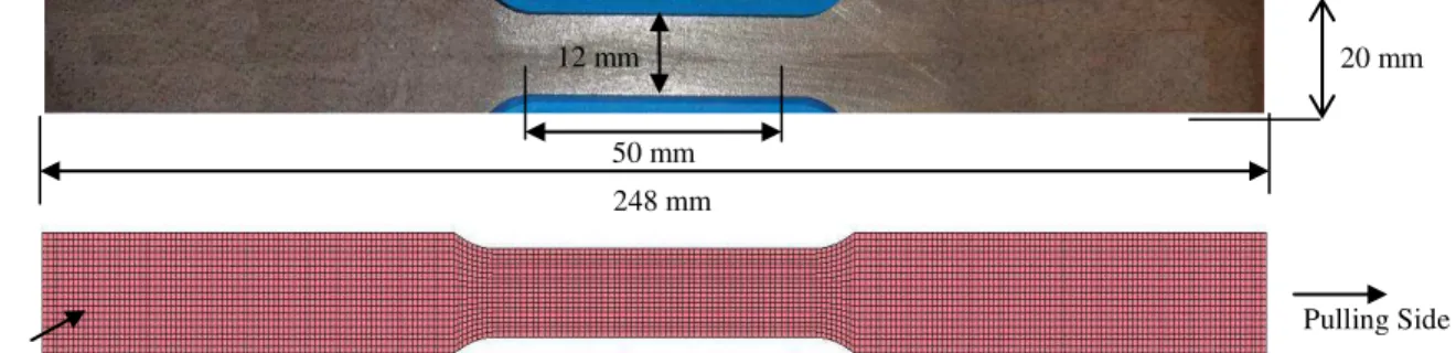
A MTS 810 machine in conjunction with a laser extensometer, as shown in Fig. 2, was used to perform the tensile tests to obtain the experimental load-displacement data for IN718 and SS 321. Fig. 3 shows the standard geometry of the tensile specimen (machined according to ASTM E8) that was used for testing. Tensile testing was conducted under ambient conditions using displacement control at a rate of 2 mm/min up to rupture.
Before necking, the true stress-true strain curve was obtained from the experimental load-displacement data using Eq. 1. Extrapolation of the true stress-true strain curve after necking was performed by employing the inverse method (Fig. 1), which requires FEM of the tensile testing process. A FE model was developed for both materials using an eight-node solid element in LS-DYNA. The total number of elements in the model was about 12,500 with three elements through the thickness. Table 1 shows the mechanical properties of both materials that were used in the FE model and Table 2 presents the Swift law work hardening constants for the IN 718 and SS 321. In the FE simulation, one end of the test specimen was fixed and the displacement was applied to the other end to represent the actual tensile testing procedure performed under displacement control. For each approach, the predicted load versus displacement curve was extracted from the FE model and compared to the experimental data.
Fig. 1Flowchart for the inverse method used in the present work No
Close enough
New parameters,C , C in Eq. 8 Find the experimental load versus displacement data through tensile testing
Determine material constants, σ̅n k and ε̅n k using least-squares method in
Matlab
Extract results and export to Matlab, Fi CM,C
Input Data
Run FE simulation of the tensile test with LS-DYNA Optimization algorithm, Lsqnonlin (Matlab) (Weighted Average Method) ≤ α ≤ 1 = � ∑[����− �� � ,�� ] � �= Calculate error End Yes
Fig. 2Experimental setup for tensile testing
Fig. 3 Specimen geometry applied for the uniaxial tensile testing and the mesh used for FEM Table 1: Mechanical properties for annealed materials
Material Elastic Modulus (GPa) Yield Strength (MPa)
IN 718 197 430
SS 321 193 258
Table 2: Swift work hardening constants for IN 718, SS 321
Results and Discussion
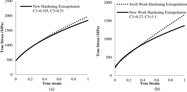
The inverse method was used to estimate the true stress–true strain curves of IN 718 and SS 321 after necking. According to the process described in Fig. 1, the optimum true stress-true strain curves were obtained by the flow relationship described in Eq. 8, and are plotted in Fig. 4 for IN 718 and SS 321. Here, these optimum curves were compared to the curves obtained by the Swift work hardening extrapolation.
The experimental load-displacement data and the predicted values using the new hardening extrapolation method are shown in Fig. 5 for 7 mm thick IN 718 and 6.2 mm thick SS 321. The simulation results, based on Eq. 8, indicate that the values of � = 0.105 and � = 6.51
Material IN 718 (7 mm thickness) 1856.5 0.61 0.107 SS 321 (6.2 mm thickness) 1514.1 0.83 0.12 12 mm 50 mm 20 mm 248 mm Fixed Side Pulling Side Laser extensometer
for IN 718 and � = 0.27 and � = 3.1 for the SS 321 predict better the true stress-true strain curve after necking.
(a) (b)
Fig. 4 Comparison of the true stress-true strain curves for the new hardening and Swift work hardening model for:
(a) IN 718 (b) SS 321
(a) (b)
Fig. 5 Comparison of the load-displacement curves for: (a) IN 718 and (b) SS 321
The results show that the true stress-true strain curves after necking can be predicted with a higher accuracy with the new hardening function developed in the present work. Therefore, knowledge of the � and � constants in Eq. 8 allow a more accurate determination of the true stress and true plastic strain distribution after necking.
It is noteworthy that a direct calculation of the local values of the strains and stresses in 0 500 1000 1500 2000 2500 0 0.2 0.4 0.6 0.8 1 Tr u e S tr ess (M Pa ) True strain
Swift Work Hardening Extrapolation New Hardening Extrapolation C1=0.105, C3=6.51 0 500 1000 1500 2000 0 0.2 0.4 0.6 0.8 1 Tr u e S tr ess (M Pa ) True Strain
Swift Work Hardening Extrapolation New Work Hardening Extrapolation C1=0.27, C3=3.1 0 10 20 30 40 50 60 70 80 0 5 10 15 20 25 Fo rc e (K N) Displacement (mm)
Swift Work Hardening New Hardening Function C1= 0.34, C3=2.81 New Hardening Function C1= 0.101, C3=6 New Hardening function C1= 0.105, C3=6.51 Experiment 0 10 20 30 40 50 0 5 10 15 20 25 30 35 Fo rc e (K N) Displacement (mm)
Swift Work Hardening New Hardening Function C1= 0.23, C3=4.05 New Hardening Function C1= 0.27, C3=3.1 Experiment
the neck region cannot be measured experimentally. Thus, without this approach, the conventional work hardening equations in the FE model would not capture the descending trend in the experimental load-displacement curve accurately and, as such, are not suitable for predicting forming limit diagrams and damage modeling of metal forming processes. So the stress and the strain distributions resulting from the inverse method are promising in evaluating more precisely the behavior of the material after necking.
Conclusions
In this work, using a new hardening function incorporated into an inverse method, the true stress-true strain behavior beyond the onset of necking for IN 718 and SS 321 was studied. The results show that this methodology can improve the accuracy of predicting the behavior of the material after necking. Specifically, for IN 718 and SS 321, the load-displacement values predicted using the new hardening law (developed in this work) were compared to that based on Swift work hardening extrapolation. This multiple comparison between both methods confirmed that the new hardening law can provide more accurate results after necking. Moreover, it should be pointed out that the validity of this method was studied for isotropic materials only and requires a separate study for anisotropic materials.
Acknowledgment
The authors would like to extend their gratitude for the funding received for this project from the Consortium for Research and Innovation in Aerospace in Quebec (CRIAQ), the Natural Sciences and Engineering Research Council of Canada (NSERC) and Fonds de recherche du Québec - Nature et technologies (FQRNT). The authors are also grateful for the technical support from NRC and, especially, M. Banu for performing tensile testing of the IN 718 and SS 321 samples. References
1. S. Cooreman et al., “Elasto-plastic material parameter identification by inverse methods: Calculation of the sensitivity matrix”, International Journal of Solids and Structures, 44 (2007), 4329-4341.
2. P. W. Bridgman, “Studies in large plastic flow and fracture”, 1952, McGraw Hill, New York. 3. Mirone, G.,“A new model for the elastoplastic characterization and the stress–strain determination on the necking section of a tensile specimen”, International Journal of Solids and Structures 13, (2004), 3545–3564.
4. Boehme et al., “Application of micromechanical material models to the evaluation of Charpy tests”, In: Giovanola, J.H., Rosakis, A.J. (Eds.), ASME Symposium Advances in Local Fracture/Damage Models for the Analysis of Engineering Problems, AMD-vol. 137. ASME, New York, 203–216.
5. Z. L. Zhang, M. Hauge, J. Odegard, C. Thaulow, “Determining true stress–strain curve from tensile specimens with rectangular cross-section”, International Journal of Solids and Structures, 36 (1999), 3497–3516.
6. S. Coppieters et al., “Identification of the post-necking hardening behaviour of sheet metal by comparison of the internal and external work in the necking zone”, Journal of Materials Processing Technology, 211 (2011), 545–552.
7. P. Koc, B. Tok, “Computer-aided identification of the yield curve of a sheet metal after onset of necking”, Computational Materials Science, 31 (2004), 155-168.
8. M. Anderson, “Tube hydroforming of aerospace alloys: Material characterization methods”, (M.Sc. Thesis, Mechanical Engineering Dep., École de Technologie Supérieure, Montréal, Canada 2010).
9. A. Considère, “Annales des Ponts et Chaussées”, (1885), IX9, 6ème série 574.
10. M. Saboori, et al., “Study of True Stress-Strain Curve after Necking for Application in Ductile Fracture Criteria in Tube Hydroforming of Aerospace Material”, ESAFORM 2012, March 14-16, 2012, Nuremberg, Germany, pp. 95-100, accepted in key Engineering Materials. 11. J.E. Hockett, O.D. Sherby, “Large strain deformation of polycrystalline metals at low homologous temperatures”, J. Mech. Phys. Solid, 23-2 (1975), 87-98.