HAL Id: hal-03229029
https://hal.archives-ouvertes.fr/hal-03229029
Submitted on 18 May 2021
HAL is a multi-disciplinary open access
archive for the deposit and dissemination of
sci-entific research documents, whether they are
pub-lished or not. The documents may come from
teaching and research institutions in France or
abroad, or from public or private research centers.
L’archive ouverte pluridisciplinaire HAL, est
destinée au dépôt et à la diffusion de documents
scientifiques de niveau recherche, publiés ou non,
émanant des établissements d’enseignement et de
recherche français ou étrangers, des laboratoires
publics ou privés.
MEMS High Temperature Gradient Sensor for
Skin-Friction Measurements in Highly Turbulent Flows
Cecile Ghouila-Houri, Abdelkrim Talbi, Romain Viard, Quentin Gallas, Eric
Garnier, Pascal Molton, Jerome Delva, Alain Merlen, Philippe Pernod
To cite this version:
Cecile Ghouila-Houri, Abdelkrim Talbi, Romain Viard, Quentin Gallas, Eric Garnier, et al.. MEMS
High Temperature Gradient Sensor for Skin-Friction Measurements in Highly Turbulent Flows.
IEEE Sensors Journal, Institute of Electrical and Electronics Engineers, 2021, 21 (8), pp.9749-9755.
�10.1109/JSEN.2020.2991785�. �hal-03229029�
Manuscript ID Draft
Manuscript Type: Selected Papers from the IEEE SENSORS 2019 Conference Date Submitted by the
Author: n/a
Complete List of Authors: Ghouila-Houri, Cecile; IEMN, ; Centrale Lille, Talbi, Abdelkrim; IEMN
Viard, ROmain; JMH Conception Gallas, Quentin; ONERA
Garnier, Eric; ONERA Molton, Pascal; ONERA Delva, Jerôme; ONERA Merlen, Alain; IEMN
Pernod, Philippe; IEMN; Centrale Lille, Keywords: APPL
Page 1 of 8 1 2 3 4 5 6 7 8 9 10 11 12 13 14 15 16 17 18 19 20 21 22 23 24 25 26 27 28 29 30 31 32 33 34 35 36 37 38 39 40 41 42 43 44 45 46 47 48 49 50 51 52 53 54 55 56 57 58 59 60
XXXX-XXXX © XXXX IEEE. Personal use is permitted, but republication/redistribution requires IEEE permission.
Abstract—This paper presents and discusses the results obtained with a MEMS (Micro-Electro-Mechanical System) high temperature gradient sensor for time-averaged and fluctuating skin-friction measurements in highly turbulent flows. Designed as a robust wall-mounted suspended hot-wire structure, the micro-sensor was made using conventional microfabrication techniques, compatible with microelectronics for designing integrated smart systems. Successfully implemented into two air wind tunnels, the sensor was tested in a large range of turbulent flows, with mainstream velocities going up to 270 m/s (Mach number of 0.79), which corresponds to the mean velocity of airliner cruise flights. The experiments demonstrated the wide dynamic range of the micro-sensor without reaching its limits. The micro-micro-sensor thereby demonstrated its value for measuring turbulence in aerodynamic applications, being particularly suitable for aeronautics.
Index Terms—Key-words alphabetic order
I. Introduction
HARACTERIZED by a disorderly behavior with vortices
whose size, location and orientation constantly vary, turbulence has been and still is a complex field of research in fluid mechanics, and this since its introduction by O. Reynolds in 1933. Aerodynamicists aim at understanding, predicting and controlling turbulence for the impacts of such research are of great interest in our society: predicting the behavior of turbulent flows in order to control and manipulate them would, in many fields of application, save energy, improve systems performances and protect the environment [1].
Submitted on Frebruary 1st 2020.
This paper comes from the same title paper presented at IEEE Sensors 2019 and is part of the “Selected Papers from the IEEE SENSORS 2019 Conference”
This work is funded by the French National Research Agency (ANR) in the framework of the ANR ASTRID “CAMELOTT” project, grant number ANR-14-ASTR-0023-01. It is supported by the regional platform CONTRAERO in the framework of the CPER ELSAT 2020 project. The authors also thank RENATECH, the French national nanofabrication network, and FEDER.
C. Ghouila-Houri, A. Talbi, Member, A. Merlen, P. Pernod are with Univ. Lille, CNRS, Centrale Lille, Yncréa ISEN, Univ. Polytechnique Hauts-de-France, UMR 8520 IEMN, F-59000 Lille, France (email: [email protected])
R. Viard was with Fluiditech, Thurmelec, Pulversheim, F-68840, France. He is now in JMH Conception Mulhouse F-68100 , France.
Q. Gallas and J. Delva are with Univ. Lille, CNRS, ONERA, Arts et Metiers Institute of Technology, Centrale Lille, UMR 9014, Laboratoire de Mécanique des fluides de Lille—Kampé de Fériet, F-59000 Lille, France
E. Garnier and P. Molton are with DAAA, ONERA The French Aerospace Lab, Meudon, F-92190, France
Transport industry is directly concerned by this field of research as it is confronted to the problem of aerodynamic drag on vehicles. For this application field, controlling turbulence means manipulating the laminar-turbulent transition of the flow around the vehicle, avoiding or suppressing the separation of the boundary layer at the rear, controlling flow instabilities impacting the vehicle structure or reducing the noise pollution… all of them in order to reduce the environmental impact of vehicles by decreasing power and fuel consumptions and limiting CO2 and NOx emissions.
The complexity of turbulence lies in the fact that it is an unresolved problem in classical physics and it does not present a simple solution. In case of simplified geometries and low Reynolds number flows, analytical solution or solutions found using numerical simulations can be found. However, targeting industrial applications means working with high Reynolds numbers flows and with complex geometries. Numerical simulations are in this case not enough to provide solutions and it is then impossible to predict the behavior of turbulence in these configurations without relying on empirical data [2]. In other words, numerical calculations need experimentations that are representative of the simulated situation (high Reynolds number flows, complex geometries).
Experimentally working in high Reynolds numbers turbulent flows generates however very short spatial and temporal scales, as reviewed in [3]: considering aeronautic applications, scales of interest present spatial scales of 100 μm or less and time scales require a bandwidth of at least 10 kHz. The need for space-and-time resolved metrology systems is thereby at stake in experimental aerodynamics. More precisely, the aerodynamicists require sensors allowing the measurement of
MEMS high temperature gradient sensor for
skin-friction measurements in highly turbulent
flows
C. Ghouila-Houri, A. Talbi, R. Viard, Q. Gallas, E. Garnier, P. Molton, J. Delva, A. Merlen, P. Pernod
C
3 4 5 6 7 8 9 10 11 12 13 14 15 16 17 18 19 20 21 22 23 24 25 26 27 28 29 30 31 32 33 34 35 36 37 38 39 40 41 42 43 44 45 46 47 48 49 50 51 52 53 54 55 56 57 58 59 608 IEEE SENSORS JOURNAL, VOL. XX, NO. XX, MONTH X, XXXX
skin-friction on models also called wall shear stress, which corresponds to the tangential viscous force of the fluid at the wall. This parameter is indeed crucial in turbulence equations along with wall pressure fluctuations.
Micro Electro Mechanical Systems (MEMS) are devices whose characteristic lengths are submillimeter meaning that they can sense the required spatial scales in fluids mechanics. In addition, downscaling leads to an increase of the sensitivity to small and fast fluctuations and is consequently suitable for addressing the time-scale challenge in fluid mechanics. MEMS sensors dedicated to fluid mechanics and aerodynamics have therefore been developed, particularly for the measurement of turbulence in reactive flow control. In 1999, Löfdahl and Gad-El-Hak published a synthesis on MEMS sensors for the study of turbulent parietal flows [4]. They presented the principles of transduction used to measure wall shear stress and pressure respectively, and compared the devices made until the end of the 1990’s. Since then, the developments have concerned geometries, structures and micro-fabrication processes and conditioning for experimental setups, but the principles of operation are still based on the same transduction mechanisms.
For the measurement of wall shear stress, these mechanisms are divided into two families: direct techniques and indirect techniques.
The first category directly measures the friction force applied to the surface through a floating element. The floating element is a mass suspended above the substrate and held by moveable tethers such as springs. The friction moves the floating element and the measurement of the displacement induces the one of wall shear stress. A recent example of such device is the capacitive sensor developed in 2011 by Chandrasekaran and co-authors, using a structure of interdigitated electrodes deposited on a membrane [5]. The capacity is evaluated by electrodes overlapping. The friction will move the membrane, which will spread the electrodes, and thus vary the capacities on both sides of the floating element. The dimensions of the device range from 3.5 μm, minimum distance between the electrodes, to 2000 μm, size of the floating element. The micro-sensor has been calibrated up to 2.9 Pa. The sensor has a dynamic response up to its resonant frequency at 6.2 kHz. However, the dimensions of the floating element are millimetric whereas the scales of friction are less than one millimeter for high Reynolds flows. The sensor is also sensitive to pressure and vibration.
The second method carries out an indirect measurement of wall shear stress. It requires an empirical or theoretical correlation to relate the measured magnitude to the shear stress. This category includes thermal sensors exploiting the heat transfer between a wire heated by an electric current and the flow: the average velocity gradient and thermal transfers near the wall are both proportional to wall shear stress. Depending on the design, the wire can be deposited on a membrane or free in the flow.
The first kind is commonly called a hot film sensor. This type of sensor is specifically designed for near-wall measurements because it is easy to mount on the surface of a wall or a model ([6]–[8]). For example, Sheplak et al., in 2002, developed, manufactured and characterized a hot film micro-sensor with dimensions of: 4 μm x 200 μm for the hot wire and 200 μm diameter for the membrane [6]. In this traditional design,
although reaching very small dimensions, they added a cavity of 10 microns under the membrane, whose pressure is close to the vacuum, in order to thermally insulate the membrane of the wall. They performed a static sensor calibration in a laminar flow, up to 1.7 Pa, and for different temperature values. The micro-sensor could also be dynamically characterized up to 20 kHz. It therefore meets the requirements of aerodynamicists in terms of spatio-temporal scale, but no test in high-speed flows has been reported in the literature. Moreover, despite the presence of the vacuum cavity to reduce heat loss, the conduction in the membrane remains significant, and the cooling of the heating wire is not only due to the forced convection with the fluid but also to the conduction in the membrane, which constitutes a measurement bias.
The second case, in which the wire is free in the flow, is regularly used in aerodynamic metrology for measuring the velocity of the flow at any point of the fluid. The sensing metal wire of the sensor is attached on extremities by two prongs, then the probe is introduced into the flow to measure the velocity. Since 2010, the University of Princeton developed a hot wire nanoprobe for turbulent flow measurements ([9], [10]). The hot wire is 130 nm thick by 2 microns wide and 60 microns long. The bandwidth of this sensor is greater than 10 kHz. The spatial and temporal resolutions reached by this sensor are fine and agree with the Kolmogorov scales. . Recently, they adapted their structure to reach supersonic flows applications [11]. At almost the same time, the IEMN also developed and patented a micro- hot wire sensor of similar design ([12]–[14]). The added value came firstly from the use of nanocrystalline diamond for the realization of prongs, as it allows a better thermal insulation, and secondly from the use of W / Pt multilayer structures to obtain a natural compensation of the stresses of the measurement wire, thus increasing the robustness of the wire, and in fact allowing operation for higher speed flows. Several micro-sensors of different sizes have been characterized. In the work of these two teams, the design is that of a conventional hot wire sensor, thus implying measurements in the flow, away from the walls.
In this paper, we present a thermal based MEMS sensor designed for high sensitive skin-friction measurements and tested in highly turbulent subsonic flows. The design of the micro-sensor is a hybrid structure reaching a compromise between conventional hot-films and hot-wires as presented above. As presented in section II, the microstructure combines free standing hot-wire, avoiding conduction in the substrate, and mechanical robustness, using suspended periodic perpendicular spports. This design enables a high temperature gradient localized in 3 μm x 1 mm area. The section III of the paper is dedicated to experimental studies performed in turbulent flows. The experiments took place in two different wind tunnels: the first one being “low-speed” up to 40 m/s, and the second done providing high-speed turbulent subsonic flows, with velocity going up to 270 m/s, corresponding to Mach number of , the Mach number being the ratio of the airflow velocity to the velocity of sound in air. The velocities considered in this second wind tunnel reach the one considered in aeronautics. Page 3 of 8 1 2 3 4 5 6 7 8 9 10 11 12 13 14 15 16 17 18 19 20 21 22 23 24 25 26 27 28 29 30 31 32 33 34 35 36 37 38 39 40 41 42 43 44 45 46 47 48 49 50 51 52 53 54 55 56 57 58 59 60
The thermal micro-sensor at stake in this paper is of hybrid design that allow to take advantages from both hot-wire and hot-film sensor structures. It indeed consists in a wall mounted robust micro-hot-wire as schematically presented in Figure 1 (a). Isolated from substrate conduction by a few micrometers deep cavity, the micro-hot-wire benefits from forced convection with the flow field boundary layer. Perpendicular micro-bridges, periodically placed along the wire, ensure the structure robustness despite a high aspect ratio, as the wire is 1 mm long for 3 µm wide and 830 nm thick. The micro-bridges are 10 µm wide for 30 µm long.
Figure 1 (b) present a Scanning Electron Microscopy image of the sensitive part of the sensor corresponding to the schematic.
Fig. 1. (a) Schematic of the wall-mounted hot-wire micro-sensor (b) SEM picture of the device (c) Zoom on the multilayered structure of the hot-wire.
As shown on both Figure 1 (a) and Figure 1 (c), another characteristic of the presented micro-sensor compared to conventional designs is the fact that heating and measurement are uncoupled. Indeed, the micro-hot-wire is a multilayer structure with on top the heater (Au layer) on which the heating current in applied, then an insulator layer (silicon dioxide) and underneath the measurement wire (Ni/Pt). This allows to uncouple heating and measurement circuits in the electronic conditioning of the micro-sensors. The regulation of the hot-wire temperature is realized by adapting the heating current depending on the temperature measurement realized on the measurement wire.
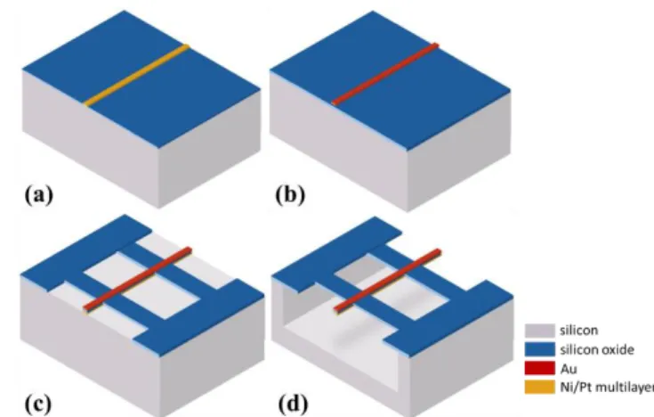
The fabrication process of the wall mounted hot wire sensor is displayed on Figure 2 and is similar to the one presented in [15] for a calorimetric micro-sensor. Given their micrometer range dimensions, the micro-sensors chips were manufactured in the IEMN cleanroom, using conventional microelectronic techniques. The devices are therefore compatible with on chip integration.
The process starts by passivating the wafer surface with silicon dioxide. A lift-off process is next used to realize the measurement wires (Figure 2 (a)). The deposition of the Ni/Pt
Enhanced Chemical Vapor Deposition is then used to deposit another passivation layer. It corresponds to the electrical insulation layer between the heater and the measurement wire. The gold heater is deposited and patterned using lift-off process again (Figure 2 (b)). Reactive Ion Etching is then exploited to etch the silicon dioxide, shaping the micro-bridges (Figure 2 (c)). The final fabrication step consists in opening the cavity using chemical vapor xenon difluoride etching process (Figure 2 (d)).
Fig. 2. Fabrication process of the micro-sensors: (a) Fabrication of the measurement wire (b) Fabrication of the heater (c) Etching of the micro-bridges (d) Opening of the cavity
Figure 3 (a) presents the finished wafer with the different micro-sensors chips separated from each other. The fabrication process and the masks used for it allow the simultaneous fabrication of more than a hundred micro-sensors on a 3 in. wafer.
Each chip is then front-side molded on a flexible packaging as presented in Figure 3 (b). This packaging allows robust integration of the micro-sensors inside wind tunnels or model, as presented in [16]. However, it presents a disadvantage: the micro-sensor in under the wall of about 100 µm which lowers the sensitivity to wall shear stress. Indeed, like conventional thermal flow sensors, the micro-sensors measure the heat transfer between the heater and the boundary layer. Its below position lowers the interaction between the thermal boundary layer of the micro-hot-wire and the fluidic boundary layer of the flow.
Fig. 3. (a) Wafer with finished micro-sensors chips (b) Micro-sensors integrated in flexible robust packaging
Characterizations performed on the micro-sensor chips demonstrated its electro-thermal performances with a temperature gradient as high as 90°C for 10 mW of power consumption [17]. We used a thermal infrared camera for evaluating the thermal profile as shown in Figure 3. The
3 4 5 6 7 8 9 10 11 12 13 14 15 16 17 18 19 20 21 22 23 24 25 26 27 28 29 30 31 32 33 34 35 36 37 38 39 40 41 42 43 44 45 46 47 48 49 50 51 52 53 54 55 56 57 58 59 60
8 IEEE SENSORS JOURNAL, VOL. XX, NO. XX, MONTH X, XXXX
microstructure is heated at 40°C for realizing the thermal image. We measured a high temperature gradient with a variation of temperature of 70°C for 7.7 mW of heating power. This imaging system also showed that the heating is confined in the 3-μm-wide wire: the thermal insulation from the substrate is successfully achieved.
Fig. 3. Thermal imaging of the micro-sensor heated with 7.7 mW and achieving 70°C of temperature variation [17]
III. TESTING IN TURBULENT BOUNDARY LAYER WIND
TUNNELS
This paper is dedicated to the experiment performed in a highly turbulent wind tunnel, with flow velocities going from low speed to high speed, up to Mach number , which corresponds to about 270 m/s in mainstream velocity. To achieve such velocity range, we performed experiments in two different wind tunnels. The wind tunnel presented in Figure 5 (a) is installed in ONERA Lille and the flow velocity can be managed between 5 and 40 m/s. In terms of Mach number, it corresponds to a maximum of 2. In the following pictures and discussion, it will be referred as “low-speed” wind tunnel when compared to the other equipment. The second wind tunnel, shown in Figure 5 (b), is referred as S8Ch in ONERA Meudon and will be referred as “high-speed” wind tunnel in the paper. This equipment is designed to work with flow velocities going from 180 m/s to 270 m/s, i.e. from to . Figure 5 (b) also displays the integration of micro-sensor in a flat plate in the wind tunnel.
Fig. 5. (a) Turbulent boundary layer “low-speed” wind tunnel in ONERA Lille (b) S8Ch “high-speed” wind tunnel in ONERA Meudon
In the low-speed wind tunnel of ONERA Lille, previous works reported the evaluation of wall shear stress in the turbulent boundary layer, using Coles-Fernholtz method ([18], [19], [16]). This method exploited the characterization of the boundary layer using a conventional motorized hot-wire probe. We calibrated the wall-mounted hot-wire micro-sensor in the wind tunnel, for time-averaged wall shear stress up to 3.2 Pa, as shown in Figure 6. The maximum current variation obtained reached more than 6 ‰.
Fig. 6. Time-averaged calibration of the wall-mounted hot-wire micro-sensor in the low-speed wind tunnel in ONERA Lille
The high-speed wind tunnel however presents velocities too high to be able to measure the local wall shear stress and the equations used in Coles Fernholtz method are not valid for high Mach number flows. Indeed, with the increased velocity, the characteristics of the fluid are changed, namely the density and the dynamic and cinematic viscosities. Also, temperature at the wall could be modified too. Therefore, this experiment focused on the physics of the wall mounted hot-wire micro sensor response with two objectives:
- first, observing the increased skin friction at the wall when increasing the flow velocity and
- second, at constant mainstream velocity, measuring different skin friction intensity depending on the position of the micro-sensor on the plate. Indeed, the wall shear stress decreases along a flat plate in turbulent boundary layer regime: it is then higher in upstream position than in downstream position
Therefore two sets of experiments were performed, one in “downstream position” as shown in Figure 7 (a) and one in “upstream position”.
Figure 7 (b) presents the results obtained during the experiments. The red results present the time-averaged measurements obtained in downstream position for a Mach number varying between 0.55 and 0.79. The micro-sensor current variation increases with high sensitivity from about 52‰ at to near 90‰ at and is thereby coherent with expected behavior. The same experiment was performed placing the micro-sensor upstream, at the beginning of the flat plate. The measured skin friction is much higher with current variation reaching about 110‰. For each value of Mach number, the upstream position measures a higher skin friction, which is in accordance with the second objective.
These results demonstrated the robustness and the
Page 5 of 8 1 2 3 4 5 6 7 8 9 10 11 12 13 14 15 16 17 18 19 20 21 22 23 24 25 26 27 28 29 30 31 32 33 34 35 36 37 38 39 40 41 42 43 44 45 46 47 48 49 50 51 52 53 54 55 56 57 58 59 60
speed flows, compatible with velocities on airliners (Mach number around 0.7 - 0.8).
Fig. 7. (a) Experimental setup of the micro-sensor inside the high-speed wind tunnel in S8Ch in ONERA Meudon (b) Results: measured time-averaged current variation with Mach number, for two different position of the micro-sensor on the flat plate, upstream and downstream.
When increasing the flow velocity from (maximum reached in the low speed wind tunnel) to
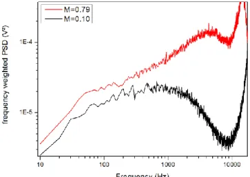
(maximum reached in the high speed wind tunnel), the fluctuating value of the wall shear stress is also increased importantly. In turbulence physics, the turbulent structures of the flow are smaller in spatial and temporal scale as the Mach number increases. Measuring the frequency weighted Power Spectral Density (PSD) allows interpretations regarding turbulent fluctuations of wall shear stress. The Welch’s method was used to obtain the PSD, with a Hamming type window.
The turbulent spectrum is characterized by a rounded shape corresponding to the turbulent energy of eddies in the flow. The energy increases up to a maximum before decreasing when the structures are small enough to suffer from viscous forces. The interval of frequency centered in the hump is characteristic of the turbulent eddies that transport energy in the flow. When the velocity regime of the flow changes, the turbulent spectrum is shifted towards higher frequencies: in other words, the turbulent structures of the flow are smaller and more energetic in high-speed flow than in low speed flows.
The wall mounted hot-wire micro-sensor demonstrated this fact as presented in Figure 8. The black curve corresponds to the turbulent spectrum measured in the low-speed wind tunnel, for 36 m/s mainstream velocity, corresponding to . In red is plotted the turbulent spectrum for (about 270 m/s of mainstream velocity), measured in the high-speed wind tunnel. The amount of turbulent energy is clearly higher on the whole range of frequencies. For a mainstream velocity of
(270 m/s), the hump is reached for 5.3 kHz. The factor between the two Mach number is also obtained between the two hump frequencies.
At more than 10 kHz however, the current electronic conditioner of the constant temperature regulation showed limitations, with a resonance peak disturbing the measurements, shown at the right of the graph of Figure 8. This limitation avoided the complete dynamic characterization of the wall mounted hot-wire micro sensor in highly turbulent flows. Nonetheless, Figure 8 is a positive first result demonstrating the micro-sensor capacity to measure fluctuations of skin friction at high velocity. Ongoing work on the electronic will expand the bandwidth of the micro-devices and future work will demonstrate the full turbulent spectrum of high-speed subsonic flows. Then, measurements in transonic and supersonic flows will be foreseen.
Fig. 8. Frequency-weighted power spectral density measured for two flow velocity regimes: one in low-speed regime, with Mach number of 0.1 and one in high-speed regime with Mach number of 0.79
IV. CONCLUSION
To conclude, this paper presented the latest achievements performed on a wall-mounted hot-wire micro-sensor designed for time-averaged and fluctuating wall shear stress measurements in highly turbulent flows. The section II presented the fabrication process of the micro-device using microelectronic compatible techniques and realized in the IEMN cleanroom. The section III described and discussed the different wind tunnel experiments performed with the micro-device.
The sensor successfully measured the mean and fluctuating wall shear stress in turbulent flows at different Mach numbers. Further work will focus on increasing the sensor sensitivity to small spatial and temporal turbulent scales for testing its response in transonic and supersonic flows.
ACKNOWLEDGMENT
This work is funded by the French National Research Agency (ANR) in the framework of the ANR ASTRID “CAMELOTT” project. It is supported by the regional platform CONTRAERO in the framework of the CPER
3 4 5 6 7 8 9 10 11 12 13 14 15 16 17 18 19 20 21 22 23 24 25 26 27 28 29 30 31 32 33 34 35 36 37 38 39 40 41 42 43 44 45 46 47 48 49 50 51 52 53 54 55 56 57 58 59 60
8 IEEE SENSORS JOURNAL, VOL. XX, NO. XX, MONTH X, XXXX
ELSAT 2020 project. The ELSAT2020 project is co-financed by the European Union with the European Regional Development Fund, the French state and the Hauts de France Region Council. The authors also thank RENATECH, the French national nanofabrication network, and FEDER.
REFERENCES AND FOOTNOTES
[1] Gad-el-Hak, « Flow Control: The Future », J. Aircr., vol. 38, no 3, p. 402‑418, 2001.
[2] L. Löfdahl et M. Gad-el-Hak, « MEMS applications in turbulence and flow control », Prog. Aerosp. Sci., vol. 35, no 2, p. 101‑203, févr. 1999, doi:
10.1016/S0376-0421(98)00012-8.
[3] N. Kasagi, Y. Suzuki, et K. Fukagata,
« Microelectromechanical Systems–Based Feedback Control of Turbulence for Skin Friction Reduction »,
Annu. Rev. Fluid Mech., vol. 41, no 1, p. 231‑251, 2009,
doi: 10.1146/annurev.fluid.010908.165221.
[4] L. Löfdahl et M. Gad-el-Hak, « MEMS-based pressure and shear stress sensors for turbulent flows », Meas. Sci.
Technol., vol. 10, no 8, p. 665, 1999.
[5] V. Chandrasekharan, J. Sells, J. Meloy, D. P. Arnold, et M. Sheplak, « A Microscale Differential Capacitive Direct Wall-Shear-Stress Sensor », J.
Microelectromechanical Syst., vol. 20, no 3, p. 622‑635,
juin 2011, doi: 10.1109/JMEMS.2011.2140356. [6] M. Sheplak, V. Chandrasekaran, A. Cain, T. Nishida, et
L. N. Cattafesta III, « Characterization of a silicon-micromachined thermal shear-stress sensor », AIAA J., vol. 40, no 6, p. 1099‑1104, 2002.
[7] J. J. Miau et al., « Mems thermal film sensors for unsteady flow measurement », Sens. Actuators Phys., vol. 235, p. 1‑13, nov. 2015, doi:
10.1016/j.sna.2015.09.030.
[8] Y. Xu, Y.-C. Tai, A. Huang, et C.-M. Ho, « IC-integrated flexible shear-stress sensor skin », J.
Microelectromechanical Syst., vol. 12, no 5, p. 740‑747,
oct. 2003, doi: 10.1109/JMEMS.2003.815831.
[9] S. C. C. Bailey et al., « Turbulence measurements using a nanoscale thermal anemometry probe », J. Fluid
Mech., vol. 663, p. 160‑179, nov. 2010, doi:
10.1017/S0022112010003447.
[10] Y. Fan, G. Arwatz, T. W. Van Buren, D. E. Hoffman, et M. Hultmark, « Nanoscale sensing devices for
turbulence measurements », Exp. Fluids, vol. 56, no 7,
juill. 2015, doi: 10.1007/s00348-015-2000-0.
[11] K. Kokmanian et al., « Development of a nanoscale hot-wire probe for supersonic flow applications », Exp.
Fluids, vol. 60, no 10, p. 150, sept. 2019, doi:
10.1007/s00348-019-2797-z.
[12] L. Gimeno, « Composant MEMS pour l’aéronautique : application au contrôle actif d’écoulements », Thèse Université Lille 1, 2009.
[13] P. Pernod et al., « Hot-wire sensor of submillimeter size and associated method of production », FR2958754 (A1) 2011-10-14 WO2011128828 (A1) 2011-10-20 FR2958754 (B1) 2012-10-26 EP2561369 (A1) 2013-02-27 US2013125644 (A1) 2013-05-23 JP2013527436 (A) 2013-06-27 US8978462 (B2) 2015-03-17
EP2561369 (B1) 04-01 DK2561369 (T3) 2015-07-06 JP5770828 (B2) 2015-08-26, 2011.
[14] A. Talbi et al., « A micro-scale hot wire anemometer based on low stress (Ni/W) multi-layers deposited on nano-crystalline diamond for air flow sensing », J.
Micromechanics Microengineering, vol. 25, no 12, p.
125029, déc. 2015, doi: 10.1088/0960-1317/25/12/125029.
[15] C. Ghouila-Houri et al., « High temperature gradient micro-sensor for wall shear stress and flow direction measurements », Appl. Phys. Lett., vol. 109, no 24, p.
241905, déc. 2016, doi: 10.1063/1.4972402. [16] C. Ghouila-Houri et al., « High temperature gradient
micro-sensors array for flow separation detection and control », Smart Mater. Struct., oct. 2019, doi: 10.1088/1361-665X/ab4be4.
[17] C. Ghouila-Houri et al., « MEMS high temperature gradient sensor for skin-friction measurements in highly turbulent flows », in 2019 IEEE SENSORS, 2019, p. 1‑4, doi: 10.1109/SENSORS43011.2019.8956802. [18] C. Ghouila-Houri et al., « High temperature gradient
calorimetric wall shear stress micro-sensor for flow separation detection », Sens. Actuators Phys., vol. 266, p. 232‑241, oct. 2017, doi: 10.1016/j.sna.2017.09.030. [19] C. Ghouila-Houri et al., « Unsteady flows
measurements using a calorimetric wall shear stress micro-sensor », Exp. Fluids, vol. 60, no 4, p. 67, mars
2019, doi: 10.1007/s00348-019-2714-5.
Cecile GHOUILA-HOURI received her MS degree in Engineering with specialization in Micro-Nanotechnology, Wave Physics and Telecommunications from Ecole Centrale de Lille in 2015 and began her PhD in November 2015, joining the ONERA, the French Aerospace Lab, and the IEMN, the Institute of Electronics, Microelectronics and Nanotechnology of Lille. After graduation in October 2018, she joined Centrale Lille as Associate Professor in September 2019 and IEMN UMR CNRS 8520 as researcher. Her research concerns the development of microsystems (micro-sensors and micro-actuators) for fluids dynamics and aeronautics applications.
Abdelkrim TALBI is Associate Professor at Centrale Lille and researcher at IMEN UMR CNRS 8520 Institute. He is a member of the International Laboratory on Critical and Supercritical phenomena in functional electronics, acoustics and fluidics (formerly LIA LICS- LEMAC). He received the MS degree in plasma, optics, electronics, and microsystems from the Universities of Metz, Nancy I, and Sup- Elec Metz, in 2000, and the PhD degree in 2003 (LPMIA) from the university of Nancy I. Researches of interest are invention, design, fabrication, characterization, and optimization of micro and nano electromechanical system (MEMS/NEMS): 1- micro-actuators (active materials), 2- micro-acoustic waves and resonant MEMS physical and bio sensors. 3- Micro-acoustic phononic crystals for sensors and microwaves applications. He has authored or coauthored of over 70 refereed publications and he is listed as co-inventor of 4 patents. Romain VIARD received his MS degree in Engineering with specialization in Micro-Nanotechnology, Wave Physics and Telecommunications from Ecole Centrale de Lille in 2006 and his PhD degree in 2010 from Ecole Centrale de Lille and the IEMN UMR CNRS 8520. During the research work presented in the paper he was at the Head of Innovation in Thurlemec Company in Pulversheim and CEO of Fluiditech. He joined in 2019 JMH Conception as R&D Engineer. His field of research concerns the development of innovative solutions for the manipulation and the measure of fluidic systems.
Page 7 of 8 1 2 3 4 5 6 7 8 9 10 11 12 13 14 15 16 17 18 19 20 21 22 23 24 25 26 27 28 29 30 31 32 33 34 35 36 37 38 39 40 41 42 43 44 45 46 47 48 49 50 51 52 53 54 55 56 57 58 59 60
Florida. Back to France, he joined the Renault group where he spent 9 years in the field of aerodynamics, using both experimental and numerical tools. In 2014, he joined ONERA, the French Aerospace Lab, in the Aerodynamics Department in Lille center, and Univ. Lille, CNRS, ONERA, Arts et Metiers Institute of Technology, Centrale Lille, UMR 9014, Laboratoire de Mécanique des fluides de Lille—Kampé de Fériet, F-59000 Lille, France. He is in charge of the "Physics of Fluids" activities. His areas of study and research cover flow control technologies, development of experimental methodologies and metrology in air and water, and terrestrial and naval aerology.
Eric GARNIER, is Dr, habilited, senior research engineer in the aerodynamics, aeroelasticity and acoustics department of ONERA. He is recognized as an expert in Large Eddy Simulation and flow control. He has contributed to 36 papers in peer-reviewed journals, 58 communications with proceedings and one textbook (LES for compressible flows with N. Adams and P. Sagaut). He has been involved in the supervision of 10 PhD Students and 8 master students. Pascal MOLTON, is research engineer in the aerodynamics, aeroelasticity and acoustics department of ONERA.
Jérôme DELVA, is research engineer in Univ. Lille, CNRS, ONERA, Arts et Metiers Institute of Technology, Centrale Lille, UMR 9014, Laboratoire de Mécanique des fluides de Lille—Kampé de Fériet, F-59000 Lille, France.
Eric GARNIER, is Dr, habilited, senior research engineer in the aerodynamics, aeroelasticity and acoustics department of ONERA. He is recognized as
Alain MERLEN is Professor Emeritus at Lille University and a former chief scientist of the fluid mechanics and energetic branch at ONERA, The French national aerospace research centre, from 2012 to 2015. He is an expert for different French research evaluation agencies: French ministry of research, French agency of research (ANR), French agency of research evaluation (AERES), and French national commission of universities (CNU). He is an expert for UE and UK Programs too. He supervised 23 PhDs, and he is author and co-author of 56 papers in peer review papers and 5 patents. He won 2 awards. He is a member of a NATO scientific Panel and a former Chaiman of the French academic society of mechanics (AUM).
Philippe PERNOD received the Engineering Degree from Centrale Lille (1986), and the MS degree in ultrasound and imaging (1986), Ph.D. degree in Electronics (1989) and the Doctorat es-Sciences (1996) from University of Valenciennes. He is currently Full Professor at Centrale Lille, Head of the AIMAN-FILMS research group of Institute of Electronics, Microelectronics and Nanotechnology and Head on french side of the International Laboratory LICS in functional electronics, acoustics and fluidics. His research interests include Nonlinear magnetoacoustics, Active multiferroic nanostructures, functional electronics, Micro-Magneto-Electro-Mechanical-Systems for sensors, actuators, microfluidics and RF devices, Nonlinear Ultrasonic imaging for the characterization of complex media and flows.
3 4 5 6 7 8 9 10 11 12 13 14 15 16 17 18 19 20 21 22 23 24 25 26 27 28 29 30 31 32 33 34 35 36 37 38 39 40 41 42 43 44 45 46 47 48 49 50 51 52 53 54 55 56 57 58 59 60
![Fig. 3. Thermal imaging of the micro-sensor heated with 7.7 mW and achieving 70°C of temperature variation [17]](https://thumb-eu.123doks.com/thumbv2/123doknet/14288147.492375/7.918.71.448.197.324/thermal-imaging-micro-sensor-heated-achieving-temperature-variation.webp)