A DISSERTATION PRESENTED TO THE UNIVERSITY OF
QUEBEC AT CHICOUTIMI IN PARTIAL FULFILLMENT
OF THE REQUIREMENTS FOR THE DOCTOR
OF PHILOSOPHY IN ENGINEERING
BY
ZHEN LI
DEVELOPMENT OF AL-MN-MG 3XXX ALLOYS FOR
APPLICATIONS AT ELEVATED TEMPERATURE
UNIVERSITE DU QUEBEC A CHICOUTIMI
THESE PRÉSENTÉ
À L'UNIVERSITÉ DU QUÉBEC ÀCHICOUTIMI COMME EXIGENCE PARTIELLE DU
DOCTORAT EN INGÉNIERIE
PAR
ZHEN LI
DÉVELOPPEMENT D’ALLIAGES D’AL-MN-MG DE LA SÉRIE
3XXX POUR DES APPLICATIONS À HAUTE TEMPÉRATURE
Abstract
The general objective of the present study is to develop a new aluminum wrought alloy which can be fabricated by conventional ingot metallurgy route for elevated-temperature applications (250°C-350°C). Al-Mn-Mg 3xxx alloys were chosen to be the base alloy. In order to improve the elevated-temperature mechanical properties, the compositions of materials need to be optimized. The influence of Mg, Si, Sc, Zr and Cu elements on the microstructure and mechanical properties at both ambient and elevated temperatures were investigated. Moreover, the nucleation mechanism of α-Al(MnFe)Si dispersoids was studied.
In this study, transmission electron microscope, scanning electron microscope and optical microscope equipped with an image analysis system were used to observe and quantitatively analyze the material microstructure. The mechanical properties at ambient temperature were evaluated by Vickers micro-hardness measurements and compression yield strength tests. The elevated-temperature mechanical properties as well as the creep properties were measured by compression yield strength tests and creep tests at elevated temperature. The results obtained were divided into following four parts.
In the first part, the effects of magnesium and silicon addition on microstructure, elevated-temperature yield strength and creep resistance of Al-Mn-Mg 3xxx alloys were investigated. Results revealed that both magnesium and silicon had an important influence on the distribution and volume fraction of precipitated dispersoids in 3xxx alloys. Without Mg or Si addition, dispersoids could hardly form during the precipitation heat treatment; hence, the alloys free of Mg or Si possessed low yield strength and creep resistance at elevated temperature. A significant improvement in elevated-temperature yield strength and creep resistance was obtained over a wide range of Mg (0.5-1.5 wt%) and Si (0.25-1 wt%) content studied due to the precipitation of a large number of dispersoids. The best combination of yield strength and creep resistance at 300 ℃ was obtained by the alloy containing 1.0 wt% Mg and 0.25 wt% Si with the maximum volume fraction of dispersoids and the minimum volume fraction of dispersoid free zone.
In the second part, the effect of metastable Mg2Si and dislocations on the formation of
α-Al(MnFe)Si dispersoids were studied by a close examination of the dispersoid precipitation process using the quench technique and TEM observation. Special attentions were paid on the nucleation mechanisms. Mg plays an important role in promoting the formation of α-Al(Mn,Fe)Si dispersoids. The number density and volume fraction of dispersoids in the Mg containing alloy are much higher than that in the Mg-free control, resulting in a strong dispersoid strengthening effect. During heating process in the Mg containing alloy, metastable Mg2Si precipitated and dissolved, leaving local Si-rich areas on pervious metastable Mg2Si,
which provide favorable nucleation sites for α-Al(Mn,Fe)Si dispersoids. It is found that β’-Mg2Si precipitates were more effective on the promotion of the dispersoid nucleation than
β’’-Mg2Si. In the deformed sample, the dislocations become the preferable sites for the
α-Al(Mn,Fe)Si dispersoid nucleation. By reducing dispersoid free zones, the dispersoid distribution became more uniform compared to the non-deformed sample. The dispersoid nucleation mechanisms based on both metastable Mg2Si and dislocations are proposed and
discussed.
In the third part, Sc and Zr were added in Al-Mn-Mg 3004 alloy to form two populations of strengthening particles (50-70 nm α-Al(Mn,Fe)Si dispersoids and 6-8 nm Al3(Sc,Zr)
precipitates) and their strengthening effects on mechanical properties and creep resistance at ambient and elevated temperatures were studied. Results showed that the microhardness and yield strength at ambient temperature greatly increased due to the Sc and Zr addition. The creep resistance at 300 ℃ significantly improved due to the precipitation of fine Al3(Sc,Zr).
However, the yield strength at 300 ℃ did not change with increasing Sc and Zr contents. The combined effects of α -Al(Mn,Fe)Si dispersoids and Al3(Sc,Zr) precipitates on the yield
strengths at 25 ℃ and 300 ℃ were quantitatively analyzed based on the Orowan bypass mechanism and the dislocation climb mechanism.
In the fourth part, the effect of Cu addition on the dispersoid precipitation, mechanical properties and creep resistance were investigated. Cu addition promotes the dispersoid precipitation by increasing the number density and decreasing the size of dispersoids.
Metastable Q-AlCuMgSi and β’-Mg2Si precipitates were observed during heating process and
both can provide favorable nucleation sites for dispersoids. The addition of Cu improves the thermal stability of dispersoids during a long-term thermal holding at 350 ºC for 500 h. Results of mechanical testing show that the addition of Cu significantly improves the hardness at ambient temperature as well as yield strength and creep resistance at 300 ºC, which is mainly attributed to the dispersoids strengthening and Cu solid solution strengthening. The yield strength contribution at 300 ºC is quantitatively evaluated based on the analytical solution.
Résumé
L’objectif général de cette thèse est de développer un nouvel alliage d’aluminium forgé pouvant être fabriqué par la méthode conventionnelle de métallurgie des lingots pour des applications à haute température (250 °C-350°C). Les alliages Al-Mn-Mg de la série 3xxx ont été sélectionnés comme base pour cette étude. Afin d’améliorer les propriétés mécaniques à haute température, les compositions de matériaux ont été optimisées. L’influence des éléments Mg, Si, Sc, Zr et Cu sur la microstructure et les propriétés mécaniques aux températures ambiantes et élevées ont donc été étudiés. De plus, le mécanisme de nucléation des dispersoïdes α-Al (MnFe) Si a été étudié.
Dans cette étude, le microscope électronique à transmission (TEM), le microscope électronique à balayage (SEM) et le microscope optique (MO), équipés de systèmes d’analyse d’images, ont été utilisés pour observer et analyser quantitativement la microstructure du matériau développé. Les propriétés mécaniques à température ambiante ont été évaluées par des mesures de microdureté Vickers et des tests de résistance à la compression. Les propriétés mécaniques ainsi que les propriétés de fluage à haute température ont été mesurées par des essais de résistance au cisaillement et des essais de fluage. Les résultats obtenus sont présentés dans les quatre sections suivantes.
Dans la première section, les effets de l’addition des éléments Mg et Si sur la microstructure, la limite d’élasticité et la résistance au fluage à température élevée des alliages 3xxx Al-Mn-Mg ont été étudiés. Les résultats ont révélé que le Mg et le Si avaient une influence importante sur la distribution et la fraction volumique des dispersoïdes précipités dans ces alliages. Sans addition de Mg ou de Si, les dispersoïdes pouvaient difficilement se former pendant le traitement thermique par précipitation; par conséquent, les alliages exempts de Mg ou Si possédaient une faible limite d’élasticité et une faible résistance au fluage à température élevée. Une amélioration significative de la limite d’élasticité et la résistance au fluage à température élevée a été obtenue sur une large gamme de Mg (0.5 à 1.5 % en poids) et de Si (0.25 à 1 % en poids) contenus, en raison de la précipitation d’un grand nombre de dispersoïdes.
La meilleure combinaison de limite d’élasticité et de résistance au fluage à 300 °C a été obtenue avec un alliage contenant 1.0 % en poids de Mg et 0.25 % en poids de Si offrant ainsi une fraction volumique maximale des dispersoïdes et une fraction de volume minimum de la zone exempte de dispersus.
Dans la deuxième section, l’effet du composé métastable Mg2Si et des dislocations sur la
formation des dispersoïdes α-Al (MnFe) Si a été étudié par un examen attentif du processus de précipitation des dispersoïdes, en utilisant la technique de trempe et l’observation au TEM. Une attention particulière a été accordée aux mécanismes de nucléation. L’élément Mg joue un rôle important en favorisant la formation de dispersoïdes de α-Al (Mn, Fe) Si. La densité et la fraction volumique des dispersoïdes dans l’alliage contenant du Mg sont beaucoup plus élevées que celles du contrôle sans Mg, ce qui entraîne un fort effet de renforcement des dispersoïdes. Pendant le processus de chauffage dans l’alliage contenant du Mg, l’élément métastable Mg2Si
a été précipité et dissous, laissant des zones riches en Si locales sur le Mg2Si métastable
perméable, fournissant ainsi des sites de nucléation favorables à l’obtention de dispersoïdes α-Al (Mn, Fe) Si. On constate que les précipités de β’-Mg2Si ont été plus efficaces à favoriser la
nucléation des dispersoïdes que le β’’-Mg2Si. Dans l’échantillon déformé, les dislocations
deviennent des sites favorisant la nucléation de dispersoïdes α-Al (Mn, Fe) Si. En réduisant les zones exemptes de dispersus, la distribution des dispersoïdes est devenue plus uniforme par rapport à l’échantillon non déformé. Des mécanismes de nucléation des dispersoïdes, basés sur l’élément métastable Mg2Si et les dislocations, sont proposés et discutés.
Dans la troisième section, les éléments Sc et Zr ont été ajoutés à l’alliage Al-Mn-Mg 3004 afin de former deux populations de particules de renforcement (dispersoïde de 50-70 nm α-Al(Mn,Fe)Si et précipités de 6-8 nm Al3(Sc,Zr) ). Leurs effets de renforcement sur les
propriétés mécaniques et la résistance au fluage à température ambiante et élevée ont été étudiés. Les résultats ont montré que la microdureté et la limite d’élasticité à la température ambiante augmentaient considérablement en raison de l’addition de Sc et Zr. La résistance au fluage à 300 °C a été considérablement améliorée en raison de la précipitation de Al3(Sc,Zr). Cependant,
combinés des dispersoïdes α-Al (Mn, Fe) Si et Al3 (Sc, Zr) précipités sur les limites d’élasticité
à 25 °C et 300 °C ont été analysés quantitativement en fonction du mécanisme de dérivation Orowan et du mécanisme d’escalade des dislocations.
Dans la quatrième section, l’effet de l’addition de l’élément Cu sur la précipitation des dispersoïdes, les propriétés mécaniques et la résistance au fluage a été étudié. L’addition de cuivre favorise la précipitation des dispersoïdes en augmentant leur densité, mais en diminuant leur taille. Les précipités métastables Q-AlCuMgSi et β’-Mg2Si ont été observés pendant le
processus de chauffage et les deux peuvent fournir des sites de nucléation favorables aux dispersoïdes. L’addition de Cu améliore la stabilité thermique des dispersoïdes lors de tenue thermique à long terme, à 350 °C pendant 500 h. Les résultats des essais mécaniques montrent que l’addition de Cu améliore significativement la dureté à la température ambiante ainsi que la résistance au choc et la résistance au fluage à 300 °C, ce qui est principalement attribué au renforcement des dispersoïdes et au renforcement de la solution solide de Cu. La contribution à la limite d’élasticité à 300 °C est évaluée quantitativement en fonction d’une solution analytique.
Acknowledgements
It is my pleasure to thank everyone who helped, encouraged and supported me during my Ph.D. study at University of Quebec at Chicoutimi (UQAC).
I would like to express my gratitude to my supervisor Professor X. Grant Chen for providing me the chance to study in Canada. He introduces me to an academic world and gives great guidance for my Ph. D study. Also, I would like to express my thanks to my co-supervisor Professor Zhan Zhang. He always inspired me to explore new possibilities and I would like to give him special thanks for the training of TEM and SEM. And also I thank Professor Sarkar Dilip, who offered me valuable courses and advice during my study. Thanks Professor Kun Liu for the valuable discussions with me.
Secondly, I would like to thank my colleagues in CURAL, Dr. Lei Pan, Dr. Cangji Shi, Dr. Ying Huang, Dr. Jian Qin, Lanfeng Jin and Peng Shen, who offered me lots of help in my life in Chicoutimi. Also I would like to thank our technicians for the support of our experiments in CURAL as Pier-Luc Prive, Dany Racine, Émélie Brideau, Alexandre Morin, Martin Bouchard. I would like to thank all my friends in CURAL for sharing summer and winter during these years with me: Dr. Emad Elgallad, Dr. Mohammad Shakiba, Dr. Zhanying Guo, Dr. Na Xu, Hezhaoye Ma, Qingfu Zhao, Jiawei Xiong, Dr. Mirza Foisal Ahmed, Anu Mohan, Jayant Barode, Xiaoming Qian, Anil Arici, Wei Xu, Chen Li, Sinan Chen, Mengyun Liu, Zhingxing Chen and Xingli Chen.
Most importantly, I could not possibly finish this work without encouragement and support from my parents and my girlfriend Jinyi Li for giving me their endless love.
Finally, thank China Scholarship Council and Dr. Chen to provide me an opportunity and award of the scholarship to support my study in Canada.
Publications
Journal papers:
1. Zhen Li, Zhan Zhang, X.-Grant Chen, Effect of magnesium on dispersoid strengthening of Al—Mn—Mg—Si (3xxx) alloys, Transactions of Nonferrous Metals Society of China. 26 (2016) 2793-2799.
2. Zhen Li, Zhan Zhang, X.-Grant Chen, Microstructure, elevated-temperature mechanical properties and creep resistance of dispersoid-strengthened Al-Mn-Mg 3xxx alloys with varying Mg and Si content. Materials Science and Engineering: A
3. Zhen Li, Zhan Zhang, X.-Grant Chen, Effect of metastable Mg2Si and dislocations on α-Al(MnFe)Si dispersoid formation in Al-Mn-Mg 3xxx alloys. (To be submitted in 2017) 4. Zhen Li, Zhan Zhang, X.-Grant Chen, Improvement of mechanical properties and creep
resistance in Al-Mn-Mg 3004 alloy with Sc and Zr addition. (To be submitted in 2017) 5. Zhen Li, Zhan Zhang, X.-Grant Chen, The influence of Cu addition on dispersoid
formation and mechanical properties of Al-Mn-Mg 3004 alloys. (To be submitted in 2017)
Poster:
1. Zhen Li, Zhan Zhang, X.-Grant Chen, The improvement of Yield strength at 25 ℃ and Creep resistance at 300 ℃ due to the addition Sc and Zr in Al-Mn-Mg-Si-Fe (3xxx) Alloys. REGAL student’s day, Montreal, Canada, September. 2017(CQRDA Award).
2. Zhen Li, Zhan Zhang, X.-Grant Chen, Effect of Cu on dispersoids and mechanical properties of Al-Mn-Mg-Si-Fe (3xxx) alloys. REGAL student’s day, Quebec, Canada, October. 2016.
3. Zhen Li, Zhan Zhang, X.-Grant Chen, The Effect of Mg2 Si on precipitation behavior of α-Al(Mn, Fe)Si dispersoids in Al-Mn-Mg-Si 3xxx alloys. REGAL student’s day, Chicoutimi, Canada, November. 2015.
4. Zhen Li, Zhan Zhang, X.-Grant Chen, The Effect of Mg on Mechanical properties and Microstructure of Al-Mn-Mg-Si-Fe (3xxx) Alloys. REGAL student’s day, Sherbrook, Canada, November. 2014.
5. Zhen Li, Zhan Zhang, X.-Grant Chen, The effect of Mg and Si on Properties and Microstructure of AA3xxx alloys. REGAL student’s day, Montreal, Canada, October. 2013.
Table of Contents
Abstract ... I Résumé ... IV Acknowledgements ... VII Publications ... VIII Table of Contents ... X List of Tables ... XIV List of Figures ... XVChapter 1 Introduction ... 1
1.1 Background ... 1
1.2 Objectives ... 2
References ... 3
Chapter 2 Literature review ... 5
2.1 Introduction of AA3xxx alloys ... 5
2.2 Microstructure of AA3xxx alloys ... 6
2.2.1 Intermetallic particles ... 6
2.2.2 Dispersoid particles ... 9
2.3 Effect of chemical composition on AA3xxx alloys ... 15
2.3.1 Mn ... 15 2.3.2 Fe... 16 2.3.3 Mg ... 17 2.3.4 Si ... 19 2.3.5 Cu ... 20 2.3.6 Sc and Zr ... 22
2.4.1 Strengthening mechanisms for yield strength at elevated temperature ... 24
2.4.2 Creep phenomenon and mechanisms at elevated temperature ... 29
References ... 33
Chapter 3 Experimental ... 42
3.1 Alloys preparation and compositions ... 42
3.1.1 The effect of Mg and Si ... 42
3.1.2 The effect of metastable Mg2Si and dislocations ... 43
3.1.3 The effect of Sc and Zr ... 43
3.1.4 The effect of Cu ... 44
3.2 Heat-treatment conditions ... 44
3.2.1 The effect of Mg and Si ... 44
3.2.2 The effect of metastable Mg2Si and dislocations ... 45
3.2.3 The effect of Sc and Zr ... 46
3.2.4 The effect of Cu ... 47 3.3 Mechanical properties ... 48 3.3.1 Microhardness ... 48 3.3.2 Electrical conductivity ... 48 3.3.3 Yield strength ... 48 3.3.4 Creep ... 48 3.4 Microstructure observation ... 49 Reference ... 49
Chapter 4 Microstructure, elevated-temperature mechanical properties and creep resistance of dispersoid-strengthened Al-Mn-Mg 3xxx alloys with varying Mg and Si contents ... 50
4.1 Introduction ... 50
4.2 Experimental ... 51
4.3 Results ... 54
4.3.2 Microstructure after heat treatment ... 55
4.3.3 Electrical conductivity and microhardness ... 63
4.3.4 Yield strength at 300℃ ... 66
4.3.5 Creep resistance at 300℃ ... 68
4.4 Discussion ... 72
4.5 Conclusions ... 75
References ... 75
Chapter 5 Effect of metastable Mg2Si and dislocations on α-Al(MnFe)Si dispersoid formation in Al-Mn-Mg 3xxx alloys ... 80
5.1 Introduction ... 80
5.2 Experimental procedures ... 81
5.3 Results and discussion ... 84
5.3.1 Precipitation of α-Al(MnFe)Si dispersoids in the base alloy ... 84
5.3.2 Precipitation of α-Al(MnFe)Si dispersoids in the M1 alloy ... 85
5.3.3 Precipitation of α-Al(MnFe)Si dispersoids in the deformed M1 alloy ... 89
5.3.4 The effect of Mg and deformation on microhardness ... 91
5.3.5 Metastable Mg2Si-based nucleation mechanism ... 93
5.3.6 Dislocation-based nucleation mechanism ... 100
5.5 Conclusions ... 104
References ... 105
Chapter 6 Improvement of mechanical properties and creep resistance in Al-Mn-Mg 3004 alloy with Sc and Zr addition ... 110
6.1 Introduction ... 110
6.2 Experimental procedure ... 112
6.3 Results and discussion ... 114
6.3.1 Microstructures in as-cast and heat-treated conditions ... 114
6.3.3 Mechanical properties at ambient and elevated temperatures ... 123
6.3.4 Quantitative analysis of yield strength at ambient and elevated temperatures ... 129
6.3.5 Prospect for the synergetic strengthening effect of co-existing α-Al(Mn,Fe)Si dispersoids and Al3(Sc,Zr) precipitates ... 136
6.4 Conclusions ... 138
References ... 138
Chapter 7 The influence of Cu addition on dispersoid formation and mechanical properties of Al-Mn-Mg 3004 alloys ... 143
7.1 Introduction ... 143
7.2 Experimental procedures ... 144
7.3 Results and discussion ... 147
7.3.1 Influence of Cu on microstructure ... 147
7.3.2 Influence of Cu on mechanical properties ... 155
7.4 Conclusions ... 162
References ... 163
Chapter 8 Conclusions and Recommendations ... 167
8.1 Conclusions ... 167
List of Tables
Table 2.1 Composition of AA3004 alloys[10] ... 5
Table 3.1 Chemical compositions of DM and DS series alloys ... 42
Table 3.2 Chemical composition of the experimental alloys ... 43
Table 3.3 Composition of SZ series alloys ... 43
Table 3.4 Composition of DU series alloys ... 44
Table 3.5 Heat-treatment conditions ... 44
Table 3.6 Heat-treatment conditions for DSZ series alloys ... 46
Table 3.7 Heat-treatment conditions for DU series alloys ... 47
Table 4.1 Chemical compositions of the experimental alloys investigated (wt%) ... 52
Table 4.2 Estimated Mg and Si contents in the solid solution after heat-treatment at 375℃/24h ... 65
Table 4.3 Grain size of different alloys in as-cast condition ... 71
Table 5.1 Chemical composition of experimental alloys (wt%) ... 82
Table 5.2 Dispersoid and DFZ parameters measured under different conditions ... 89
Table 6.1 Chemical composition of experimental alloys (wt.%) ... 112
Table 6.2 Parameters used in the calculation ... 130
Table 6.3 The yield strength contributions at 25 °C of each component (MPa) ... 132
Table 6.4 The yield strength contributions at 300 °C of each component (MPa) ... 135
Table 7.1 Chemical composition of experimental alloys (wt.%). ... 145
Table 7.3 Peak hardness values and their corresponding times and electrical conductivity .. 157
Table 7.4 The contribution of yield strength at 300 ºC by different strengthening components ... 160
List of Figures
Fig. 2.1 Backscattered SEM image of Al6(Mn,Fe) and 𝛂-Al(Mn,Fe)Si intermetallic particles 6
Fig. 2.2 Backscattered SEM images of intermetallic particles (a) in the as-cast state and
quenched from (b) 400 ℃, (c) 560 ℃ and (d) 630 ℃ during heating ... 7
Fig. 2.3 Size and number evolution of intermetallic particles ... 8
Fig. 2.4 Fraction of α-Al(Mn,Fe)Si in total amount of intermetallic particles ... 8
Fig. 2.5 SEM images which show the location of dispersoids ... 9
Fig. 2.6 (a) Selected area diffraction pattern of dispersoids precipitated after 96 h of homogenization at 300 °C and (b) computer simulated diffraction pattern of an icosahedral quasicrystal phase showing five-fold symmetry ... 10
Fig. 2.7 TEM images showing the morphology of dispersoids precipitated during heating, (a) 350 °C, (b) 400 °C, (c) 500 °C and (d) 580 °C ... 11
Fig. 2.8 The evolution of the size and number density of dispersoids ... 12
Fig. 2.9 The phase diagram of Al-Mn alloys of the Al-rich part ... 15
Fig. 2.10 The yield strength at 300 °C of AA3xxx alloys with 0.1%Fe, 0.3% and 0.6%Fe .... 16
Fig. 2.11 The creep strain curve measured at 300 °C of AA3xxx alloys with 0.1%Fe, 0.3% and 0.6%Fe ... 17
Fig. 2.12 Phase diagram of Al-Mg Alloys ... 18
Fig. 2.13 (a) TEM image of dispersoid nucleated on the surface of u-phase (b) a model of the precipitation of the dispersoids ... 19
Fig. 2.14 Backscattered SEM image after 1 h at 500 °C with 20°C/s heating rate revealing the eutectoid transformation of Al6(Mn, Fe) into α-Al(Mn,Fe)Si. ... 20
Fig. 2.15 Comparison of chemical composition between an elemental map and EDS for the same precipitate (a) Cu-L map, (b) estimated chemical compositions from elemental maps, (c) a zero-loss image, and (d) EDS data obtained for a precipitate of (c). ... 22 Fig. 2.16 TEM dark-field images showing the Al3(Sc,Zr) precipitates in an Al-B4C
composite: (a) initial peak aging (350 ◦C/10 h), (b) 2000 h annealing at 300 ◦C, (c) 1000 h annealing at 350 ◦C and (d) 2000 h annealing at 350 ◦C. ... 23 Fig. 2. 17 (a) Dark field image of a precipitate in ternary Al–Sc–Zr. The image was obtained close to the 001 zone axis. (b) Composition profile along the line indicated in (A) showing the number of EDS counts under the Sc Kα and Zr Kα peaks as a function of position ... 24 Fig. 2.18 Theoretical calculation of yield stresses based on the models of dislocation climb and Orowan mechanisms for an Al-B4C composite with 0.24 vol.% Al3Sc at 300°C as a
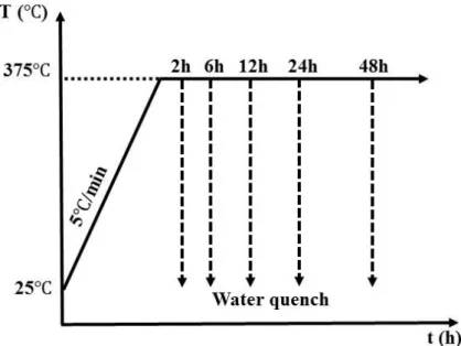
function of precipitate radius. ... 25 Fig. 2.19 A dislocation bypasses impenetrable particles, shown schematically. The external stress increases from left to right ... 26 Fig. 2.20 Geometry of general climb model, showing an edge dislocation with segment CD in the glide plane and segment AC climbing over a particle ... 27 Fig. 2.21 Schematic models of solid solutions: substitutional solid solution and interstitial solid solution [68] ... 28 Fig. 2.22 Typical creep curve showing the three steps of creep [70]. The dotted line shown in the figure is for the compression creep curves... 30 Fig. 2.23 Ashby deformation map of silver. A – Dislocation glide creep, B – Dislocation creep, C – Coble creep, D – Nabarro-Herring creep, E – Elastic deformation ... 31 Fig. 3.1 The schematic diagram of heat treatment condition for DM series and DS series alloys ... 45 Fig. 3.2 the schematic diagram of the various heat treatment conditions: (a) program A and B, (b) program C. ... 46
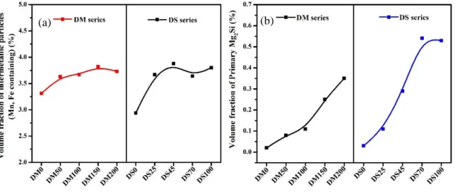
Fig. 3.3 The schematic diagram of heat treatment condition for SZ series alloys ... 47 Fig. 3.4 The schematic diagram of the various heat treatment conditions: (a) heat treatment at 375 ℃, 425 ℃ and 475 ℃, (b) heat treatment for the study of dispersoids precipitation process... 47 Fig. 4.1 As-cast microstructure of (a) DM0 alloys (0% Mg) and (b) DM100 alloys (1.0% Mg). ... 55 Fig. 4.2 Volume fraction of Mn-, Fe-containing intermetallic particles (a) and primary Mg2Si
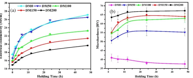
particles (b) of the as-cast samples. ... 55 Fig. 4.3 Distribution of the dispersoid zone and DFZ in the DM series (a) DM0 alloy (0% Mg), (b) DM50 alloy (0.47%% Mg), (c) DM100 alloy (1.00% Mg) and (d) DM200 alloy (2.02% Mg). ... 57 Fig. 4.4 Distribution of the dispersoid zone and DFZ in the DS series (a) DS0 alloy (0% Si), (b) DS25 alloy (0.23% Si), (c) DS45 alloy (0.42%Si) and (d) DS100 alloy (0.97% Si). ... 58 Fig. 4.5 Volume fraction of the dispersoid zone and DFZ in the DM and DS alloy series. .... 58 Fig. 4.6 TEM images of dispersoid distribution in the DM series: (a) DM0 (0% Mg), (b) DM50 (0.47%% Mg), (c) DM100 (1.00% Mg), (d) DM150 (1.50% Mg) and (e) DM200 (2.02% Mg). ... 61 Fig. 4.7 TEM images of dispersoid distribution in the DS series: (a) DS0 (0% Si), (b) DS25 alloy (0.23% Si), (c) DS45 (0.42% Si), (d) DS70 (0.70%) and (e) DS100 (0.97%Si). ... 63 Fig. 4.8 Equivalent diameter (a) and number density (b) of disperoids in the DM and DS series. ... 63 Fig. 4.9 Volume fraction of dispersoids in the DM and DS series. ... 63 Fig. 4.10 Electrical conductivity (a) and microharness (b) as a function of holding time at 375 ℃ in the DM series. ... 66
Fig. 4.11 Electrical conductivity (a) and microharness (b) as a function of holding time at 375 ℃ in the DS series. ... 66 Fig. 4.12 Evolution of yield strength measured at 300 ℃ in the DM and DS series. ... 68 Fig. 4.13 Typical creep curves in the DM and DS series. ... 70 Fig. 4.14 Total creep strain (a) and the minimum creep rate (b) of different alloys in the DM and DS series... 70 Fig. 4.15 TEM image of DM100 alloy after the creep test demonstrating the pinning effect of dispersoids on dislocations. ... 71 Fig. 4.16 EBSD images of grain structure (a) DM50 alloys (0.47%Mg) and (b) DM200 alloys (2.02%Mg) in as-cast condition. ... 71 Fig. 4.17 TEM images of the water-quenched DM100 sample: (a) after heating to 275 ℃ and (b) after heat-treated at 375℃/2h. The red dash lines in (b) indicate the <001>Al direction. .. 73
Fig. 5.1 Schematic diagram of various heat treatments (a) procedure A and (b) procedure B (two-step heat treatment). ... 83 Fig. 5.2 Optical images showing the dispersoid distribution in the base alloy, (a) 375 ºC for 24 h and (b) 375 ºC for 72 h... 85 Fig. 5.3 TEM bright field images showing the dispersoids in the base alloy, (a) 375 ºC for 24 h and (b) 375 ºC for 72 h, recorded near [001]Al zone axis. ... 85
Fig. 5.4 Optical images showing the precipitation of dispersoids in the M1 alloy under
different heat treatment conditions, (a) 375ºC/24h, (b) 175ºC/5h + 375/24h and (c) 250ºC/2h + 375 ºC/24h. ... 87 Fig. 5.5 TEM bright field images showing the dispersoids in the M1 alloy after different heat treatments, (a) 375ºC/24h, (b) 175ºC/5h + 375ºC/24h and (c) 250ºC/12h + 375ºC/24h,
Fig. 5.6 Optical image showing the precipitation of dispersoids in the deformed M1 alloy after heat treatment at 375ºC/24h: (a) the dense dispersoid zone and the less dense dispersoid zone and (b) enlarged image of (a). ... 91 Fig. 5.7 TEM bright field images showing the dispersoids in the deformed M1 alloy (0.2 strain + 375oC/24h), a) in the dense dispersoid zone and b) in the less dense dispersoid zone. ... 91 Fig. 5.8 Microhardness of the base alloy and M1 alloy under various experimental conditions. ... 92 Fig. 5.9 The precipitation process in the M1 alloy (a) as-heated at 275 ºC, (b) as-heated at 375 ºC, (c) 375 ºC for 30 min, (d) 375 ºC for 1 h, (e) 375 ºC for 2 h. ... 95 Fig. 5.10 TEM analysis of the M1 sample held at 375ºC for 15 minutes showing the local Si enrichment on the sites of previous 𝛃’-Mg2Si precipitates, (a) TEM image on the site of a
previous 𝛃’-Mg2Si and the position of the line scanning (A-C) and (b) Si distribution along
the line A-C. ... 96 Fig. 5.11 TEM images of the M1 samples experienced (a) 175ºC for 5 h, (b) 250 ºC for 12 h, (c) 175ºC for 5 h + 375 ºC for 1 h, (d) 250ºC for 12 h + 375ºC for 1 h, (e) SADP
corresponding to the samples after heat-treatment 175ºC for 5 h, (f) SADP corresponding to the samples after heat-treatment 250ºC for 12 h. ... 98 Fig. 5.12 Schematic diagram of the dispersoid formation based on metastable Mg2Si
nucleation mechanism, (a) metastable Mg2Si precipitated, (b) Mg2Si dissolved forming
Si-rich areas and (c) 𝛂-Al(MnFe)Si disperspoid nucleation and growth in the Si-rich sites of previous metastable Mg2Si along the <001>Al direction. ... 100
Fig. 5.13 The precipitation process in the deformed M1 samples (a) heated to 275 ºC showing dislocations, recorded near [011]Al; (b) heated to 275 ºC showing 𝛃’-Mg2Si, recorded near
[001]Al; (c) held at 375 ºC for 1 h, recorded near [011]Al, (d) held at 375 ºC for 1 h, recorded
Fig. 5.14 Schematic diagram of the dislocation-based nucleation mechanism of
𝛂-Al(MnFe)Si dispersoids in the deformed sample, (a) metastable Mg2Si precipitated and
co-existed with dislocations; (b) metastable Mg2Si dissolution and Si and Mn diffusion along
dislocations and (c) 𝛂-Al(MnFe)Si dispersoid nucleation and growth on dislocations
including in the Mn depleted zone (formerly the DFZ). ... 104 Fig. 6.1 As-cast microstructure of (a) SZ0, (b) SZ15 and (c) SZ30 alloys ... 115 Fig. 6.2 Volume fraction of Mn-containing intermetallics and primary Mg2Si particles of
three alloys ... 115 Fig. 6.3 Optical images after heat treatment at 375°C/24h (etched by 0.5% HF): (a) SZ0, (b) SZ15 and (c) SZ30 alloys ... 117 Fig. 6.4 Volume fraction of the dispersoid zone and DFZ of three alloys after heat treatment at 375°C/24h ... 117 Fig. 6.5 TEM images of α-Al(Mn,Fe)Si dispersoids (a) SZ0, (b) SZ15 and SZ30 alloys ... 120 Fig. 6.6 (a) the equivalent diameter and number density of α-Al(Mn,Fe)Si dispersoids, (b) the volume fraction of α-Al(Mn,Fe)Si dispersoids of three alloys ... 120 Fig. 6.7 Centered dark field TEM images of Al3(Sc,Zr) precipitates (a) SZ15 alloy after
300°C/12h, (b) SZ15 alloy after 375°C/24h, (c) SZ30 alloy after 300°C°/12h, (d) SZ30 alloy after 375°C/24h ... 121 Fig. 6.8 The equivalent diameter of Al3(Sc,Zr) precipitates of two alloys at two heat treatment
conditions ... 122 Fig. 6.9 TEM images showing both α-Al(Mn,Fe)Si dispersoids and Al3(Sc,Zr) in the
aluminum matrix of SZ15 Alloy, (a) bright field TEM image and (b) dark field TEM image captured slightly off the center of {100} superlattice reflections of the Al3(Sc,Zr) precipitates.
Fig. 6.10 TEM images of the particle free zone along the grain boundary in SZ15 alloy, (a) bright field TEM image and (b) dark field TEM image captured slightly off the center of {100} superlattice reflections of Al3(Sc,Zr) precipitates. ... 123
Fig. 6.11 Microhardness evolution of the three alloys as a function of holding time during heat treatment at (a) 300 °C and (b) 375 °C ... 124 Fig. 6.12 Yield strengths (a) at 25°C and (b) at 300 °C for two heat treatment conditions ... 126 Fig. 6.13 Typical creep cures of SZ0, SZ15 and SZ30 alloys, conducted at 300 °C for 96 h with a load 58 MPa ... 128 Fig. 6.14 Logarithmic plots of the minimum creep rate as a function of applied stress to determine the threshold stress 𝛔𝐭𝐡 (a) and logarithmic plots of the minimum creep rate as a function of effective stress to determine the true stress exponent 𝐧𝐭 (b) ... 129 Fig. 6.15 The comparison between calculated and experimentally measured yield strengths at 25 °C. ... 133 Fig. 6.16 The comparison between calculated and experimentally measured yield strengths at 300 °C. ... 136 Fig. 7.1 The schematic diagram of two heat treatment conditions: (a) for the precipitation of dispersoids and (b) for the dispersoid nucleation. ... 145 Fig. 7.2 Typical as-cast microstructures of (a) DU0 alloy and (b) DU120 alloy. ... 147 Fig. 7.3 The volume fractions of intermetallic particles in four experimental alloys. ... 148 Fig. 7.4 Optical images of (a) DU0 alloy and (b) DU120 alloy after heat-treatment at 425 ºC for 6 h. ... 149 Fig. 7.5 The volume fractions of the dispersoid zone and dispersoid free zone (DFZ) in the experimental alloys. ... 149
Fig. 7.6 TEM bright field images of dispersoids after heat-treated at 425 ºC for 6 h (a) DU0 alloy (0% Cu), (b) DU35 alloy (0.37% Cu), (c) DU75 alloy (0.72% Cu) and (d) DU120 alloy (1.23% Cu). ... 150 Fig. 7.7 (a) the equivalent diameter and number density of dispersoids and (b) the volume fraction of dispersoids in the experimental alloys. ... 151 Fig. 7.8 TEM images of as-heated 330 ºC samples of (a) DU0 alloy and (b) DU120 alloy. . 152 Fig. 7.9 The chemical composition of Q-phase in DU120 alloy. ... 152 Fig. 7.10 TEM images of as-heated 425 ℃ samples of (a) DU0 and (b) DU120 alloys. ... 153 Fig. 7.11 TEM images of dispersoids after holding at 350 ºC for 500 h in (a) DU0 alloy and (b) DU120 alloy. ... 154 Fig. 7.12 The comparison of the dispersoid size before and after a long-term thermal holding at 350ºC/500h. ... 155 Fig. 7.13 Microhardness of experimental alloys as a function of holding time at (a) 375 ºC, (b) 425 ºC and (c) 475 ºC. ... 157 Fig. 7.14 Yield strength at 300 ºC of experimental alloys after heat treatment at 425ºC/6h. 158 Fig. 7.15 The comparison of the yield strength at 300 ºC between calculated and
experimentally measured ones ... 161 Fig. 7.16 Typical creep curves of four experimental alloys ... 162
Chapter 1 Introduction
1.1 Background
Nowadays, the growing demand for high performance and lightweight structural components at elevated temperatures (250 to 350℃ ) is a challenge for weight-sensitive automotive and aerospace industry. The traditional precipitation-strengthened aluminum alloys such as 2xxx, 6xxx and 7xxx can hardly meet the requirement of elevated-temperature mechanical properties, because of the rapid coarsening of nano-scale precipitates at elevated temperature (overaging effect) [1, 2]. In recent years, the dispersoid strengthening in AA3xxx aluminum alloys has been discovered, and the mechanical properties at both room and elevated temperatures could be greatly improved [3-7]. Moreover, α-Al(MnFe)Si dispersoids as the main strengthening phase in AA3xxx alloys have been proved to be thermally stable at elevated temperature [5, 6]. In addition, AA3xxx alloys possess good formability, excellent corrosion resistance and weldability [8, 9]. The combination of those properties makes AA3xxx alloys especially attractive for elevated temperature applications.
Until now, limited open literatures are available on the effect of chemical composition on microstructure and elevated-temperature mechanical properties in AA 3xxx alloys. Muggerud et al [4] studied the effect of Mn and Si on the evolution of dispersoids in AA3003 alloy. It is found that the addition of Mn and Si can promote the precipitation of α-Al(MnFe)Si dispersoids and thus improve room-temperature mechanical properties. The effect of Fe on the dispersoid precipitation and elevated-temperature properties in AA3004 alloy was investigated by Kun et al [6]. With an optimum Fe content, a higher volume fraction of α-Al(MnFe)Si dispersoids and hence a better mechanical properties and creep resistance at elevated temperature can be achieved.
In the present study, the research focused on the effect of Mg, Si, Cu, Sc and Zr elements on the microstructure and elevated-temperature mechanical properties of AA3xxx alloys.
1.2 Objectives
The general objective of this project is to develop a new wrought alloy which can be used for elevated-temperature applications (250℃-350℃). In the present study, Al-Mn-Mg 3xxx alloy were chosen to be the base alloy. In order to improve the elevated-temperature mechanical properties, the compositions of materials need to be optimized. The research was divided into following four parts with specific objectives.
1. The effect of Mg and Si on microstructure and properties at ambient and elevated temperatures
The amounts of Mg and Si are optimized to improve the mechanical properties at ambient and elevated temperatures.
2. The nucleation mechanisms of dispersoids
The study involves the relationship between metastable Mg2Si and α-Al(Mn,Fe)Si
dispersoids and the effect of deformation on the nucleation of the dispersoids. The goal is to clarify the nucleation mechanisms of α-Al(Mn,Fe)Si dispersoids under the influences of metastable Mg2Si and pre-deformation.
3. The effect of Sc and Zr on microstructure and properties at ambient and elevated temperatures
In order to study the combined action of Al3(Sc, Zr) precipitates and α-Al(Mn,Fe)Si
dispersoids on the mechanical properties at elevated temperature, Sc and Zr elements will be added to AA3xxx alloys.
4. The effect of Cu on microstructure and properties at ambient and elevated temperature With the addition of Cu, the effect of Cu on the precipitation behavior of dispersoids and elevated-temperature mechanical properties is investigated.
References
1. I. J. Polmear, M. J. Couper, Design and development of an experimental wrought aluminum alloy for use at elevated temperatures, Metallurgical Transactions A. 19 (1988) 1027-1035. Doi: http://dx.doi.org/10.1007/BF02628387.
2. Y. Zhou, Z. Liu, S. Bai, P. Ying, L. Lin, Effect of Ag additions on the lengthening rate of Ω plates and formation of σ phase in Al-Cu-Mg alloys during thermal exposure,
Materials Characterization. 123 (2017) 1-8. Doi:
http://dx.doi.org/10.1016/j.matchar.2016.11.008.
3. Y. J. Li, A. M. F. Muggerud, A. Olsen, T. Furu, Precipitation of partially coherent α-Al(Mn,Fe)Si dispersoids and their strengthening effect in AA 3003 alloy, Acta Materialia. 60 (2012) 1004-1014. Doi: http://dx.doi.org/10.1016/j.actamat.2011.11.003. 4. A. M. F. Muggerud, E. A. Mørtsell, Y. Li, R. Holmestad, Dispersoid strengthening in
AA3xxx alloys with varying Mn and Si content during annealing at low temperatures, Materials Science and Engineering: A. 567 (2013) 21-28. Doi:
http://dx.doi.org/10.1016/j.msea.2013.01.004.
5. K. Liu, X. G. Chen, Development of Al–Mn–Mg 3004 alloy for applications at elevated temperature via dispersoid strengthening, Materials & Design. 84 (2015) 340-350. Doi:
http://dx.doi.org/10.1016/j.matdes.2015.06.140.
6. K. Liu, X.-G. Chen, Evolution of Intermetallics, Dispersoids, and Elevated Temperature Properties at Various Fe Contents in Al-Mn-Mg 3004 Alloys, Metallurgical and Materials Transactions B. 47 (2016) 3291-3300. Doi: http://dx.doi.org/10.1007/s11663-015-0564-y.
7. K. Liu, H. Ma, X. G. Chen, Enhanced elevated-temperature properties via Mo addition in Al-Mn-Mg 3004 alloy, Journal of Alloys and Compounds. 694 (2017) 354-365. Doi:
8. H.-W. Huang, B.-L. Ou, Evolution of precipitation during different homogenization treatments in a 3003 aluminum alloy, Materials & Design. 30 (2009) 2685-2692. Doi:
http://dx.doi.org/10.1016/j.matdes.2008.10.012.
9. A. R. Yazdzad, T. Shahrabi, M. G. Hosseini, Inhibition of 3003 aluminum alloy corrosion by propargyl alcohol and tartrate ion and their synergistic effects in 0.5% NaCl solution, Materials Chemistry and Physics. 109 (2008) 199-205. Doi:
Chapter 2 Literature review
2.1 Introduction of AA3xxx alloys
Due to their relatively low cost, workability, and excellent corrosion resistance [1, 2], traditional AA3xxx series aluminum alloys are widely used in the industrial production, such as architecture, packaging and automobile.
However, the good elevated-temperature properties of AA3xxx alloys are often ignored. Nowadays, the growing demand for high performance and lightweight structural components at elevated temperatures (250 to 350℃) is a challenge for weight-sensitive automotive and aerospace industries. The traditional precipitation-strengthened aluminum alloys such as 2xxx, 6xxx and 7xxx can hardly meet the requirement of elevated-temperature mechanical properties, because of the rapid coarsening of nano-scale precipitates at elevated temperature (over-aging effect) [3, 4]. In recent years, the dispersoid strengthening in 3xxx aluminum alloys that can improve the mechanical properties at both room and elevated temperatures has been discovered [5-9]. Although Al-Mn-Mg 3xxx alloys are traditionally classified as non-heat-treatable alloys, the precipitation of thermally stable α-Al(MnFe)Si dispersoids during heat treatment and hence the improvement of high temperature properties in 3004 alloy have been recently reported [7, 8]. The combination of those properties makes 3xxx alloys especially attractive for elevated-temperature applications. Therefore, in the present study, the development of the new alloys was on the basis of AA3004 alloy. The composition of AA3004 alloy is shown in Table 2.1.
Table 2.1 Composition of AA3004 alloys[10]
Mn Si Fe Cu Mg Al
2.2 Microstructure of AA3xxx alloys
2.2.1 Intermetallic particles
Serval studies have been conducted on the microstructure evolution during different heat treatments in 3xxx alloys, mainly focusing on 3003 and 3004 alloys [1, 5-8, 11-20] . The as-cast microstructure of 3003 and 3004 alloys consist of mainly Al6(Mn,Fe), α-Al(Mn,Fe)Si and
Mg2Si intermetallic phases [12, 17, 18, 21-23]. During solidification, constituent particles
Al6(Mn,Fe) and α-Al(Mn,Fe)Si formed in interdendritic arm spaces or along grain boundaries.
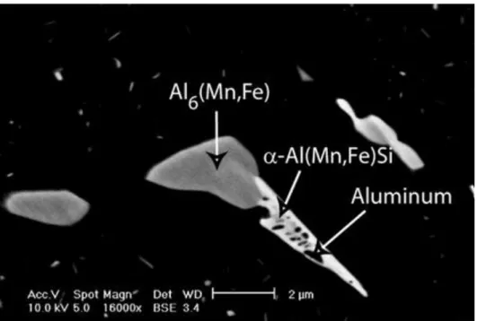
The constituent particles are originally eutectic particles that distributed in the interdendritic regions during solidification. Upon the homogenization treatment, morphology of those constituent particles changes with a possible phase transformation of Al6(Mn,Fe) phase to
α-Al(Mn,Fe)Si as shown in Fig. 2.1[17].
Fig. 2.1 Backscattered SEM image of Al6(Mn,Fe) and α-Al(Mn,Fe)Si intermetallic particles
The solidification microstructure of 3xxx alloys is shown in Fig. 2.2, a large amount of rod like, plate like and eutectic intermetallic particles are distributed in the interdendritic
regions and grain boundaries. Most of the intermetallic particles have been determined to be Al6(Mn, Fe) and only a small fraction of primary particles are determined to be α-Al(Mn,Fe)Si.
Fig. 2.2 Backscattered SEM images of intermetallic particles (a) in the as-cast state and quenched from (b) 400 ℃, (c) 560 ℃ and (d) 630 ℃ during heating
In the previous work [12], the evolution of the size and number density of intermetallic particles was studied, as shown in Fig. 2.3 [12]. as the temperature went up, the number density of intermetallic particles increased, in the other word, the eutectic networks of intermetallic particles breaked up which can be seen in Fig. 2.2 (a)-(c). However, if the temperature was over 550 ℃ , the number density would drop sharply and the diameter increased which indicated that coarsening was the main mechanism to control the evolution of primary, as is shown in Fig. 2.2 (d).
Fig. 2.3 Size and number evolution of intermetallic particles
As is shown in Fig. 2.4 [12], when temperature increased, intermetallic particles Al6(Mn,
Fe) started to transform into α-Al(Mn,Fe)Si, the fraction of α-Al(Mn,Fe)Si increased shapely with temperature. The transformation process from Al6(Mn,Fe) to α-Al(Mn,Fe)Si is identified
as a eutectoid process in which the Al6(Mn,Fe) phase decomposes to a mixture of
α-Al(Mn,Fe)Si and aluminum solid solution. The decomposition preserves the local volume and content of iron and manganese (which diffuse slowly) [22], but requires intake of silicon. The silicon appears to diffuse from the matrix.
2.2.2 Dispersoid particles
During heat treatment, a considerable number of α-Al(Mn,Fe)Si dispersoids precipitate and the size and amount of dispersoids are dependent on the alloy chemistry and heat treatment condition [5-7, 11, 19]. The dispersoids mainly distribute in the corns of dendrite arms. The area with a large number density of dsipersoids can be defined as the dispersoid zone. On the other hand, very few dispersoids precipitated in the grain boundaries and the interdendritic areas. These locations are defined as the dispersoid free zone (DFZ). All the dispersoid free zones locate in the Mn depleted areas formed during solidification[13], so the cause of dispersoid free zone is the segregation of Mn elements. Due to the large scale of dispersoid zone and dispersoid free zone, TEM cannot be used for observation. The dispersoid zone and dispersoid free zone can be observed using optical microscope and SEM with etched samples. The morphology is shown in Fig. 2.5 [17].
Fig. 2.5 SEM images which show the location of dispersoids
The α-Al(Mn,Fe)Si dispersoids are partially coherent with the matrix [5, 24] and has a cubic crystal structure [11]. The diffraction pattern of dispersoids is shown in Fig. 2.6 [11]. The precipitation of α-Al(Mn,Fe)Si dispersoids starts from approximately 340 ℃ [7]. After a
proper heat treatment, the maximum volume fraction can reach as high as ~3% and the dispersoids are proved to be thermally stable at 300 ℃, resulting in excellent mechanical properties and creep resistance at 300 ℃ [7]. During heating, α-Al(Mn,Fe)Si dispersoids precipitate from the matrix. Two dispersoid morphologies were observed: spherical shape and rodlike shape as shown in Fig. 2.7 [11]. The size of most dispersoids is in the range of 50-200 nm.
Fig. 2.6 (a) Selected area diffraction pattern of dispersoids precipitated after 96 h of homogenization at 300 °C and (b) computer simulated diffraction pattern of an icosahedral quasicrystal phase showing five-fold symmetry
Fig. 2.7 TEM images showing the morphology of dispersoids precipitated during heating, (a) 350 °C, (b) 400 °C, (c) 500 °C and (d) 580 °C
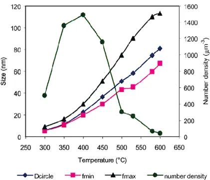
As the annealing temperature increases, the number density of dispersoids first increases and then decreases. For 3003 alloys, at 400 ℃ the number density reaches the maximum point and most of the dispersoids dissolve in the matrix at 600 ℃, however, for other 3xxx alloys, the temperature and heating time are affected greatly by the chemical composition of alloys. The size of despersoids increases with heating temperature and heating time. Fig. 2.8 [11]
shows the evolution of size and number density of dispersoids as a function of heat treatment temperature..
Fig. 2.8 The evolution of the size and number density of dispersoids
Determination of the volume fraction of dispersoids is experimentally challenging, as the size of dispersoids is too small for optical or SEM microscopes. Transmission electron microscope must be used for the observation of dispersoids in details. However, due to the non-uniform distribution of dispersoids, many micro-scale dispersoid free zones presented in the microstructure. Because of the large scale, the observation and quantification of the dispersoid free zone are not possible for TEM.
Previous work by Li [11] and Dehmas [17] presented two methods to determine the volume fraction of dispersoids by TEM. Both of them use optical microscope to quantity the volume fraction of the dispersoid free zone by analyzing the etched sample. For quantitatively study of the morphology and size of dispersoids, TEM images are recorded.
In the work of Dehmas [17], the volume fraction of the dispersoids in the dispersoid zone is calculated by assuming a disc-shape morphology, with a mean diameter equal to d and a
thickness equal to d/2, where d is the equivalent diameter. So the volume fraction of the dispersoids in the dispersoid zone can be then expressed as:
Vint(pct)= π/8 ∙d3∙ Nint⋅100 Eq. 2.1
Where Nint(pct) is the volume number density of the dispersoids in dispersoid zone, and d is the mean diameter calculated by TEM images.
When the volume fraction of the dispersoid free zone is taken into account, the volume number density in the alloy is calculated as:
Nv(pct)= Nint(1-P) Eq. 2.2
Where P is the volume fraction of the dispersoid free zone including intermetallic particles. The dispersoid volume fraction in the alloy can thus be expressed as:
Vint(pct)= π/8 ∙d3∙ Nv⋅100 Eq. 2.3
The other method is presented in the study of Li [11]. The dispersoids are assumed as rectangular parallelepipedic particles with length a, width b and height c, randomly distribute in the thin foil without overlapping, the average projected area of these particles in the film is:
A = 1/2(ab + bc + ac) Eq. 2.4
The average equivalent diameter of dispersoids projected on the film, D, can be calculated by the following equation:
D2=2a2
Where, k1=b/a, k2=c/a , 0< k1<1, 0< k2<1.
The shape factor K can be calculated as:
K=V
AD=
√2πk1k2
(k1+k2+k1k2)3/2 Eq. 2.6
Then the volume fraction can be calculated as:
VV=∑ni=1AiADiKi/t Eq. 2.7
Where AiA, Di and Ki are projected area fraction, average equivalent diameter, and shape
factor of dispersoids respectively, and t is the thickness of TEM foil. The influences of overlapping and truncation by foil surface is not considered. Since the thickness of the TEM foil for AA3xxx alloys is usually small enough, the overlapping effect of dispersoids can be neglected. The effect of truncation must be considered. A correction equation is given as following:
VV= ∑ni=1AiA DiKi
DiKi+t Eq. 2.8
Due to the difficulty to get the shape factor, an average shape factor is used. Also the dispersoid free zone must be taken into consideration, thus, the volume fraction can be calculated by:
VV=AA KD
KD+t(1-APFZ) Eq. 2.9
2.3 Effect of chemical composition on AA3xxx alloys
2.3.1 Mn
Mn element is a major alloying element of AA3xxx alloys, as much as 1.82 wt.% are soluble in aluminum matrix. The phase diagram of Al-Mn alloys of the Al-rich part is shown in Fig. 2.9 [25]. However, in commercial AA3xxx alloys, the content of Mn is often less than 1.25%. Because Fe decreases the solubility of Mn, and therefore increases the probability of forming large primary intermetallic particles of Al6(Mn,Fe), which can have a negative effect
of ductility. During solidification, large amount of Mn is retained in solution in aluminum matrix, the reminder is present as Al6(Mn,Fe) constituent particles. During homogenization,
α-Al(Mn,Fe)Si dispersoids precipitate from the supersaturated matrix. Adding Mn element could enhance the precipitation of α-Al(Mn,Fe)Si dispersoids and improve the yield strength [6], as long as the concentration of Mn was under the solid solution limit.
2.3.2 Fe
The addition of Fe into AA3xxx alloys decreases the solubility of Mn which leads to the precipitation of constituent particles Al6(Mn,Fe) and α-Al(Mn,Fe)Si. On the other hand, Fe and
Mn can substitute each other freely in α-Al(Mn,Fe)Si dispersoids.
According to previous literature [8], the content of Fe significantly affects the intermetallic particles, dispersoids and mechanical properties at both room and elevated temperatures. Results show that while the content of Fe is 0.1%, the dominant intermetallic particles are α-Al(Mn,Fe)Si, However, the concentration of Fe increases to 0.3%~0.6%, the dominant intermetallic particles change from α-Al(Mn,Fe)Si to Al6(Mn,Fe). The alloys with
0.3% Fe possess the finest and highest volume fraction of dispersoids A significant improvement on the yield strength and creep resistance at elevated temperature (Fig. 2.10 and Fig. 2.11) are achieved by 0.3% Fe addition [8].
Fig. 2.11 The creep strain curve measured at 300 °C of AA3xxx alloys with 0.1%Fe, 0.3% and 0.6%Fe
2.3.3 Mg
Mg has a very high solid solubility in aluminum (up to 14.9% at 450 ℃), its solubility decrease to 1.7wt% at room temperature, as is shown in Fig. 2.12 [26], and the rate of decomposition of the supersaturated solid solution in very low, therefore solid solution hardening is easily achieved. The strengthening contribution of Mg solid solution at room temperature could be calculated according to the equation below [27, 28]:
σSS =HCα Eq. 2.10
Fig. 2.12 Phase diagram of Al-Mg Alloys
When Mg is added to AA3xxx aluminum alloys, due to the presence of silicon, Mg2Si
particles precipitate from matrix during heat-treatment. The precipitation sequence of Mg2Si is
reported as: Mg and Si cluster→needle-like β’’ →lath-like or rod-like β’→plate-like equilibrium β [29-34]. The peek-aging mechanical strength of the Al–Mg–Si alloys originates mainly from the β’’. The typical size of needle β’’ is around 4 * 4 *50 nm3[31]. Further
over-aging transforms the needle β’’ into thick rods β’. The β’ phase forms as rods of ~10 * 10 * 500 nm3 [32]. The β equilibrium phase has been found to be as plates with dimensions of several micrometers with composition Mg2Si[29, 35, 36]. According to the previous study [37,
38], metastable Mg2Si precipitates have positive effect on the nucleation of dispersoids.
α-Al(Mn,Fe,Cr) Si dispersoids and α-AlMnSi dispersoids heterogeneously nuclear on β’-Mg2Si
in 6xxx alloys. An intermediate phase u-phase nucleated on the β’-Mg2Si. With continued
annealing, α -Al(Mn,Fe,Cr) Si dispersoids nucleated heterogeneously on the ‘u-phase’ precipitates before these precipitates dissolved [38] as shown in Fig. 2.13.
Fig. 2.13 (a) TEM image of dispersoid nucleated on the surface of u-phase (b) a model of the precipitation of the dispersoids
To sum up, Mg has the positive effect on AA3xxx alloys on two aspects: First, solid solution hardening is easily achieved by solute Mg atoms. Mg provided solid solution strength for AA3xxx alloys [18]. Second, Mg element would affect the nucleation process of α-Al(Mn,Fe)Si dispersoids by forming metastable Mg2Si [37, 38] which promoted the
precipitation of α-Al(Mn,Fe)Si dispersoids.
2.3.4 Si
Silicon also has a major influence on the constituent particles transformation from Al6(Mn,Fe) to α-Al(Mn,Fe)Si. The morphology of these two phases are shown in Fig. 2.14
[17]. The transformation process is a eutectoid process in which the Al6(Fe,Mn) phase
decomposes to a mixture of α-Al(Mn,Fe)Si and aluminum solid solution as following [22]:
3Al6(Mn, Fe)+Si→α-Al12(Mn,Fe)3Si+6Al Eq. 2.11
Previous work stated that it was the only element required for transformation from aluminum matrix. The decomposition preserves the local volume and contents of iron and
manganese (which are comparatively slow diffusers), but requires intake of silicon. Rising the level of silicon in the alloys increases the proportion of α-Al(Mn,Fe)Si constituent particles and the transformation rate.
Fig. 2.14 Backscattered SEM image after 1 h at 500 °C with 20°C/s heating rate revealing the eutectoid transformation of Al6(Mn, Fe) into α-Al(Mn,Fe)Si.
Si element also significantly influences the nano-scale microstructure of AA3xxx alloys. As discussed in the last chapter, metastable Mg2Si precipitates affect the precipitation of
dispersoids by providing nucleation sites. Moreover, Si element favors the precipitation of dispersoids α-Al(Mn,Fe)Si and increases the volume fraction of α-Al(Mn,Fe)Si dispersoids [6].
2.3.5 Cu
Cu element is a main alloying element of AA2xxx alloys (Al-Cu) and important alloying element of AA7xxx alloys (Al-Zn-Mg-Cu) and AA6xxx alloys (Al-Mg-Si-Cu). By applying aging heat treatment at 100°C~200°C, nano-scale metastable Al2Cu [39], Mg(Zn,Al,Cu)2 [40]
phase) possessed lower coarsening rate than metastable MgZn2 and Mg2Si[40, 42, 43]. It could
be contributed to the addition of Cu into the alloys. The influence of Cu on the precipitation and coarsening behaviour of α-Al(Mn,Fe)Si dispersoids had never reported before. In the previous study, no literature reported that Cu would improve the thermal stability of α-Al(Mn,Fe)Si dispersoids, however, a few studies [42-44] confirmed that Cu would enhanced the thermal stability of AA6xxx alloys. This was due to the better thermal coarsening resistance of metastable Q phases compared with metastable Mg2Si [42]. Similar phenomenon was also
found in AA7xxx alloys, the addition of Cu decreased the coarsening rate of MgZn2 [40].
According to previous investigations, Cu element tended to segregate at the interface of metastable Q phases and aluminum matrix as shown in Fig. 2.15 [45-47]. Cu segregation limited the diffusion growth of metastable Q phase and hence produced a finer microstructure [45]. The segregation of Cu elements at the interfaces between secondary precipitation phases and aluminum matrix was also found in AA2xxx alloys, the extra Cu atoms were detected at the interfaces of metastable Al2Cu [39]. It seemed that Cu atoms had a tendency to segregate
at the interfaces of secondary precipitation phases. Similar phenomenon may happen to α-Al(Mn,Fe,Cu) Si dispersoids as well.
Fig. 2.15 Comparison of chemical composition between an elemental map and EDS for the same precipitate (a) Cu-L map, (b) estimated chemical compositions from elemental maps, (c) a zero-loss image, and (d) EDS data obtained for a precipitate of (c).
2.3.6 Sc and Zr
A number of previous literature about the effect of Sc and Zr were reported [48-55]. Due to the addition of Sc, a large number of nano-scale Al3Sc could precipitate and its lattice
structure was reported to be of L12 type. The structure can be described as ordered FCC. The
Al3Sc precipitates are spherical shape. These Al3Sc were coherent with matrix and thermally
stable at 350 °C [49]. Zr element was often added together with Sc. Zr could substitute Sc in Al3Sc to form Al3(Sc,Zr) precipitates as shown in Fig. 2.16 [52]. Al3(Sc,Zr) precipitates
exhibited a better thermal coarsening resistance than Al3Sc precipitates[52-54]. This was due
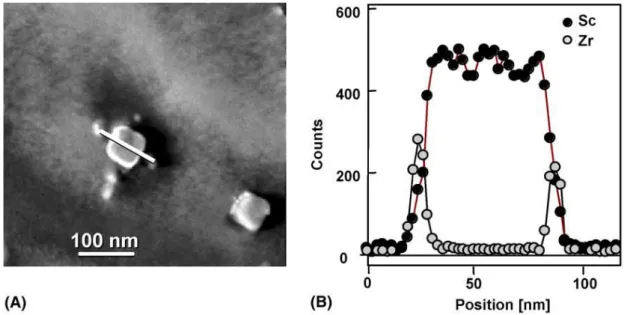
to the segregation of Zr element around Al3Sc cores as shown in Fig. 2.17 [56]. Zr element
possessed a slower diffusion rate which slowed down the coarsening rate of Al3(Sc,Zr)
precipitates. Because of the excellent thermal coarsening resistance of Al3(Sc,Zr) precipitates,
Al3(Sc,Zr) precipitates may be a great choice to be introduced into AA3xxx alloys for further
enhancing the elevated temperature properties. In the previous studies, none of the study is found about the effect of Sc and Zr on AA3xxx alloys.
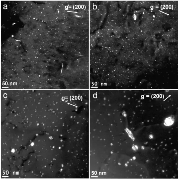
Fig. 2.16 TEM dark-field images showing the Al3(Sc,Zr) precipitates in an Al-B4C composite:
(a) initial peak aging (350 ◦C/10 h), (b) 2000 h annealing at 300 ◦C, (c) 1000 h annealing at 350 ◦C and (d) 2000 h annealing at 350 ◦C.
Fig. 2. 17 (a) Dark field image of a precipitate in ternary Al–Sc–Zr. The image was obtained close to the 001 zone axis. (b) Composition profile along the line indicated in (A) showing the number of EDS counts under the Sc Kα and Zr Kα peaks as a function of position
2.4 Mechanical properties at elevated temperature
2.4.1 Strengthening mechanisms for yield strength at elevated temperature
The yield strength of materials measured at elevated temperature is a very important property to evaluate the performance of materials for elevated-temperature applications. The yield strength contribution at elevated temperature could be divided into following three parts: aluminum matrix contribution, secondary precipitation particles strengthening contribution and solid solution strengthening contribution. According to previous literature, the yield strength of commercial pure aluminum alloys AA1100-O at 315°C is 14 MPa [57]. The precipitation of secondary strengthening phases can effectively slow down the movement of dislocations even at elevated temperature. However, the strengthening mechanism depends on the size of strengthening phases. According to literature[58], while the size of strengthening phase is less than ~8nm, the strengthening mechanism is dislocation climbing mechanism at 300 °C. On the other hand, Orowan bypass strengthening mechanism is the dominant strengthening
mechanism when the size is larger than 8nm. The theoretical calculation of yield stresses based on the model of dislocation climb and Orowan mechanisms is shown in Fig. 2.18.
Fig. 2.18 Theoretical calculation of yield stresses based on the models of dislocation climb and Orowan mechanisms for an Al-B4C composite with 0.24 vol.% Al3Sc at 300°C as a function
of precipitate radius.
2.4.1.1 Orowan strengthening mechanism
For the large size strengthening phases, Orowan proposed a mechanism illustrated in Fig. 2.19 [59]. The yield stress is determined by the shear stress required to bow a dislocation line between two particles separated by a distance L. Stage (a) shows a straight dislocation line approaching two particles. Stage (b) the line is beginning to bend. At stage (c), since the segments of dislocation that meet on the other side of the particles are of opposite sign, they can annihilate each other, leaving a dislocation loop around each particles [60]. Finally, at stage (e), the dislocations are free to move on.
The yield strength contribution of large size particles could be calculated according the following equation [61]:
∆σOrowan = 0.4MGmbln(2rb) π√1−vmλ Eq. 2.12 λ = [(3π 4f) 1 2-1.64]r Eq. 2.13
Where M was Talor factor; Gm was shear modulus of Al matrix; b was Burgers vector, v was
Poison ratio; λ was interspacing of dispersoids; r was average radius of dispersoids; f was volume fraction of dispersoids.
Fig. 2.19 A dislocation bypasses impenetrable particles, shown schematically. The external stress increases from left to right
2.4.1.2 Climb strengthening mechanism
According to Fig. 2.18, while the size of strengthening phases is smaller than 8 nm, at elevated temperature dislocations overcome obstacles by climbing mechanism [58]. For dislocation climb to occur, the diffusion of vacancies is very important. When a vacancy arrives at the place where the dislocation is stuck, it can help the dislocation climb out of its glide plane as shown in Fig. 2.20 [62]. Due to importance of diffusion rate for climbing, climbing is highly dependent on the temperature. At higher temperatures dislocations are more easily to move around obstacles. For this reason, many hardened materials become exponentially weaker at higher temperatures. The repulse stress for dislocation climbing is caused by the elastic
interaction between the dislocations and the precipitates [63]. The components of the elastic reaction are due to lattice mismatch and modulus mismatch [62]. Therefore, the dislocation climbing mechanism (σClimb) consisted two parts: modulus mismatch strengthening (σMMC) and lattice mismatch strengthening (σLMC). The equations were as following:
∆σClimb = ∆σMMC+∆σLMC Eq. 2.14 ∆σMMC = MF 3 2 (Gmb22π3f ) 1 2 br Eq. 2.15 ∆σLMC = χM(εGm)32√2fbr Gmb2 Eq. 2.16
Where, χ=2.6 [58, 64] was a constant, ε [58, 65]was the constrained strain, Gm=21.1GPa [58]
was shear modulus of Al matrix, M=3.06 [58] was mean matrix orientation factor, b=0.288nm [58] was Burgers vector, r was average radius of precipitates, f was volume fraction of precipitates, F [58] was force on the dislocations.
Fig. 2.20 Geometry of general climb model, showing an edge dislocation with segment CD in the glide plane and segment AC climbing over a particle
2.4.1.3 Solid solution strengthening mechanism
When solute atoms are introduced, local stress fields are formed that interact with those of the dislocations, slow their motion and causing an increase in the yield stress of the material, which means an increase in strength of the material. This is the solid solution strengthening [66]. There are two types of solid solutions as shown in Fig. 2.21. If the solute and solvent atoms are roughly similar in size, the solute atoms will occupy lattice points in the crystal lattice of the solvent atoms. This is called substitutional solid solution. If the solute atoms are much smaller than the solvent atoms, they occupy interstitial positions in the solvent lattice. This is called interstitial solid solution [67]. The strengthening contribution of the solid solution of solute elements could be calculated according to the equation below [27, 28]:
σSS =HCα Eq. 2.17
Where C was concentration of solute atoms, H and α are constant.
Fig. 2.21 Schematic models of solid solutions: substitutional solid solution and interstitial solid solution [68]
2.4.2 Creep phenomenon and mechanisms at elevated temperature
2.4.2.1 Creep phenomenon
Creep is a permanent deformation of materials under constant load and at constant temperature. It can occur as a result of long-term exposure to high levels of stress that are still below the yield strength of the material [69].
Generally, there are three different regions of tensile creep as shown in Fig. 2.22. The strain rate of the primary creep region is very high due to the material elastically and plastically responds to the applied load. While the deformation keeps increasing, the material is strengthened by work hardening, which leads to the decrease of the creep rate. As the deformation continues, primary creep stage gradually transits into the secondary creep stage. This stage is also called the steady-state creep. The creep rate almost does not change with time under a constant load. This is a result of the balance between recovery and hardening. The secondary creep region dominates most of the time of the test. Therefore, the secondary creep rate is one of the most important design parameters derived from the creep curve for the design of components. As creep continuing, the secondary creep changes into the third stage (tertiary creep).Tertiary creep only occurs in tensile creep test. Continuous deformation produces voids or internal cracks which decrease the cross-section and increase the stress. As a result, a neck occurs at tertiary stage of the creep, which ends up the fracture of the materials (Fig. 2.22). The tertiary stage creep possesses a much higher creep rate.
However, in compression creep curves, there is no such necking as occurred in tensile creep tests, due to the geometric effect that the sample cross-section will get larger with increased strain. Thus, the steady-state creep stage dominated during compression creep. As shown in Fig. 2.22 (dotted lines), the compressive creep curves can be generally divided into two different stages, and no tertiary creep can be observed.
Fig. 2.22 Typical creep curve showing the three steps of creep [70]. The dotted line shown in the figure is for the compression creep curves
2.4.2.2 Creep mechanism
Creep mechanism is highly dependent on the applied temperature and stress. Weertman Ashby[71] plots creep deformation mechanism map according to the temperature and stress as shown in Fig. 2.23. The creep mechanism is categorized into four types: dislocation glide creep, dislocation creep, Coble creep, Nabarro-Herring creep.