HAL Id: hal-03036472
https://hal.archives-ouvertes.fr/hal-03036472
Submitted on 2 Dec 2020
HAL is a multi-disciplinary open access
archive for the deposit and dissemination of
sci-entific research documents, whether they are
pub-lished or not. The documents may come from
teaching and research institutions in France or
abroad, or from public or private research centers.
L’archive ouverte pluridisciplinaire HAL, est
destinée au dépôt et à la diffusion de documents
scientifiques de niveau recherche, publiés ou non,
émanant des établissements d’enseignement et de
recherche français ou étrangers, des laboratoires
publics ou privés.
A robust inverse analysis method for elastoplastic
behavior identification using the true geometry
modeling of Berkovich indenter
César Moisés Sánchez Camargo, Anis Hor, Catherine Mabru
To cite this version:
César Moisés Sánchez Camargo, Anis Hor, Catherine Mabru.
A robust inverse analysis
method for elastoplastic behavior identification using the true geometry modeling of Berkovich
indenter.
International Journal of Mechanical Sciences, Elsevier, 2020, 171, pp.105370.
an author's
https://oatao.univ-toulouse.fr/26942
https://doi.org/10.1016/j.ijmecsci.2019.105370
Sánchez Camargo, César Moisés and Hor, Anis and Mabru, Catherine A robust inverse analysis method for
elastoplastic behavior identification using the true geometry modeling of Berkovich indenter. (2020) International
Journal of Mechanical Sciences, 171. 105370. ISSN 0020-7403
A
robust
inverse
analysis
method
for
elastoplastic
behavior
identification
using
the
true
geometry
modeling
of
Berkovich
indenter
Cesar-Moises
Sanchez-Camargo
∗,
Anis
Hor
,
Catherine
Mabru
Institut Clément Ader (ICA), Université de Toulouse, CNRS, ISAE-SUPAERO, UPS, INSA, Mines-Albi, 3 rue Caroline Aigle, 31400 Toulouse, France
Keywords: Nanoindentation Finite element modeling Inverse analysis Friction effect
a
b
s
t
r
a
c
t
Theparametersdescribingtheelastoplasticbehaviorofthe316Lausteniticstainlesssteelareidentifiedthrough inverseanalysisbasedonfiniteelementmodelingoftheBerkovichnanoindentationtest.Thetruegeometryof theBerkovichindenterisintroducedinaxisymmetricand3Dfiniteelementmodelsusingexperimental nanoin-dentationdataobtainedbyadaptingthecalibrationmethodproposedbyOliverandPharr[1].Then,usingthese trueindentershapemodels,theelastoplasticparametersofthe316Lareestimatedwithhighaccuracycompared totheparametersobtainedfromtensiletestidentification.Theindentationcurvewascorrectlydescribedbythe numericalmodelforalltheanalyzedindentationdepths,evenforindentationsinferiorto100nm,whichisa challengeuntiltoday.The3Dindentermodelproducesaresidualimprintveryclosetotheexperimental indenta-tionmark.Thefrictionanalysisbetweentheindenterandthesamplesurfacerevealssmallchangesinthesurface deformation,introducinganincreaseonthehardness,whichdisappearsastheindentationdepthdecreases. Thesestudiesdemonstratethatthemostimportantaspectintheelastoplasticparameteridentificationisthe correctrepresentationoftheindentergeometryinthefiniteelementmodel.
1. Introduction
Indentationisapopularmethodforevaluatingelastic-plastic prop-ertiesofmaterialsandstructures,includingelasticmodulus,hardness andyieldstrength[2,3].Severalresearchstudieshaveusedthistestto analyzework-hardening,residualstress[4],andfracturetoughness[5], etc.,thesepropertiesareimplicitlyrelatedwithindentationresponse. Thislocalizedtestcanalsobeappliedtomeasurethepropertiesof indi-vidualphasesaswellasglobalpropertiesofcompositematerials, coat-ingsandmultilayers[6,7].Sinceitrequiresmuchlesseffortonsample preparationthanothertechniques, itis inparticularusefulforsmall materialstructuresandbiologicalmaterials(includinglivingtissues). Duetotheinvolvedfinitelocaldeformationandnonlinearcontact con-ditions,numericalmodelingofindentationisavaluabletoolto under-standofthelinkbetweenindentationdataandmaterialproperties,and tocorrelatetheindentationresultswithmaterialparameters.Then,an inverseanalysiscanbecarriedouttoidentifythesematerialproperties fromindentationtests.
Theelastoplasticcharacterizationofmetalsbynanoindentationtest remainsoneofthebiggestchallengesinthemicro-characterization do-main[8,9,10].Themethodsofelastoplasticcharacterizationby nanoin-dentationtestcanprovideaccesstothemechanicalbehavior[11]at multiplescalesandinconditionswheretheconventional methodsof mechanicalcharacterization(e.g.tensiletest)aredifficultor
impossi-∗Correspondingauthor.
E-mailaddress:[email protected](C.-M.Sanchez-Camargo).
bletoapply,e.g.multi-layerssystems,functionalizedsurfacesamong others.Theadvantageoftheuseofthenanoindentationtechniqueis thatitisabletomechanicallytestvolumesofmatterinthemicroscale, producingexperimentaldataofhighaccuracy.
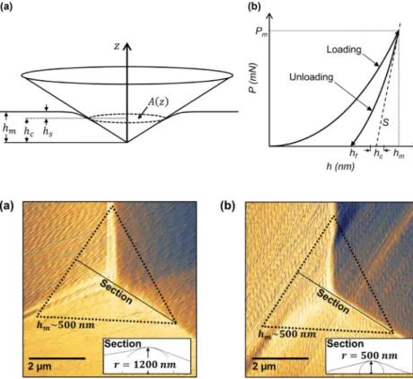
Thenanoindentationtestproducestwomainpiecesofinformation: theresidualimprintandtheloading-unloadingcurve(referredalsoas nanoindentationcurve).Theparametersdescribingtheresidualimprint andthenanoindentationcurveare:hmisthemaximumdisplacementof theindentermeasuredfromthefreesurface,hcisthedepthtothe
con-tactpoint;hsisthedistancefromthecontactpointtothefreesurface,
A(z)isthecrosssectionareaoftheindenteratthecontactpoint,Pmis
thepeakindentationload,Sistheslopeoftheunloadingbranchofthe nanoindentationcurve,andhfisthelastpointofcontactbetweenthe
indenterandthetestedsurface.
Actually,severalmethodsofestimationoftheelasticmodulusand thehardnessofthetestedsurfaceareavailable[12,13].Thesemethods purelyelasticarebasedonlyontheunloadingstageofthe nanoinden-tationtest(Fig.1)[14].Inthecaseoftheelastoplasticcharacterization, twomaintypesofapproacheshavebeendevelopedsincetheapparition of thenanoindentationtest:theanalyticalinversemethods[9,10,11] andthenumericalinverseanalysis[8,15].
Ingeneralterms,theanalyticalmethodsarebasedonthe hypoth-esisofarepresentativestrainassociatedwiththegeometryofthe in-denter[16],i.e.thestraininducedinthesurfaceisindependentofthe
Fig.1. (a)Schemaoftheindentation,and(b)typical corre-spondingnanoindentationcurve.
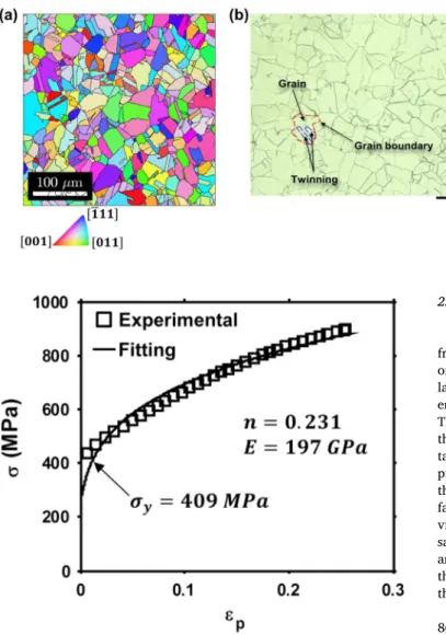
Fig.2. AtomicForceMicroscopy(AFM)capturesofBerkovich indenters:(a)wornindenterwithtipradiusof1200nmand (b)newindenterwithtipradiusof500nm.
indentationdepth.Usingadimensionalanalysis[17],andfiniteelement modeling,a vastamount of workshas beenpublished, forinstance, amongthemostrelevant,thosepresentedin[18,19,20,21,22,47–50]. Suchmethodsarebasedonfiniteelementsimulationsofawiderange ofelastoplasticparameterstodeterminethecoefficientsofthe dimen-sionlessfunctions.These methodsweredevelopedusingthe microin-dentationonarangeof1<hm≤20𝜇m,where,accordingtothe
au-thors,thedefectsanddeviationsontheindentercanbeneglected.In thenanoindentationscale,i.e.0<hm≤200nm[23,24],thewearand thedeviationsontheindentertiparenotnegligible.Theeffectsofthese deviationsonindentershapeareconfirmedbyDaoetal.[19],where theyobservedinfiniteelementsimulationsthatavariationof2° onthe halfangleofaconicalindenterresultsin15−20%variationsinthe
P−hloadingcurvature.
Since, in nanoindentation,the effectsof thewearand deviations onthetipmustbetakenintoaccountonfiniteelementsimulationsa methodtoreproducethephysicalindentergeometryinthefinite ele-mentmodelisrequired.Ingeneraltwoapproachesrelatedtothis is-suecanbefoundintheliterature:i)themodelingoftheindenterasa sphero-conicalrevolutionshape[25,26,27,28,29]andii)themodeling oftheindenterfromacloudofpointsgathered withanatomicforce microscope[30,31].Aremarkableexampleofthefirstapproachwas proposedbyPelletieretal.[25].Theprincipleofthismethodconsists inthedescriptionoftheBerkovichindenterbasedontheuseofthe func-tionareaproposedbyOliveretal.[1],whichrelatesthecrosssection areaof theindenter tothedistancemeasuredfromitstip.Fromthis functionareaanequivalentfunctionareadescribingasphero-conical indenterisderived.Thelimitationofthisapproachisthattheindenter issphero-conical; thereforetheresidualimprintcannotbe compared withtheexperimentalresidualimprintofaBerkovichindenter.
Themostrelevantworkfoundforthesecondapproachwasproposed byKrieretal.[30].TheauthorscapturedtheBerkovichindenter ge-ometrywithanAtomicForceMicroscopy(AFM) andthenintroduce thetruegeometryin thefiniteelementmodel. Theirmethodis able toreproducequitewell indentationsdowntohm =40nm.However theimplementationofthemethodisachallengeforseveralreasons,in particularthecorrectionoftheAFMcloudofpoints.Inthisworkthe
authorsstatedthatthebluntingtipdefectaffectstheload-displacement curve,especiallytheloadingphase,andalsotheelastic–plasticstress andstrainfieldsbeneaththeindenter.Theyhighlightedthatthiseffect ontheelastic–plasticstrainfieldisarealandphysicaleffectthat can-notbeavoidedandlimitedbyananalyticalmodel[30].Thisstatement isverifiedthroughAFMcapturesofthetwoBerkovichindenters avail-ableforthepresentresearch(Fig.2),whichexhibitdeviationsonthe selectedoperativerange.Butalsotheartefactsthatmustbecorrected ifthecaptureisusedtoreproducetheindentergeometryinthefinite elementmodelarevisible.
Althoughthestudiescitedaboveaddresstheproblematicassociated withthedescriptionofthephysicalBerkovichindenter,itdoesnotexist, accordingtoourpresentknowledge,areliableandeffectivemethod tointroducethetrueindentergeometryon thefiniteelement model allowingthecorrectrepresentationofindentationsonstrainhardening solidsintheinterval0<hm≤500nm.Theobjectiveofthispaperisto
providesuchmethodandevaluatethefollowingaspects:
1 Theabilityoftheproposedmethodtocorrectlydescribetheshapeof theBerkovichindenterinbothaxisymmetricand3Dfiniteelement models.
2 Theaccuracyoftheelastoplasticparametersidentificationusingthe inverseanalysisbasedonthefiniteelementmodelincludingthetrue indentergeometry.
3 Numericaleffectsofthefrictionanditsroleinthenanoindentation simulation.
2. Experimental study
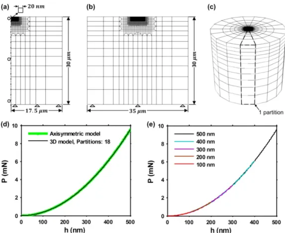
Thematerialusedinthisresearchisthesingle-phaseaustenitic stain-lesssteelAISI316L[32].Themicrostructureiscomposedofequiaxed grainswithamultitudeoftwinning(Fig.3a).Thegrainsizeisbetween 10and40𝜇m.Thecrystallographicstructureofthisausteniticphaseis Face-CenteredCubic(FCC).Theelectronbackscatterdiffraction(EBSD) mapshowninFig.3bhighlightsanon-texturedmaterial.
Themechanicalbehaviorofthe316Lwascharacterizedbyuniaxial tensiletest[33].TheYoung’smodulusobtainedwiththistensiletestis
Fig.3. (a)Microstructureand(b)textureof316Lstainless steel.
Fig.4. Truestress-truestraincurveof316Lstainlesssteel.
method(Fig.4),accordingtotheconstitutiveequation[19]:
𝝈 =𝝈𝒚 ( 1+ 𝑬 𝝈𝒚𝜺𝒑 )𝒏 (1)
where𝝈yrepresentstheyieldstressandnthehardeningexponent.The
valuesofyieldstressandhardeningexponentidentifiedfromthe ten-siletest,usinganoffsetof0.2%plasticstrain,wereconsideredasthe referencevaluesoftheelastoplasticparametersandwereusedasa com-parisoninthefollowingtoassesstheaccuracyoftheanalysisproposed inthispaper:𝝈y=409MPa andn=0.231
2.1. Surfaceoptimizationfornanoindentationexperiments
Ananoindentationspecimenwasmachinedinacubeof2cmside fromthe316Lsameroundbarstockthatwasusedfortensiletest.In order toensureasurfacerepresentativeofthebulkmaterial, thetop layerofthemachinedsurfacewasremovedgraduallyfollowingthis it-erativeprocedure:firstly,theinitialheightofthesamplewasmeasured. Then,mechanicalgrindingusingSiCpaperswasdownto1200gritand thefinalheighthasbeenre-determinedagain.Then,five nanoinden-tationsusingPm =50mNwereconducted.Finally,theheightof the pile-upfromAFMcapturesoftheresidualimprintwasestimated.Once thepropertiesmeasured(i.e.hmandpile-up)becameconsistent,the
sur-facewaspolishedusingadiamondsolutionof1𝜇m,andfinishedwith vibratorypolishingusingcolloidalsilicaduringeighthourswithonly sampleweight[34].Thevariationsinthemeasuresofhm (Fig.5(a))
andtheheightofthepile-up(Fig.5(b))duringtheprocedurerevealed thatthemachiningprocessinducedagradientofproperties,extending througha250𝜇mlayerfromthefreesurfaceofthesample.
Themeanvalueofhmwas 820nmonthestabilized surface,and
860nmonthepolishedsurface(Fig.6(a)).Theresidualimprintonthe polished surfacerevealedthe influenceof the crystallographic char-acteristics of theindented point in theform of asymmetric pile-ups (Fig.6(b)).
The prepared surface was inspected by X-ray diffraction using sin2𝜓 method to analyze the residual stress state [35], finding 𝜎11 = 12∓8MPa and 𝜎22 = −15∓11MPa. The surface can thus
be considered as free from internal stresses. The microstructural-crystallographiccharacteristicsweredeterminedthroughEBSD analy-sis.ThetreatmentoftheEBSDdata[36]revealedadistortionless mi-crostructurefreeofpre-hardening,withanintragranularmisorientation rangingfrom0° to4° atthecenterofthegrains(Fig.7(a)).Theroughness oftheworkingsurfacewasestimatedfromAFMcaptures(Fig.7(b));it wasgloballyRa=4nmandlocallyRa=1.4nm.ThelocalvalueofRa wasusedtodefinetheminimumvalidvalueofhmonthissurface,which
Fig.5. Surfaceoptimizationprocedure:(a)evolutionofhm
and(b)evolutionoftheheightofthepile-upasafunctionof theremovedlayer(affectedbymachining).
Fig.6. Effectsofpolishing:(a)evolutionofhmand(b)residual
imprintofthepolishedsurface.
Fig.7. Surface stateof the polishedsurface:(a) crystallo-graphicmisorientationstateand(b)roughnessstate.
Table1
Finalsurfaceproperties. Roughness
Crystallographic misorientation
(pre-hardening) Residual stresses Ra = 4 nm less than 5° 𝜎11 ≈ 0 MPa/ 𝜎22 ≈ 0 MPa
isofabout28nm,i.e.20timesRa[24].Thepropertiesofthesurfaceat
theendofthepreparationprocedurearelistedinTable1.
2.2. Nanoindentationexperiments
Oncetheworkingsurfacewasprepared,thenanoindentation exper-imentswereoptimizedandconductedonthepolishedsurface.Allthe nanoindentationexperimentswereconductedusingthewornBerkovich indenteroftipradiusr=1200nm(Fig.2(a))inloadcontrolledmode atroomtemperatureonaNHT2commercialnanoindenterfromAnton Paarinstruments.Theoptimumloading/unloadingratewasdetermined experimentally on the optimized working surface. Series of nanoin-dentationexperimentswereconductedusingaconstantloadingforce
Pm=10mNandvaryingtheloadingrate.Thetotalindentationwork
(Wt,Eq.(11))constantuntilavalueofloadingratenearto25mN/min,
afterthisvalue,Wtincreaselinearly(Fig.8(a)).Thereforewe consid-eredthatusingloadingrateslowerthan25mN/minallowsneglecting thetimedependenteffects(e.g.indentationcreep)forPm=10mN.
Onthesmallerscale,thetimedependenteffectscanbeobservedin thefirststageoftheloadingnanoindentationcurve(Pmbetween0and
0.5mN),whereloadingratesgreaterthan6mN/minintroduceaslight increaseintheloadingcurve(Fig.8(b)).Finallyusingtheloadingrate closeto6mN/minallowsobtainingcomparableindentationcurvesfor differentindentationloadingvalues.Thevaluesofloading/unloading rateusedinthisstudy(Table2)wereselectedrespectingthisrule,and consideringtheacquisitionfrequencytohavesimilarquantity experi-mentalpoints(i.e.usinglowerloadingratesforthesmallerPm).
Basedon thisinformation,theexperimentalprotocolwasdefined (Table2).ThistablealsopresentsthehmproducedbytheselectedPm.
Table2
Experimentalprotocolforindentationtestsusingthe wornBerkovichindenter.
Pm ( mN ) hm ( nm ) Loading / unloading rate ( mN / min )
0.3 25 0.5
1 68 1
3 150 3
10 330 6
15 420 6
Themaximumhmisinferiorto500nm,asrequiredforthepresentstudy,
andtheminimumhmisgreaterthan20nm,whichisvalidwithrespect
tothelocalroughnessoftheworkingsurface(Fig.7(b)).
Atotalofninenanoindentationswereappliedforeachofthefive peakloadslistedintheTable2,spacedenoughtoavoidinterferences. Accordingtotheliterature[24],theindentationmustbespacedatleast threetimesthediameteroftheimprintmark.Inthisstudyweuseda spacingoftentimesthediameteroftheresidualimprint.Fromeach groupofnineindentationstheP−hcurvessharingthesameloading pathwereselected(Fig.9(a)),andanAFMcaptureoftheirrespective residualimprintswastaken(Fig.9(b)).
3. Numerical method
3.1. Finiteelementmodelingofthespecimen
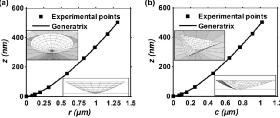
Allthesimulationsinthispaperwereconductedincontrolled dis-placementappliedtotheindenter.Thespecimenwasmodeled asan axisymmetricbodyandasafull3Dmodel[37]usingtheimplicit non-lineargeometryFEalgorithminAbaqus[38].
Firstly,theaxisymmetricmodelwasoptimizedthroughamesh re-finement convergence analysis, using a fixed hm = 500nm, a rigid
cone equivalent to a perfect Berkovich indenter [39], a frictionless contact,andtheelastoplasticparametersoftheEq.(1):E=180GPa,
𝜎y =148MPa, n=0.278[40].Theiterativeprocedurewasapplied
Fig.8. Analysisofnanoindentationtimedependenteffectson 316L:(a)effectsofloadingrateonWtand(b)effectsofloading
rateonthefirstportionoftheloadingnanoindentationcurve.
Fig. 9. Nanoindentation experiments using the worn Berkovichindenter:(a)P−hcurvesand(b)residualimprints associatedtoeachP−hcurve.
Oncetheoptimummeshandsizeofthespecimenwasfoundforthe axisymmetricmodel(Fig.10(a)),thecharacteristicsoftheaxisymmetric modelwerereplicatedonthe3Dmodel(Fig.10(b)).Then,themesh densityofthe3Dmodelwasincreasedbyaddingpartitions(Fig.10(c)), untiltheloadingcurvesofthe3Dandtheaxisymmetricmodelswere equivalents(Fig.10(d)).
Finallybothmodelswereparametrized,usingasmasterparameter
hm:thereforethesamemodelwassuitablefor theanalysisofalarge rangeofhm,ensuringsimilarcontactconditions(Fig.10(e)).
3.2. Finiteelementmodelingoftheindenter
Theproposed methodis basedontheuseofseveralvaluesofthe sectionareaAoftheindenterandtheircorrespondingvaluesofz,i.e.
A(z),withztheneutralaxisoftheindenter(Fig.11).ThevaluesofAare usedtodefinethepointsofthegeneratrixatthecorrespondingzvalues. Then,thegeneratrixisrotatedaroundthezaxisfollowingacircular directrixtoobtainaconicalindenter(Fig.11(a)).Inthecaseofa3D indenter,thegeneratrixismovedalongastraightdirectrixtogenerate onewalloftheindenter.Then,usingacircularpatterntheotherthree wallsaregeneratedandtrimmedontheintersections(Fig.11(b)).The stepsrequiredtoobtainthegeneratrixforbothindentersareexplained below.
Forsimplicity,theexplanationofthemethodisbasedonthe assump-tionofaperfectBerkovichindenter(Fig.11).Consideringtheareaofthe circularsectionofacone,theassociatedradiusisgivenbytheequation:
𝐫(𝐳)= √
𝐀(𝐳)
𝝅 (2)
wherer(z)isthegeneratrixintheaxisymmetricfiniteelementmodel (Fig.11(a)).
Movingtothe3Dindenter,thesectionoftheindenterhasashape ofanequilateraltriangle(Fig.11(b)).Thelengthof eachsideofthe
triangleisgivenbytheequation:
𝑎(𝑧)= √
𝐴(𝑧)√4 3
(3)
Then,theperpendiculardistancefromtheaxisoftheindentertothe sideofthetriangleiscomputedfrom:
𝑐(𝑧)= 𝑎(𝑧) 2 tan
(
30◦) (4)
Inthiscasec(z)isthegeneratrixofthewall,anda(z)isthe direc-trix.Introducingtheindenteronthefiniteelementmodelrequiresthe valuesofAalongtheaxiszoftheindenter.Awell-knownrelationisthe BerkovichfunctionareaA(z)=24.5z2[1].Usingthisrelationonthe
proposedprocedureaperfectBerkovichindenterisgenerated,whichis characterizedbyanangle𝜃 =70.3° inthecaseofanaxisymmetric in-denter(Fig.11(a)),orbyanangle𝛼 =65.3° inthecaseofa3Dindenter (Fig.11(b)).
Sincetheobjectiveis tointroducethetrue indentergeometryon thefiniteelementmodel,itisrequiredtoestimateAatseveralpoints ofthezaxisofthephysicalindenter.Thisproblemwassolvedafew decadesagobyOliverandPharr[1].Theprincipleofthismethodisto estimateAatagivencontactdepth,hc,throughtheindentationona
well-knownmaterial(Fig.1).Ontheirworktheyproposedtousethe fusedquartzasindentedmaterialwiththeelasticconstantsEs=72GPa
and𝜈s=0.17;andadiamondBerkovichindenterwiththeelastic
con-stantsEi=1141GPaand𝜈i=0.07.
Firstly,Aiscalculatedusingtherelation:
𝑆= 𝑑𝑃 𝑑ℎ = 2 √ 𝜋𝐸𝑟 √ 𝐴 (5)
whereSisthecontactstiffness,computedattheinitialportionofthe unloadingdata(Fig.1),andthereducedmodulus,Er,iscomputedusing
Fig.10. Nanoindentationfiniteelementmodeling:(a)axisymmetricmodel(b)sectionofthe3Dmodel(c)partitioningofthe3Dmodel,(d)equivalencebetween the3Dandtheaxisymmetricmodeland(e)loadingcurvesproducedbytheparametrizedmodelsonawiderangeofhm.
Table3
Experimentalprotocolforindentationsonfusedquartz. Indentation numbers Peak load (mN)
Loading/unloading rate (mN/min) Oliver and Pharr [1] 1–10 0.1 0.6 11–20 0.3 1.8 21–30 1 6 31–40 3 18 41–50 10 60 51–60 20 120 Extension 61–70 40 240 71–80 60 360 81–90 80 480 therelation: 1 𝐸𝑟 =1−𝜈𝑠 2 𝐸𝑠 +1−𝜈𝑖 2 𝐸𝑖 (6) where𝜈sandEsaretheelasticconstantsforthespecimen,and𝜈iandEi
arethesameparametersfortheindenter. Then,hciscomputedfromtheequation:
ℎ𝑐=ℎ𝑚−ℎ𝑠 (7)
wherehsisthedeflectionofthesurfaceoutsidethecontactarea(Fig.1),
whichiscomputedfromtheequation:
ℎ𝑠=𝜋2(𝜋 −2)𝑃𝑆𝑚 (8)
Onthisstudy,themethodofOliverandPharr[1]wasusedunder threeconsiderations:1)hcis equivalenttoz,2) theoriginal
nanoin-dentationprotocolusedonthefusedquartz(Table3),wasextendedto estimatethevalueofAforacorrespondingvalueofz=500nm,and
3)theelasticconstantsoftheBerkovichindenterandthefusedquartz werethesamethatthoseproposedbyOliverandPharr[1];both,the di-amondBerkovichindenterandthestandardizedsampleoffusedquartz wereobtainedfromthemanufactureroftheNHT2nanoindenter.The indentersgeneratedwiththeproposedprocedurearereferredastrue indenters.
Finally,9valuesofA(z)werecomputedusingtheextendedmethod ofOliverandPhar[1]indentingonfusedquartz(Fig.12),tocovera maximumz=500nm.
ThephysicalBerkovichindenterwasintroducedinthefiniteelement modelapplyingthisprocedurethroughPythonscriptsinAbaqus,in sep-aratemodelsintheformofaxisymmetric(Fig.13(a))and3D(Fig.13(b)) indenters,respectively.TheexperimentalpointsA(z)weredirectlyused togeneratetheindentergeometriesaddinganinitialpointintheorigin. Nofittingprocedurewasincludedtocreatethegeneratrixofthe inden-ters.Theaxisymmetricmodel(Fig.13(a)),ispresentedintheformof aconeusingthevisualizationcapabilitiesofAbaqus.The3Dindenter (Fig.13(b)),isafull3DrepresentationofthephysicalBerkovichused intheexperiments.
Oncethecharacteristicsofthespecimenandtheprocedureto gen-eratetheindenterwereestablished,thenextstepistodefinethe inter-actionbehaviorbetweenthesurfacesoftheindenterandthespecimen.
3.3. Indenter-specimencontactmodeling
Theinteractionbetweentheindenterandthespecimenwasdefined inAbaqusStandardusingthemaster-slaveconfiguration[38].The mas-tersurfacewastheexternalsurfaceoftheindenter,andtheslavesurface wastheexternaltopsurfaceofthespecimen.Theinteractionbetween theindenterandthespecimenwasanalyzedintwoways:1)in friction-lesscontact,and2)withfrictioncontact.Thefrictionwasintroduced in the modelusing the formulationof Coulombincludedin Abaqus
Fig.11. Geometricspecificationsoftheindenters:(a)conical indenterand(b)3Dindenter.
Fig.12. Experimentalpointsobtainedfromindentationonfusedquartzusing thewornBerkovichindenter.
[38]. Thisformulationassumesthatthere isnorelativemovementif theequivalentfrictionalstressgivenby
𝜏𝑒𝑞= √ 𝜏2 1+𝜏 2 2 (9)
isinferiortothecriticalstress,𝜏crit,whichisproportionaltothecontact
pressure,p,intheform:
𝜏𝑐𝑟𝑖𝑡=𝜇𝑝 (10)
Thefrictioncoefficient,𝜇,isafunctionofthecontactpressure,p, thesliprate,theaveragetemperature,andtheaveragefieldvariables atthecontactpoint.If𝜏crit=𝜏eq,slipoccurs.Inthisstudythefrictionis
consideredisotropic.Thedirectionoftheslipandthefrictionalstressis coincident.
3.4. Optimizationprocedureforelastoplasticparametersidentification
TheLevenberg-Marquardt[41]optimizationalgorithmwasusedto determinetheelastoplasticbehaviorparameters.Theobjectivefunction proposedisformulatedusingbothloadingandunloadingbranchesof theP−hcurve(Fig.1).
Fromtheloadingcurvethetotalindentationwork,Wt,isobtained
withtheexpression:
𝑊𝑡= ℎ𝑚 ∫
0 𝑃𝑑ℎ
(11) whichisusedtodefinethefirstcomponentoftheobjectivefunctionin theform:
𝑓𝑡=𝑊𝑡𝑛
−𝑊𝑡𝑒
𝑊𝑡𝑒 (12)
whereWtn isthetotalindentationworkobtainedfromthesimulated
loadingcurve,andWteisthetotalindentationworkobtainedfromthe experimentalloadingcurve.
Usingtheunloadingcurve,theelasticindentationwork,We,is
ob-tainedthrough: 𝑊𝑒= ℎ𝑚 ∫ ℎ𝑓𝑃𝑑ℎ (13)
whichisusedtodefinethesecondcomponentoftheobjectivefunction intheform:
𝑓𝑒=𝑊𝑒𝑛
−𝑊𝑒𝑒
𝑊𝑒𝑒 (14)
whereWenistheelasticindentationworkobtainedfromthesimulated
unloadingcurve,andWeeistheelasticindentationworkobtainedfrom theexperimentalunloadingcurve.
UsingtheEqs.(12)and(14),theobjectivefunctionforthewhole
P−hcurveisassembledintheform:
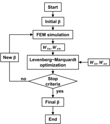
𝑓(𝛽) 𝑚𝑖𝑛= [ 𝑓𝑡 𝑓𝑒 ] (15) where𝛽 representsthesetofelastoplasticparameters.Finally,the mini-mizationoftheobjectivefunctionisachievedusingthealgorithmshown intheFig.14.
Thealgorithmusedinthisworkwassetwithasteptoleranceand functiontoleranceof10−14.Changesinresidualswassetwithavalue
of10−6,andthenumberofiterationswassetasinfinite.
Fig.13. Berkovichindentermodeling:(a)generatrixofthe axisymmetricindenterand(b)generatrixofthe3Dindenter.
Fig.14. Optimizationalgorithmusedfortheelastoplasticparameter estima-tion.
4. Results and discussion
4.1. Thetrueindentergeometrymodelling
Fortheinvestigatedindenter height,i.e. 0nm<z ≤500nm,the profileofthetrueaxisymmetricindenter(Fig.15(a)),looksmorelike aparabola thana sphero-conicalindenterasstatedbysomeauthors [25,26,27,28,29].Infact,theprofileofthetrueindenterneverexhibits aparallelismwithrespect totheperfectindenter(70.3°).Thisfound helpstoexplainwhythepolynomialformofthefunctionareausedby OliverandPharr[1]isabletodescribetheBerkovichindenterwithhigh precisionregardlessaphysicalmeaning.Anothermethodtodetermine thefunctionarea,includingaphysicalmeaning,wasproposedby Lou-betetal.[42].Thismethodreliesontheestimationoftheheightofa roundedportion(thetipdefect),connectedtoaperfectindenter.The3D indentermodeledwiththemethodproposedinthispapercannotbe
de-scribedusingthisassumption,becausethesectionsofthetrueindenter arecurved(Fig.15(b)).
Inaddition,thecloudofpointsgatheredbytheAtomicForce Mi-croscopy(AFM) wasdirectly used forcomparisons, founding thatat leastoneofthethreesectionsobtainedfromtheAFMcaptureofthe Berkovichtipispartiallysimilartothesectionofthetrueindenter, ex-hibitingarelationwiththephysicalindenter.
4.2. Elastoplasticparametersidentification
Thethreeelastoplasticparametersofthe316Lconstitutivemodel described in Eq. (1) were estimated from each experimental P − h
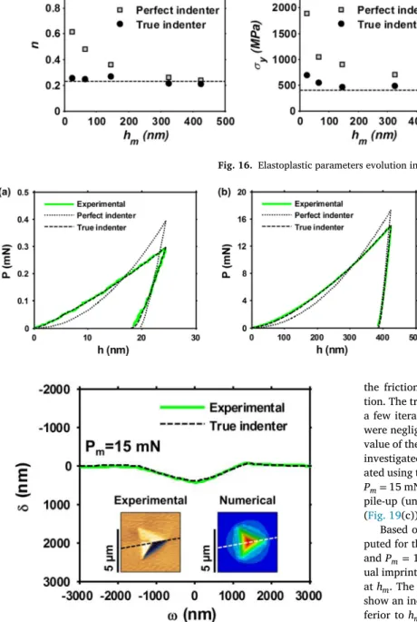
curveobtainedwiththeindentationsusingthewornBerkovich inden-ter(Fig.9(a))andtheparameteridentificationroutine(Fig.14).Both perfectandtrueindentermodelswereusedintheaxisymmetricmodels, assumingfrictionlesscontact(𝜇 =0inEq.(10)).Theestimated param-eterswereplottedasafunctionofthemaximumindentationdepthin Fig.16,andthevaluesoftheparametersobtainedbytensiletestwere includedasreference.
Thethreeelastoplasticparametersobtainedwiththe perfect inden- ter model increasewithrespecttothereference(tensile)valuewhen
hmdecreases.Fortheminimumvalueofhm,theerrorinthehardening
exponentreaches%err=166i.e.n=0.61,whichisoutoftherangefor
metals[19];theerrorintheyieldstressreaches%err=370andisalso
outoftheparametricrangeofmetals[19].
However,theelasticmodulusandthehardeningexponentestimated with the true indenter model exhibitaconstanttrendnearthe refer-ence. Thehardeningexponentandtheelasticmodulus havea mean error%err=3.7and%err=17.8respectivelycomparedtothereference.
Theerrorintheyieldstressonthemaximumvalueofhmis%err=21.6.
This errorincreaseswiththedecreaseof hmtoreach%err=72.9.In theliterature,theincrease oftheyieldstrengthwiththedecreaseof
hm,reflectedonthehardness,isreferredasindentationsizeeffect(ISE) [43,44,45].WesupposethattheISEisalreadypresentinthemaximum
hminvestigated,andthatiswhythevalueoftheelasticlimitisgreater
thanthevaluefoundbytensiletest.Thisfindingopenthepossibilities tonewexperimental-numericalstudiesoftheISE,besidestheexisting formulationsbasedonthehardnesse.g.themethodofGaoetal.[44].
Inaddition,theparameter identificationconductedwiththe per-fectindentermodelwasclosetotheknown(reference)solutionforthe indentationcorrespondingtothegreaterhm.Thiseffectcanbeeasily observedintheP−hcurves,wherethesimulationoftheshallow in-dentationexhibitsagreatdifferencewithrespecttotheexperimental curve(Fig.17(a)),whileinthedeepestindentationthedifference be-tweenthemisreduced(Fig.17(b)). Nevertheless,theparameter esti-mationperformedusingthetrueindentergeometryshowedpowerful
Fig.16. Elastoplasticparametersevolutioninfunctionofhm.
Fig.17. Comparisonbetweenthetrueindenterandthe per-fectindenterP−hcurvesin(a)shallowand(b)deep inden-tations.
Fig.18. Comparisonbetweentheexperimentalresidualimprintprofileandthe numericalresidualimprintprofileobtainedwiththe3Dmodel.
capabilitiesofthismodeltofaithfullyreproducetheexperimentalcurve fordeepandshallowindentations(Fig.17(a)and(b)).
Finally,thesectionoftheresidualimprintproducedbythe3Dtrue indentermodelwithPm=15mN,fortherespectivedetermined
elasto-plasticparameters, isvery closeatleast tooneof thethreesections obtainedexperimentally(Fig.18).Thisgreatresemblancealsoconfirms thattheoptimizationroutineconvergedtothecorrectsolutioninthis case.
4.3. Frictionanalysis
Theparameteridentificationroutinewasexecutedtwotimes sepa-ratelyusingthefrictioncoefficients𝜇 =0.1and𝜇 =0.2respectively, foreachinvestigatedexperimentalindentationonthe316L.The start-ingpointoftheroutinewasthelastsetofparametersdeterminedwith
thefrictionlessconfiguration of eachparameter identification execu-tion.Thetrueindenterfiniteelementmodelwasused.Inallcases,after afewiterationstheroutinestoppedbecausethechangesinthecurve werenegligible(Fig.19(a)and(b)),inconsequencethechangesinthe valueoftheparameterswerealsonegligible.Therefore,theeffectofthe investigatedfrictioncoefficients(𝜇 =0; 𝜇 =0.1; 𝜇 =0.2)were evalu-atedusingthedeterminedelastoplasticparametersfortheexperimental
Pm=15mN.Theresidualimprintshowedadecreaseoftheheightofthe pile-up(until31nmfor𝜇 =0.2),comparedtothefrictionlesscontact (Fig.19(c)),revealingsmallvariationsinthecontactarea.
Basedonthisevidence,thehardness,H=Pm/A(hc)[1],was com-putedfortheexperimentalP−hcurveswithPm=3mN, Pm=10mN
andPm=15mNusingtheAFMcapturesoftheircorresponding
resid-ualimprints.Inthecaseofthenumericalmodels,A(hc)wasdetermined athm.Theresultswereplottedinfunctionofhm(Fig.20).Theresults
showanincreaseofHwiththedecreaseofhm.Fortheindentations
in-feriortohm=200nm,theeffectsofthefrictionarereduced,i.e.the
changesinthecontactareaarenegligible.Forindentationssuperiorto
hm=200nm,theexperimentalHisclosetothesimulationusing
fric-tionlesscontact,andtheincreasewhen𝜇 = 0.2induces%err=19.6,
meaningadifferenceofHabout490MPa.
Theliteraturereportsamaximumincreaseof ~ 20%inthe hard-nessforcontactswithfrictioncoefficients𝜇 >0[46].Themaximum differencefoundinthiswork(%err=19.6)isconsistentwiththese ob-servations.However,forthedeeperindentationsanalyzedinthiswork, thevaluesofthehardnessobtainedusingfrictionlesscontactarecloser totheexperimentalvalues.
Mataetal.[46]observedtwoeffectsofthefrictiononthepile-up: 1)theheightofthepile-updecreaseswiththeincreaseofthefriction coefficient,and2)theindentationswithlowheightofpile-upareless sensitivetothevariationsofthefrictioncoefficient.Thetwoeffects ob-servedbyMataetal.arepresentedinthisstudy(Fig.21).Thefirstone isobservedwithindentationsofhm>300nm,whereamaximum
dif-ferenceof27.8nmontheheightofthepile-upisobservedcomparing frictionlesscontactandcontactwithfrictioncoefficient𝜇 =0.2.The secondeffectisobservedwithindentationsofhm<100nm,wherethe
Fig.19. Frictioneffects:(a)inshallowand(b)indeepindentation,ontheP−hcurves,(c)ontheresidualimprint.
Fig.20. Frictioncoefficienteffectonthesurfacehardness.
Fig.21. Effectsofthevariationsofthefrictioncoefficientonthepile-upheight.
5. Conclusion
Anewmethodologytoimprovetherepresentationofthegeometryof thephysicalBerkovichindenterinthefiniteelementmodelisproposed inthispaper.
Thisinclusionofthephysicalindenterinthefiniteelementmodel leadstoacorrectreproduction oftheexperimentalP− hcurveand
residualimprintofthetestedmaterial,providinganestimationofthe elastoplasticparameterswithsignificantlyimprovedaccuracyinthe op-erative range0<hm≤500nm. Theobservedvariationsoftheyield
stressasafunctionoftheindentationdepthopennewinsightsonthe indentationsizeeffect,which nowcanbe analyzedthrough sophisti-catednumericalmodelsonindentationswithhm<100nm.Thispaper
focusedontheanalysisofstrainhardeningsolids,howevercomplex mi-cromechanicalsystems(e.g.ultrathinlayers,nanocrystallinestructures, etc.) canbe analyzedusingtheaccuratefiniteelementmodelof the indentergeometry.
Theeffectsofthefrictioncoefficientwereobservedinthecontact interface betweentheindenter andthesamplesurfacemodifyingthe valueofthehardness,whichis ingoodagreementwithotherworks reportedintheliterature.Noeffectsofthefrictioncoefficientusedin thefiniteelementsimulationswereobservedontheP−hcurveoron theestimatedparameters.
Declaration of Competing Interest
None.
Acknowledgments
This workwaspartiallysupportedbytheMexicanCouncilof Sci-enceandTechnology(CONACYT).TheassistanceofDr.VictorSanchez inthereviewofthismanuscriptisgratefullyacknowledged.Wewishto acknowledgetheassistanceofMr.ThierryMartinfortheoptimum per-formanceofthenanoindenter,andthesupportofalltheISAE-SUPAERO DMSMteam.
References
[1] Oliver WC , Pharr GM . An improved technique for determining hardness and elastic modulus using load and displacement sensing indentation experiments. J Mater Res 1992;7:1564–83 .
[2] Iracheta O , Bennett C , Sun W . Characterization of material property variation across an inertia friction welded CrMoV steel component using the inverse analysis of nanoindentation data. Int J Mech Sci 2016;107:253–63 .
[3] Ben Ismail A , Rachik M , Mazeran P-E , Fafard M , Hug E . Material characterization of blanked parts in the vicinity of the cut edge using nanoindentation technique and inverse analysis. Int J Mech Sci 2009;51:899–906 .
[4] Zhu L , Xu B , Wang H , Wang C . Measurement of residual stress in quenched 1045 steel by the nanoindentation method. Mater Charact 2010;61(12):1359–62 .
[5] Romana L , Thomas P , Bilas P , Mansot JL , Aldana Aranda D . Use of nanoindentation technique for a better understanding of the fracture toughness of Strombus gigas conch shell. Mater Charact 2013;76:55–68 .
[6] Lai D , Xu J , Xie Z , Habibi D , Munroe P . Mechanical characterization of a novel nanocrystalline coating: first-principles calculations and nanoindentation. Mater Charact 2012;68:1–6 .
[7] Bouzakis K-D , Michailidis N , Hadjiyiannis S , Skordaris G , Erkens G . The effect of specimen roughness and indenter tip geometry on the determination accu- racy of thin hard coatings stress–strain laws by nanoindentation. Mater Charact 2002;49(2):149–56 .
[8] Kang J , Becker A , Sun W . Determining elastic–plastic properties from indentation data obtained from finite element simulations and experimental results. Int J Mech Sci 2012;62:34–46 .
[9] Kim M , Pandian Marimuthu K , Lee JH , Lee H . Spherical indentation method to eval- uate material properties of high-strength materials. Int J Mech Sci 2016;106:117–27 .
[10] Nguyen N-V , Kim JJ , Kim S-E . Methodology to extract constitutive equation at a strain rate level from indentation curves. Int J Mech Sci 2019;152:363–77 .
[11] Pham T-H , Kim JJ , Kim S-E . Estimating constitutive equation of structural steel using indentation. Int J Mech Sci 2015;90:151–61 .
[12] Oliver WC , Pharr GM . An improved technique for determining hardness and elastic modulus using load and displacement sensing indentation experiments. J Mater Res 1992;7(6):1564–83 .
[13] Oliver WC , Pharr GM . Measurement of hardness and elastic modulus by instru- mented indentation: advances in understanding and refinements to methodology. J Mater Res 2004;587(1):3–20 .
[14] Bulychev S , Alekhin V , Shorshorov MK , Ternovskii A . Mechanical properties of ma- terials studied from kinetic diagrams of load versus depth of impression during mi- croimpression. Strength Mater 1976;8(9):1084–9 .
[15] Kang JJ , Becker AA , Wen W , Sun W . Extracting elastic-plastic properties from ex- perimental loading-unloading indentation curves using different optimization tech- niques. Int J Mech Sci 2018;144:102–9 .
[16] Tabor D . The hardness of solids. Review of Physics in Technology 1970;1(3):1–145 .
[17] Barenblatt GI . Scaling, self-similarity, and intermediate asymptotics: dimensional analysis and intermediate asymptotics. Cambridge University Press; 1996 .
[18] Cheng Y-T , Cheng C-M . Scaling approach to conical indentation in elastic-plastic solids with work hardening. J Appl Phys 1998;84(3):1284–91 .
[19] Dao M , v Chollacoop N , Van Vliet KJ , Venkatesh TA , Suresh S . Computational mod- eling of the forward and reverse problems in instrumented sharp indentation. Acta Mater 2001;49:3899–918 .
[20] Bucaille J-L , Stauss S , Felder E , Michler J . Determination of plastic properties of metals by instrumented indentation using different sharp indenters. Acta Mater 2003;51:1663–78 .
[21] Chollacoop N , Dao M , Suresh S . Depth-sensing instrumented indentation with dual sharp indenters. Acta Mater 2003;51(13):3713–29 .
[22] Ogasawara N , Chiba N , Chen X . Measuring the plastic properties of bulk materials by single indentation test. Scr Mater 2006;54:65–70 .
[23] ISO 14577-1:2015. Metallic materials - Instrumented indentation test for hardness and materials parameters, part 1: test method. Switzerland: Geneve; 2002 .
[24] Fischer-Cripps AC . Nanoindentation testing. Springer; 2011. p. 21–37 .
[25] Pelletier H , Krier J , Cornet A , Mille P . Limits of using bilinear stress–strain curve for finite element modeling of nanoindentation response on bulk materials. Thin Solid Films 2000;379:147–55 .
[26] Bouzakis K-D , Pappa M , Maliaris G , Michailidis N . Fast determination of parameters describing manufacturing imperfections and operation wear of nanoindenter tips. Surf Coat Technol 2013;215:218–23 .
[27] Berla LA , Allen AM , Han SM , Nix WD . A physically based model for indenter tip shape calibration for nanoindentatio. J Mater Res 2010;25(4):735–45 .
[28] Yu N , Polycarpou AA , Conry TF . Tip-radius effect in finite element model- ing of sub-50 nm shallow nanoindentation. Thin Solid Films 2004;450(2):295– 303 .
[29] Chen W , Li M , Zhang T , Cheng Y-T , Cheng C-M . Influence of indenter tip roundness on hardness behavior in nanoindentation. Mater Sci Eng 2007;445:323–7 .
[30] Krier J , Breuils J , Jacomine L , Pelletier H . Introduction of the real tip defect of Berkovich indenter to reproduce with FEM nanoindentation test at shallow penetra- tion depth. J Mater Res 2012;27(1):28–38 .
[31] Herrmann K , Hasche K , Pohlenz F , Seemann R . Characterisation of the geome- try of indenters used for the micro-and nanoindentation method. Measurement 2001;29(3):201–7 .
[32] Sapezanskaia I , Roa JJ , Fargas G , Turon-Viñas M , Mateo A . Deformation mecha- nisms induced by nanoindentation tests on a metastable austenitic stainless steel: a FIB/SIM investigation. Mater Charact 2017;131:253–60 .
[33] Davis JR . Tensile testing. ASM International; 2004 .
[34] Wang Z , Bei H , George EP , Pharr GM . Influences of surface preparation on nanoin- dentation pop-in in single-crystal Mo. Scr Mater 2011;65(6):469–72 .
[35] Basrour S , Robert L . X-ray characterization of residual stresses in electroplated nickel. Mater Sci Eng 2000;288(2):270–4 .
[36] Bachmann F , Hielscher R , Schaeben H . Texture analysis with MTEX - free and open source software toolbox. Solid State Phenom 2010;160:63–8 .
[37] Larsson P-L . Investigation of sharp contact at rigid-plastic conditions. Int J Mech Sci 2001;43:895–920 .
[38] M. Smith, ABAQUS/Standard User’s Manual, Version 6.9, Simulia, 2009. [39] Bolshakov A , Pharr GM . Influences of pileup on the measurement of mechan-
ical properties by load and depth sensing indentation techniques. J Mater Res 1998;13:1049–58 .
[40] Beghini M , Bertini L , Fontanari V . Evaluation of the stress-strain curve of metallic materials by spherical indentation. Int J Solids Struct 2006;43:2441–59 .
[41] Marquardt DW . An algorithm for least-squares estimation of nonlinear parameters. J Soc Ind Appl Math 1963;11(2):431–41 .
[42] Loubet JL , Georges JM , Marchesini O , Meille G . Vickers indentation curves of mag- nesium oxide (MgO). J Tribol 1984;106:43–8 .
[43] Swadener J , George E , Pharr G . The correlation of the indentation size effect mea- sured with indenters of various shapes. J Mech Phys Solids 2002;50(4):681–94 .
[44] Nix WD , Gao H . Indentation size effects in crystalline materials: a law for strain gradient plasticity. J Mech Phys Solids 1998;46:411–25 .
[45] Shim S , Bei H , George EP , Pharr GM . A different type of indentation size effect. Scr Mater 2008;59(10):1095–8 .
[46] Mata M , Alcala J . The role of friction on sharp indentation. J Mech Phys Solids 2004;52(1):145–65 .
[47] Cao YP , Lu J . A new method to extract the plastic properties of metal materials from an instrumented spherical indentation loading curve. Acta Mater 2004;52:4023–32 .
[48] Casals O , Alcalá J . The duality in mechanical property extractions from Vickers and Berkovich instrumented indentation experiments. Acta Mater 2005;53:3545–61 .
[49] Gao X-L , Jing XN , Subhash G . Two new expanding cavity models for inden- tation deformations of elastic strain-hardening materials. Int J Solids Struct 2006;43:2193–208 .
[50] Giannakopoulos AE , Suresh S . Determination of elastoplastic properties by instru- mented sharp indentation. Scr Mater 1999;40:1191–8 .