To cite this document: Lizy-Destrez, Stéphanie and Ferraioli, Giuseppe and
Audas, Chloé and Piat, Jason How to save delta-V and time for a round trip to
EML2 Lagrangian point? (2012) In: IAC 2012, 01-05 Oct 2012, Naples, Italie.
O
pen
A
rchive
T
oulouse
A
rchive
O
uverte (
OATAO
)
OATAO is an open access repository that collects the work of Toulouse researchers and
makes it freely available over the web where possible.
This is an author-deposited version published in:
http://oatao.univ-toulouse.fr/
Eprints ID: 6619
Any correspondence concerning this service should be sent to the repository
administrator:
[email protected]
!
HOW TO SAVE DELTA-V AND TIME FOR A ROUND TRIP TO EML2 LAGRANGIAN POINT?
Stéphanie Lizy-Destrez,
ISAE/SUPAERO, France, [email protected]
Giuseppe Ferraioli, ISAE/SUPAERO, France, [email protected]
Jason Piat, ISAE/SUPAERO, France, [email protected]
Chloé Audas, ISAE/SUPAERO, France, [email protected]
Space exploration follows a logical set of steps, starting with basic knowledge and culminating, hopefully, in a sustained human presence in space. The next step, according to the Global Exploration Roadmap, released in September 2011 by the International Space Exploration Coordination Group (ISECG), which reflects the international effort to define feasible and sustainable exploration pathways to the Moon, near-Earth asteroids and Mars, is the Moon as second home in the Solar System.
On the basis of risk, cost and technology readiness criteria, the present paper aims to provide quantitative results to set up a Deep Space-Habitat, as an exploration gateway, at the Earth Moon Lagrange point n°2 (EML2), on the way to the Moon, Mars and asteroids colonization. Highly reliable and safe systems are crucial as interplanetary resupply missions from Earth cannot reach the crew at short notice and a quick return to Earth is not possible. This problem is the strong link with the last year’s article “Mission analysis for a space medical center of an exploration gateway at a lunar libration point”, published at IAC in Cape Town, in 2011. Here a further analysis will be carried out on how to develop the preliminary bibliographical studies and to go deeper into the modeling of scenarios.
In a first analysis, a local optimization of the deployment of the Deep-Space Habitat for an international space heaven located at EML2 is performed. After investigating different propulsion technologies, a general analysis in order to minimize the cost to join the permanent outpost in the Earth-Moon system is run. The future needs an exploration gateway at a lunar libration point which will be developed for a 2035 timeframe, as indicated by the Global Exploration Strategy, might slightly change. As a direct consequence, the number of modules composing the Deep-Space Habitat is not specified to make the analysis more generic and flexible.
Secondly, special emphasis is placed on locally optimizing the operational phase, with the mission analysis of the resupply cargo. The time to come back to Earth is the dimensioning parameter in order to guarantee safety in emergency cases for the crew.
Finally, a global optimization for the entire Deep-Space Habitat mission, encompassing deployment and operational phase can be started. I. INTRODUCTION
Human and robotic exploration of the Moon, asteroids, and Mars will strengthen and enrich humanity’s future, bringing nations together for a common cause, revealing new knowledge, inspiring people, and stimulating technical and commercial innovation [1]. These are the substantial benefits delivered to society.
The Global Exploration Strategy [2] also identified the common goals, among all the nations, for space exploration:
- search for life;
- extend human presence;
- develop exploration technologies and capabilities; - perform science to support human exploration; - stimulate economic expansion;
- perform space, Earth and applied science; - engage the public in exploration;
- enhance the Earth’s safety.
Space agencies participating in ISECG have defined a long-range human exploration strategy that begins with the International Space Station and expands human presence throughout the Solar System, leading to human missions to explore the surface of Mars.
Human exploration preparatory activities are needed in order to achieve the ultimate goal (human Mars mission): the Moon will be the first place where humans learn to live on another celestial body. This intermediate step to long range missions is strongly recommended, firstly for financial aspects reasons and then to validate technical solutions. Just three days away from Earth, the Moon’s natural resources and low gravity make it an ideal location to prepare people and machines to venture further into space. As a remnant of four billion years of Solar System history and as a place to observe the Earth and the Universe, it has great scientific potential. Exploration of the Moon will also reveal whether the resources available in space will allow humans to live off the land [2].
In perfect agreement with the Global Exploration Roadmap, the present paper aims to provide quantitative results to establish a Deep Space-Habitat, as an exploration gateway, at EML2, on the way to the Moon colonization. The following paragraph provides an analysis of Lagrangian points as an alternative to go beyond Low Earth Orbit (LEO). The choice of EML2 will also be reasoned. In paragraph III, a preliminary architecture of the expected space station, named Trans-lunar Human explORation (THOR) is described along with the human challenges which lead to its design. Paragraph IV deals with the mission analysis and the problem of optimizing the deployment phase of the resupply cargo for the afore-mentioned Deep Space-Habitat in
EML2. Finally, future perspectives and recommendations are discussed (paragraph V).
II. STRATEGIC CONSIDERATIONS FOR A DEEP SPACE-HABITAT IN EML2
The aim of this paragraph is to show why a crewed space station at the Lagrangian point EML2 provides an environment that is most suitable for almost every research objective, from microgravity to planetary exploration.
The LEO and Geostationary Orbit (GEO) environments are inhospitable for many research objectives because of the long-term threat of space debris [3]. Moreover, LEO has to deal with continuously increasing cargo and passenger traffic [3] along with the problem of materials’ degradation i.e. the plasma environment in LEO is rich in reactive free radicals, particularly atomic oxygen [3].
On the basis of a public and private engagement, proposed by [4], human presence in LEO could still be justified along with an alternative scenario, considering Earth-Moon Lagrangian points, for a permanent human presence in space in the long term.
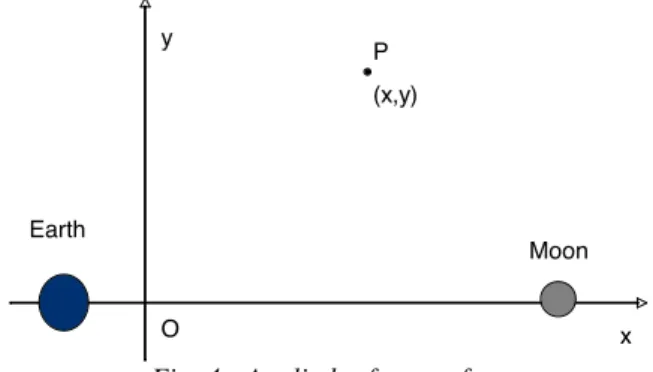
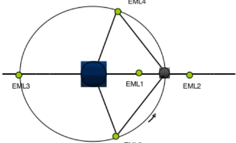
The Lagrangian points are the equilibrium solutions of the Restricted Three Body Problem (RTBP) which describes the motion of a particle, of very small mass, under the gravitational attraction of two massive bodies (usually called primaries, or primary and secondary). It is assumed that the particles are in circular (Keplerian) motion around their common centre of mass. For space missions, the particle is the spaceship and the two primaries can be taken, for example, as the Sun and the Earth-Moon barycenter, or the Earth and the Moon. Since Euler and Lagrange, some relevant solutions of both the General Three Body Problem and the Restricted Circular Three-Body Problem (RCTBP) are known. The latter deals with two massive bodies moving in circular orbits around their common center of mass and the third mass being small and moving in the same plane. For one of the afore-mentioned solutions, the three bodies are on the edges of an equilateral triangle, with the centre of mass at the origin that can rotate with an angular velocity that depends on the masses of the bodies and the size of the side of the triangle. Three of the five Lagrangian points lie on the line joining both primaries: one, usually denoted by L1 (EML1), is between the primaries, and the other two at both sides of the two primaries, the one closest to the smaller primary is called L2 (EML2) and the third one L3 (EML3). The two remaining equilibrium points, L4 (EML4) and L5 (EML5), are in the plane of motion of the primaries and they form an equilateral triangle with the two primaries. This is illustrated in the following figure 1:
Fig. 1: The five libration points in the Earth-Moon system
There are several advantages to these Lagrangian points, such as easy access from both the Earth and the Moon with minimum launch window constraints, no artificial debris hazard, small fuel requirements for station-keeping and a location independent from country borders on Earth. Finally, the decision matrix presented in [5], based on criteria such as crew access from Earth, deployment and resupply efficiency, access to lunar
location, communications station keeping, exploration
capabilities, long term strategy risk and human factor (it will be the first time for a crew to test life behind the Moon, without a permanent visual contact with the planet Earth) justifies the choice of EML2 as a space outpost where to set a Deep Space-Habitat.
III. DESCRIPTION OF THE SPACE STATION This paragraph begins with a brief presentation of some requirements applied to the overall layout and arrangement of the Trans-lunar Human explORation (THOR) Space station. Then, the second sub-paragraph presents a solution for the arrangement of the modules forming the THOR space station. It is here assumed that the space station is composed of seven modules.
III. I Overall Architectural requirements
Habitability includes all qualities that medically and psychologically support a crew’s stay aboard a space station, both at work and during leisure. At the lowest level, the degree of habitability is determined by direct environmental factors - such as temperature, humidity, illumination, noise level and food quantity and quality. All these factors influence the well-being of the crew particularly by supporting physiological functions. With increasing duration of a mission, the influence a stay in an isolated and limited room has on the crew, grows drastically. Habitability is now additionally determined by the maintenance of the crew’s health and psychological balance. It can be improved by an optimal utilization of all available space aboard a space station [6]. This section provides a brief overview of architectural requirements that will be needed to design the THOR space station: general, orientation and visual requirements.
General adjacencies design requirements
Design of any system or facility in the THOR space station should be based on the logical sequence and smooth flow of activities that are to occur in the facility. Generally the most efficient layout is to place compartments adjacent to each other when they are used sequentially or in close coordination. Some crew compartments require a high volume of entering and exiting traffic. Placement of these stations adjacent to each other could result in traffic congestion and loss of efficiency.
Compartments shall be placed adjacent to each other when any of the following conditions exists: sequential dependency, high
transition dependency, shared support equipment.
Compartments shall not be located adjacent to each other when any of the following conditions exist: physical interference, environmental interference (lighting, noise, vibration, heat), EML4
EML2 EML1
EML3
degradation of crew health and safety, infringement on privacy, infringement on security [7].
Orientation design requirements
Humans, having been raised in a 1-G environment, are accustomed to forming a mental image of their environment with a consistent orientation. People locate themselves and objects according to this mental image. If the person is viewing the environment in an unusual orientation, this mental image is not held. This can provoke disorientation, space sickness, temporary loss of direction, and decreased overall performance. Visual cues are thus needed to help the crewmember quickly adjust his or her orientation to a more familiar view of the world. These visual cues should define some sort of horizontal or vertical reference plane. As a direct consequence, each module shall have a local vertical (a consistent arrangement of vertical cues within a given visual field) so that the vertical orientation within a specific work station or activity center shall remain consistent [7].
Visual design requirements
The longer the mission duration, the greater the tendency for the crew to feel confined and cramped. This can affect psychological health and crewmember performance. The estimated physical space is not necessarily relative to the physical size of the room. The feeling of spaciousness can be achieved visually through the arrangement, colour, and design of the walls and partitions of the space module. For instance, irregular shaped rooms are perceived to have more volume than compact or regular shaped rooms of equal volume. Brightness, colour saturation, and illumination levels have also an effect on perception of volume. In addition, windows allow the crewmember to focus on objects, such as Earth, outside the space module. This can significantly increase the sense of spaciousness and psychological well-being of the crewmember. Windows also help to support proximity operations, Earth and celestial viewing. For these reasons, they should be located near module workstations, scientific workstation, near recreational and socialization areas, near areas of boring, monotonous tasks (exercise, for instance) and near private quarters [7].
III. II THOR architectural design solution
Previous analysis results [5] show that the THOR space station needs at least seven modules to be built. The modules are cylinders of a 20t mass, 5m diameter and 10m long. In order to provide crewmembers with a feeling of verticality, the seven modules were assembled so that four of them were placed in a horizontal reference plane and three of them in a vertical one. Horizontal and vertical directions are defined, in paragraph IV, according to synodic referential frame in Earth-Moon system and related to the orbital motion around EML2. The station is orientated towards the Earth, so that the three top modules can be qualified as the northern part of the station and the three bottom modules as the southern part. The placement of windows - allowing the Earth observation and consequently orientation towards the same - could help crewmembers to form this mental image. Figure 2 depicts the THOR space station orientation and the way its seven modules have been assembled.
Fig. 2: THOR space station overall design (Blender). In order to avoid traffic congestion spherical modules have been placed at the intersection between the three modules of the northern part and the three of the southern parts. These spherical modules can be compared to a crossroad and would function much the same as hubs. Windows would be added to their top parts to allow celestial viewing.
The functional assignment of the modules shall be established so as to reproduce the terrestrial way of life [8]. As shown in Figure 3, activities are divided into four categories: private, public, group and individual activities. These are assigned a certain set of coordinates. The larger the distance between two activities, the greater their potential incompatibility.
The three first modules in the northern part of the station have been dedicated to private and leisure activities whereas the last three modules in the southern part have been dedicated to public and work activities. This configuration aims to create the psychological impression of travelling from home to work.
Fig. 3. Social classification of different activities [7].
The present paragraph has shown a preliminary architecture of THOR space station. The deployment and operational phase will now be discussed in the following paragraphs.
IV. MISSION ANALYSIS
This paragraph presents the mission analysis for a spaceship for the THOR manned space station in the vicinity of the Earth-Moon Lagrangian point EML2. Such a mission shall go through five main stages, besides the launch: a LEO phasing, a Lunar Transfer Orbit, docking and undocking maneuvers and return to Earth. A prior bibliographical study showed that the most decisive phase would be the Lunar Transfer, as it represents high energy costs i.e. big changes in velocity ∆V and would determine directly the duration of the flight, this last phase being a key in the case of crew transport.
The first sub-paragraph presents an overview of modeling and computing the means for a transfer from a Low Earth Orbit to an orbit around EML2.
Then, the analysis of the transport from Earth’s surface to orbit (sub-paragraph IV.II) is discussed along with the optimization of the deployment phase of the servicing ship for the THOR space station in EML2 (sub-paragraph IV.III).
IV.I Description of the trajectory from Earth proximity to Halo orbit
Transfer strategies
Different transfer strategies can be selected, such as direct Hohmann transfers, weak stability boundary transfers and fly-by trajectories for the transfer stage from Halo orbit to Earth proximity.
Direct Hohmann transfers (classical elliptical transfers) are the shortest and the most costly in terms of ∆V. Typical values found in the bibliography range from 5 to 7 days and from 4.03 to 4.45 km/s [9]. These trajectories are a very simplified way to model the transfer since they cannot render the approach maneuvers that have to be performed at the injection in the targeted orbit around EML2. A more detailed modeling of the transfer is needed if a complete mission analysis is to be performed.
Weak Stability Boundary trajectories are very complex trajectories in which the gravitational pull of the Sun is used to raise the perigee of the transfer orbit to reach the Moon region. The spacecraft is sent to the vicinity of Sun Earth Lagrangian point n°1 (SEL1) before coming back to EML2. This enables a very fuel-efficient yet very long trip, which can last from 90 up to 120 days while consuming 3.2km/s. While unsuitable for manned flights, it could prove very useful for cargo shipping [10], [11].
Finally, fly-by trajectories use the gravitational slingshot effect of the Moon to reduce the ∆V. They can either be direct or indirect. Additionally, after the lunar fly-by, the spaceship can be injected with a maneuver as small as 60m/s into one of the trajectories of a series called the stable manifold of the selected EML2 orbit. The manifold can be described as a group of trajectories that exponentially tend towards the EML2 orbit, forming a tube. As explained later, flying the ship on this manifold means that no additional injection maneuver is needed to reach the space station. A typical total ∆V for such maneuver would be approximately 3.4 km/s, while the trip would last from 15 to 29 days according to the source [12], [13].
The fly-by trajectories are both an accurate and relatively easy way to compute such a transfer from Earth to EML2. The transfer is basically computed backwards. Firstly, a representation of the targeted orbit must be obtained. Then, the stable manifold that leads to this orbit has to be computed, so that a trajectory can be chosen within it, with regard to its lunar fly-by characteristics. Finally, the position and velocity of the lunar fly-by point is used as a final condition to integrate backward the equation of motion and produce an elliptical transfer from the Earth to the manifold. This strategy needs imply the study oftwo dynamic motions: the general keplerian dynamic can be used to compute the elliptical transfer from the Earth to the stable manifold, while the Restricted Circular Three-Body Problem provides us with linearized equations of motion in the vicinity of EML2.
Restricted circular three-body problem
In the RC3BP model, the spaceship is under the gravitational attraction of the Earth and the Moon, which are called the primaries and supposed to be on circular orbits about their common center of mass. In order to simplify the expressions, the masses, distances and time are normalized respectively with the sum of the primaries’ masses, the distance between them and their angular velocity around their barycenter. The equations are written in the synodic frame, centered around the center of mass and with the x-axis directed from the Earth to the Moon and the y-axis in the plane of the primaries’ motion (figure 4).
Fig. 4 : Applied reference frame
Finally, the spaceship is free to move three dimensionally and its mass is supposed not to affect the primaries motion. The equations of the spaceship motion are the following:
!" ! "#$ # %& %! #" ! $"!$ #%& %# ' !%& %' & !!"# $ ! # # $ " # ! % %!% ##%& ( ! &" O y x Earth Moon P (x,y) (2) (5) (3) (4) (1)
where x,y and z are the coordinates of the ship, U is the potential of the system, µ is the mass parameter and m1 and m2, r1 and r2 are respectively the mass and distance from the ship to each primary.
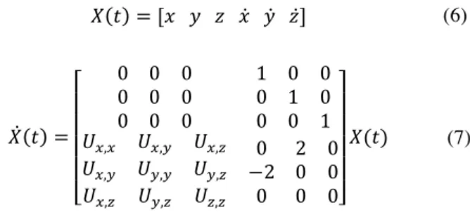
It is then possible to linearize the system around EML2, and by defining the state vector X as follows, we can write:
)*+, ! '! # ' !$ #$ '$( )$*+, ! . / / / / 0 ) ) ) ) ) ) ) ) ) * ) ) ) * ) ) ) *
&(!( &(!) &(!*
&(!) &)!) &)!*
&(!* &)!* &*!*
) " ) $" ) ) ) ) )1 2 2 2 2 3 )%+&
where Ui,j are the derivatives of the potential and the matrix A linking X and its derivative is called the state propagation matrix.
Targeted orbit
Once the problem is linearized, a general solution for the motion of the ship can be found, by studying the specter of matrix A.
! ! 4!+,-56()+7 # 4%+,-5$6()+7 # 4+./058()+7
#4,01258()+7
# ! 9!4!+,-56()+7 $ 9!4%+,-5$6()+7 #
9%4,./058()+7 $ 9%4+01258()+7
' ! 4-./0*8*+, # 4.012*8*+,
The Ai amplitudes are given by the initial conditions and the pulsations λi and ωi can be obtained through a first order linearization around EML2. The family of orbits so defined is called Lissajous orbits when Ax and Az are not equal to zero. The space station is supposed to follow a Halo orbit around EML2, which corresponds to an orbit where ωxy = ωz. Those orbits only exist above a certain amplitude and cannot be described by a low degree linearization, contrary to Lissajous orbits. Still, as the terms ωxy and ωz are not very different in the case of Lissajous orbits, we can assume that the resulting phase difference is not significant if the computation is limited to a few revolutions around EML2, as close as possible to the yz-plan. We will thus use a Lissajous orbit as a first approximation for the targeted Halo orbit, which enables us to remain in the linearized system. As a consequence, the results obtained will only describe the insertion of the ship into the orbit and not the final approach of the station.
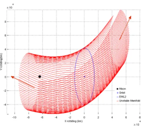
As previously mentioned, Lagrangian points’ orbits are linked to manifolds, which are sets of trajectories that tend towards or outwards a particular orbit. This is a result of the instability of the collinear Lagrangian points and can be described in the previous linearized orbit representation by very small but positive A1 and A2 amplitudes. Each orbit has got two
manifolds, one stable and one unstable. The stable manifold is a series of trajectories that tend toward the orbit from the Moon or from infinity and the unstable manifold is a series of trajectories that lead from the orbit to the two directions. Those properties are very interesting in mission design because if a ship is injected on one of the trajectories of a stable manifold, it joins the associated orbit after a certain duration without any additional manoeuvers. A key point of this work is thus to model and compute the stable manifold resulting from the orbit of the space station.
Computation methods for the manifold
Computation of the manifolds is performed by adding small perturbations to the state vector along the orbit around EML2 and integrating the equations of motion backward or forward. The perturbations have to follow precise directions to lead the ship to escape the orbit on the unstable manifold or to join it by the stable manifold. The more classical method to compute these escape and non-escape directions is to propagate the A matrix along the orbit around EML2 to build the state transition matrix ϕ, also known as the flow of the system.
:$*+3 +/, ! 4%+&:%+3 +/&
ϕ links the state vectors at different times as follows:
)*+, ! :%+3 +/&)%+/&
Finally, the monodromy matrix M is obtained by integrating the state transition matrix over a full period of the orbit, M = ϕ(+/+T,+/). The eigen vectors of M then give the escape and
non-escape directions associated with each point of the orbit. This method is widely used and trustworthy, but the full integration of the monodromy matrix remains very long and demanding in terms of computational power. It is not compatible with the optimization operations that are to be performed in a preliminary mission analysis. A good alternative to this integration has been proposed by the University of Stuttgart [14]. This method relies on a first order linearization of the potential. This way, the state propagation matrix A is constant along the orbit as well as the escape and non-escape directions, which enable the direct integration of the trajectories from all the points of the orbit without needing to compute the monodromy matrix.
Fig. 5 Non escape directions (stable manifold)
(7)
(9)
(10) (6)
Fig. 6 Escape direcions (unstable manifold)
The principles of this method and promising results are featured in [14].
Computation of a complete trajectory
First of all, a very simple Matlab simulator is programmed to calculate the trajectory between the Earth and Manifold, where the Keplerian dynamics apply. It is realized by directly integrating the unlinearized equations of motion with a fixed-step second order Euler integrator.
The next step is the implementation of the algorithm that produces the trajectories of the manifold resulting from the targeted orbit around EML2. This is done by generating a period of a Lissajous orbit using the general solution of the linearized problem and adding small perturbations in the first order escape and non-escape directions. Then a backward integration is performed using the first order state propagation matrix. By improving the first order linearization results suggested by [14], a full representation of the stable manifold coming from the Moon to EML2 was obtained. Nevertheless, some aspects of the model have to be questioned. Further improvements would concern the level of approximation of the algorithm used to join the Lissajous orbit with the manifold.
The last step to compute a complete transfer is to patch the two simulators. The simplest way is to choose a trajectory in the manifold, then a point in this trajectory and use it as a final condition to integrate backward and produce the semi-elliptical transfer from the Earth. Here, an optimization work is needed to select the best trajectory in the manifold along with the most interesting insertion point in order to ensure an efficient fly-by of the Moon. Preliminary results showed that some trajectories in the Manifold could be extended easily to a Height Earth Orbit (HEO). However, the mentioned limits of the manifold computation lead to surprising results concerning the duration of the trip and cost in ∆V. The linearized dynamic model of the manifold is used close or beyond its boundaries due to the amplitude of the orbit and size of the manifold. The next step of this work will thus be a validation of the linearized theory results through a comparison with the classical computation method using the monodromy matrix. A particular attemtion is to be paid to the maximum distance from EML2 where the manifolds trajectories remain valid, as the proximity of EML1 manifolds is problematic in the vicinity of the lunar fly-by.
IV.II Analysis of the transport from Earth’s surface to orbit The previous paragraph has shown the main technical issues for the mission to EML2, dealing with the computation of a complete trajectory.
The following section aims to discuss the problem of the launch, in terms of cost, different orbits in which to inject the spaceship and their effect on the overall optimization process.
Finally, particular emphasis will be placed on the need of a heavy lift launchers fleet for a sustainable mission to EML2. Current launch vehicle systems involve launch costs of the order of 1000 dollars per kilogram of payload delivered. These costs are so high that commercial activities and routine space operations by private companies are not very developed, for the time being [15].
Moreover, tremendous reliability is required since the payloads themselves may be worth millions or billions of dollars.
The cost of a launch is directly linked to the amount of propulsive change in velocity 4;0, the launch vehicle must
provide.
This quantity can be expressed as the sum of three elements, the actual change in velocity 4;1, the change in velocity due to drag
4;2 and the change in velocity due to gravity, 4;3 [16]:
4;0! 4;1# 4;2# 4;3
The actual 4; is the difference between the inertial velocity of the spaceship at rest on a rotating Earth and the inertial velocity of the spaceship at burnout in orbit. As a first order approximation, this can be computed by calculating the orbital velocity ;4$5 and subtracting from it the Earth’s rotational speed
at the latitude of the launch site, typically 5.2° from Kourou(Guyane) [16].
The higher the LEO altitude, the lower the actual 4;.
For the change in velocity due to drag 4;2 (the losses in
velocity due to the inclination effect have been included in this parameter), an average value can be assumed for increasing LEO altitudes.
Finally, the higher the LEO altitude, the stronger the gravity effect [16].
Taking all the afore-mentioned effects into account, where should the orbit injection of the spaceship be performed? LEO altitudes of up to 200km are recommended by [16], the gravity effect being the sizing parameter (gravity losses are very important for high LEO altitudes).
If higher LEO altitudes are to be reached, [16] shows that performing manoeuvers in LEO is less expensive, in terms of the required energy budget, than transporting directly the spaceship to the desired altitude.
Furthermore, the overall optimization process is to be considered, as higher departure orbits imply a lower energy budget for the lunar transfer.
Moreover, an orbit injection at the perigee of a Geostationary Transfer Orbit (GTO) has the same effect on the lunar transfer energy budget than an orbit injection at the corresponding LEO altitude [16].
In order to select the best orbit injection, further studies are to be carried out and propulsion means and costs to reach the departure altitude for the lunar transfer, provided in the previous section, are to be investigated.
In addition, an important corollary of the existence of manned missions is the development of a reliable, low-cost heavy lift vehicle by an international consortium for an international market [3].
A major obstacle to establish an outpost beyond LEO is the lack of an operating launch vehicle to support it.
A heavy lift launcher fleet would save at least half of the cost of current rockets launches [16], the payload being carried to orbit with double the present capabilities.
IV.III Description of the optimization problem
As presented in the last year’s article [5], the THOR space station life-cycle is decomposed into several stages, the main ones being deployement and operations. The deployment stage corresponds to all activities that permit the transfer of all the station elements from Earth to EML2 Halo orbit as well as the integration of the station. The operational phase consists in the space station utilization, during which the crew works at the task at hand.
In our study, two optimization problems emerge:
- For deployment: what is the best strategy to assemble the THOR space station?
- For operations stage: what is the best strategy to resupply the station?
Deployment optimization problem:
Finding the best strategy for deployment means selecting the optimum scenario in which to build the station. It means that we shall determine the optimum set of parameters, when the number of modules is fixed to minimize the total ∆V spent during the entire deployment time range.
A deployment scenario is composed of several stages, namely the launch, orbit in the Earth vicinity, transfer to EML2 neighborhood, rendez-vous and docking.
Selected parameters to model the deployment optimization problem are the altitude of the orbit in Earth Vicinity (LEO, GEO or HEO) and the number of required launches per type of aimed orbit. In actual fact, the first step of the scenario is used to tranport the modules from Earth to space. There are several possibilities: to bring them to LEO, to GEO or to HEO, one by one or together. Of course, the decision depends also on the availability and performances of the launch vehicles. That is the reason why we performed an additional trade-off of which the results are presented in paragraph IV.II.
So as to simplify the optimization problem, in this preliminary analysis, we assume that each of the seven modules has the same mass (equal to 20t) and that each transfer is performed along a manifold.
The approach that we set up, for a given number of modules, consists in determining: firstly the number of potential scenarios, secondly the number of launches per type of aimed orbit so as to compute the ∆V consumed for each stage and the total ∆Vdeployment for the entire deployment phase.
The total ∆V is computed as :
4;67084)&79:! 4;81;9<=# 4;:$19>?7$# 4;$7967*"@4;>
So as to simply the computation, it is supposed that no maneuver is performed during the time spend in orbit around the Earth.
When NLEO represents the number of launches necessary to reach LEO, NGEO the number of launches to reach GEO, NHEO the number of launches to reach HEO and NLaunch the total number of launches, we can write that:
4;81;9<=!<ABC4;0"ABC#<3BC4;0"3BC#<DBC4;0"DBC
<A1;9<=!<ABC#<3BC#<DBC
All
ΔV
p used in the previous formula represent the cost of thelaunch for each orbit type as described in paragraph IV.II. The ∆Vtransfer is computed as described in pargraph IV.I. The ∆Vrendez-vous encompasses cost of maneuvers for approach, rendez-vous and docking. For the moment, it is considered as fixed by comparison with ATV performances. But, some further analyses could improve its computation.
Some data are still parametric, like the number of modules, the altitude of the LEO (varying between 300km and 1000km) or the altitude of HEO. An extension of this study shall be to consider different mass value for the modules.
Operations optimization problem:
Finding the best strategy for operations means determining the scenario that minimizes the total ∆V spent during the operations duration (except for disposal). In this case, we consider only the resupply spaceship transportation. This spaceship can transport crew members or cargo (refueling, food, water, medicines, experiments…).
The set of parameters taken into account for operational phase study is the number of spaceship types (one for crew and cargo, or one for cargo and one for crew), the increment duration (3 months, 6 months, ….) and the last stage (wait in HEO, GEO, LEO for a next re-use or return to Earth).
The expression 4;407$1:E49>shall be:
4;407$1:E49> ! 4;81;9<=# 4;:$19>?7$# 4;$7967*"@4;>
# 4;;964<F# 4;$7:;$9# 4;796
where 4;;964<F is the cost of undocking maneuvers, 4;$7:;$9
the cost of returning to Earth and 4;796 the cost of final
maneuvers when the spaceship is back in the Earth vicinity.
The problem modeling (deployment and operations
optimization) to generate a 3D graphical representation is still in process, so for the time being a decision on the optimum scenario(s) for the building and exploitation of the THOR space station is still pending.
(11)
(12) (13)
V. CONCLUSION
In agreement with the ISECG roadmap, a research team at ISAE/SUPAERO is working on the mission analysis of an inhabited space station, orbiting around the EML2 on a Halo trajectory, so as to provide a safe outpost for human exploration. After a brief description of the Earth-Moon Lagrangian point environment, this article has presented a preliminary functional architecture of the expected space station. Then, a discussion about how to optimize ∆V consumption for deployment and operations phase was proposed.
For those scenarios, the optimization problem was introduced, along with a selection of quantitative parameters and assumptions, for a fixed number of modules (space station basic components) and the methodology to compute ∆V during launch and transfer between Earth and EML2.
Future studies concern the following improvements:
- the space station architecture, taking into account more criteria coming from Human factors lessons learned from ISS missions;
- the trajectories modeling, in particular, the way to transit from one stage to another one (for example from LEO to EML2 transfer on the manifold);
- the development and validation of the optimization problems graphical representation tools.
Even if the future of Human Space Exploration of the Moon, Mars or the asteroids is still uncertain, the research team of
ISAE/SUPAERO will realize the afore-mentioned
improvements with passion and enthusiasm in order to perform space science.
VI. REFERENCES
[1] ISECG, The Global Exploration Roadmap, September 2011.
[2] N.Suzuki, K.Matsumoto, B.Hufenbach, J.Piedboeuf,
W.Cirillo, W.Carey ISECG Space Exploration Goals,
Objectives, And Benefits, IAC-11-A5.4.2 2011.
[!]"Mendell, W. Wendell and S. Hoffman. Considerations for
Cislunar Space Infrastructure. 44th IAF Congress Graz,
Austria. 1993, Paper: IAF-93-Q.5.416.
[4] G.Ferraioli , M. Arbery, N.Bernède, P. Rodríguez Llorca,
L. Faubert, G. Chatelus, , Post-ISS future activities in LEO
(Community of Ariane Cities 2012summer school team project).
[5] S. Lizy-Destrez and C. Blank Mission analysis for a space
medical center of an exploration
gateway at a lunar libration point, IAC-11.A5.5.8, 2011.
[6] E. Messerschmid, R. Bertrand, Space Stations, Systems
and Utilization, Springer, (1999).
[7] NASA, Man-Systems Integration Standards, NASA-STD-3000, Volume I, Revision B (July 1995).
[8] L.M. Jagger, Spacecraft Architectural Design with Minimal
Artificial Weightiness Concept, Cranfield University
College of Aeronautics, ENSICA, (1998).
[9] C. Blank, Mission analysis for the design of the space
medical center of the International Spaceport located at EML1/EML2, 2011 .
[10] E. Belbruno, J. Carrico, Calculation of weak stability
boundary ballistic lunar transfer, AIAA 2000.
[11] F. Garcia, G. Gomez, A note on weak stability
boundaries, Celestial Mechanics and Astronomy 2007 .
[12] F. Renk, M. Hechler, E. Messerschmid, Exploration
Missions in the Sun-Earth-Moon system: A detailed view on selected transfer problems, Acta Astronautica 2009 Vol. 67, pp.
82 - 96.
[13] Mingtao, Li and Jianhua, Zheng. Impulsive lunar Halo
transfers using the stable manifolds and lunar flybys. Acta
Astronautica. 2010, Vol. 66, pp. 1481 – 1492.
[14] F. Renk Mission Analysis for Exploration Missions
utilizing Near-Earth Libration Points. Dissertation, Munich :
Dr. Hut, 2009.
[15] J.Pearson Low cost launch system and orbutal fuel depot, IAF-86-128,1986.
[16] G. Ferraioli Optimization of the deployment phase of the
resupply cargo for an international
space human heaven located at EML2, DMIA, ISAE Toulouse,
![Fig. 3. Social classification of different activities [7].](https://thumb-eu.123doks.com/thumbv2/123doknet/3619666.106296/4.892.496.822.653.951/fig-social-classification-different-activities.webp)