En vue de l'obtention du
DOCTORAT DE L'UNIVERSITÉ DE TOULOUSE
Délivré par :
Institut National Polytechnique de Toulouse (INP Toulouse)
Discipline ou spécialité :
Réseaux, Télécommunications, Systèmes et Architecture
Présentée et soutenue par :
M. MUHAMMAD ADNAN
le jeudi 21 novembre 2013
Titre :
Unité de recherche :
Ecole doctorale :
ANALYSE PIRE CAS EXACT DU RESEAU AFDX
Mathématiques, Informatique, Télécommunications de Toulouse (MITT)
Institut de Recherche en Informatique de Toulouse (I.R.I.T.)
Directeur(s) de Thèse :
M. CHRISTIAN FRABOUL M. JEAN LUC SCHARBARG
Rapporteurs :
M. JEAN-JACQUES LESAGE, ECOLE NORMALE SUPERIEURE DE CACHAN M. THIERRY DIVOUX, UNIVERSITE NANCY 1
Membre(s) du jury :
1 M. GUY JUANOLE, UNIVERSITE TOULOUSE 3, Président
2 M. CHRISTIAN FRABOUL, INP TOULOUSE, Membre
2 M. JEAN-LUC SCHARBARG, INP TOULOUSE, Membre
2 M. JEROME ERMONT, INP TOULOUSE, Membre
2 M. JUAN LOPEZ, AIRBUS FRANCE, Membre
Acknowledgments
With immense pleasure, I acknowledge the help, guidance and support received from various quarters during the course of my PhD studies. Pursuit of PhD degree is a long journey which is very hard to accomplish without the help of others. One of the joys of completion is to look over the journey past and remember all the friends and family who have helped and supported me along this long but fulfilling road. Hence, I hereby express my appreciation to one and all.
My sincere and unbounded gratitude to my advisor Christian Fraboul and co-advisors,
Jean-Luc Scharbarg and Jérôme Ermont for their support and guidance. Their vision and suggestions
throughout the thesis period, from choosing the problem, solving it and its presentation, has been fundamental in completion of the thesis. The joy and enthusiasm they have for the research, was contagious and motivational for me, even during tough times. Sir, you have been a source of motivation throughout. I am also very grateful to the remaining members of my dissertation committee: Professor Guy JUANOLE president of the jury, Jean-Jacques LESAGE and M. Thierry DIVOUX, my honorable reporters, Mme AUGE-BLUM Isabelle and Mr Juan LOPEZ from airbus Toulouse, our industrial partner. Their academic support and input and personal cheering are greatly appreciated. Thank you all.
The members of the research laboratory at ENSEEIHT/IRIT have contributed positively to my personal and professional learning. The team as a whole, has been a source of friendships as well as good advice and collaboration. My colleagues here at ENSEEIHT/IRIT Lab deserve more than a mention. I acknowledge their support and help during my stay in the lab. Their companionship, help and guidance in both academic and logistic issues is worth the praise. The lab wouldn’t be as much fun to stay in without you all. I am grateful to Christelle Jacob and her parents for their hospitality and support on numerous occasions during my stay in France. I felt at home with you all and will cherish these days all my life.
Every one I met at different academic conferences and gatherings, deserves an honorable mention for their discussions and inputs on everything academic or otherwise. I have definitely learned and improved my work with all your suggestions.
My special thanks to all the administrative and secretarial staff, both at the lab and uni-versity and at my embassy and people back home, for doing all the necessary work they did for me, so that I was able to concentrate on my research without distractions.
ii
affection will be treasured throughout. My family members have always been a source of con-stant support, encouragement and inspiration. Thanking them would be an understatement. So I would like to conclude my acknowledgments by dedicating this work to my parents.
Muhammad Adnan University of Toulouse November 2013
Executive Summary (Resume)
Since the last few decades, Information and Communication Technology (ICT) systems are evolving rapidly and they are becoming more and more popular and omnipresent. This trend also exist in aviation domain. Now a days, all modern aircraft have complex suit of on-board electronic devices used for various purposes commonly referred to as Avionics Systems. Avionics systems of an aircraft are used in a wide variety of different applications such as flight control, instrumentation, navigation, communication etc. These avionics systems need to communicate between themselves and exchange data, hence building "Avionics networks". Over the years, demand for data exchange has risen rapidly and avionics networks have evolved from dedicated links to shared buses to switched networks such as Avionics Full-Duplex Switched Ethernet (AFDX). AFDX is a data network for safety critical applications that utilizes dedicated band-width while providing deterministic Quality of Service (QoS). AFDX is based on IEEE 802.3 Ethernet technology and utilizes commercial off-the-shelf (COTS) components. It is described specifically by Part 7 of the ARINC 664 Specification, as a special case of a profiled version of an IEEE 802.3 network per parts 1 & 2, which defines how Commercial Off-the-Shelf networking components will be used for future generation Aircraft Data Networks (ADN). The six pri-mary aspects of AFDX include full duplex, redundancy, deterministic, high speed performance, switched and profiled network. Like any other communication network being used on-board an aircraft, it is very important to know the temporal aspects of data flow on AFDX network, such as communication delay from the source to the destination. These end to end communication delays are important to determine because they are used to certify avionics systems of the air-craft. In this context, the main objective of this thesis is to provide methodologies of finding exact worst case communication delays of AFDX network.
To achieve this goal, different tools and approaches have been analyzed and compared with existing techniques. New approaches and algorithm were also developed during the research work of this thesis. At present two main techniques are being used for end to end delay analysis of AFDX network. These are Network Calculus and Trajectory approach. Both of these are pessimistic in their results and give us a sure upper bound on the end to end communication delays instead of exact values. Network Calculus uses Min Plus algebra for its calculations. The pessimism in results have been reduced by using different techniques such as "grouping". Trajectory approach uses concept of "busy period" to calculate its bounds for end to end commu-nication delays. In some cases Network Calculus has better results than the Trajectory approach while in other cases Trajectory approach gives better results. On average, results of Trajectory approach are tighter than Network Calculus approach and the margin varies depending upon
iv
the VL path.
In order to evaluate exact end to end communication delays, Model checking has been used in the context of AFDX network. Before this research work, it was applied to AFDX network as a proof of concept on a simple configuration. During this work, we have explored Model checking for end to end communication delays of AFDX network in depth, with models reflecting the real configuration parameters, such as asynchronous behavior, packet sizes and BAG values. In this context, existing well established real time model checking tools were explored, such as UPPAAL and NuSMV. UPPAAL suits better for the end to end communication delays in AFDX network as compared to NuSMV because NuSMV can only handle pure discrete models. On the other hand UPPAAL does not have a symbolic representation for the discrete part of the state space and hence it limits the size of models that can be evaluated in reasonable time and computation resources. Still, we were able to evaluate AFDX network of considerably larger sizes than existing approach. We are able to find end to end communication delays of AFDX network with upto 32 VLs.
In order to overcome limitations of Model Checking approach, the work was done in the direction of exhaustive simulation using in house developed algorithms and tools based on these algorithms. The main reason for using this approach was to develop a tool from scratch which is specifically suited for the task of finding exact end to end communication delay of AFDX networks. In order to reduce state space for this exhaustive simulation approach, properties of the AFDX network were exploited and different algorithms were developed which ensure that we only consider cases which can be candidate for worst case end to end communication delays. The end result is encouraging and we were able to analyze large AFDX network configurations. We were also able to analyze part of a real life industrial configuration of the AFDX network with approximately 1000 VLs and 6400 paths. For more than 60% of these paths we were able to find exact end to end communication delays while for the rest we were able to find end to end communication delays which are close to worst case communication delays.
The results obtained from the tool developed during this research were compared with existing approaches. With exact end to end communication delays calculated by this tool, we can find exact pessimism in Network Calculus and Trajectory approaches. On average, Network Calculus is 13% pessimistic in its calculations while Trajectory approach is about 6% pessimistic in its calculations.
Keywords: AFDX Network, Model Checking, Worst Case Communication Delay, Exhaus-tive Simulation
List of Personal Publications
[Adnan 2010b] Muhammad Adnan, Jean-Luc Scharbarg, Jérôme Ermont and Christian Fraboul. Model for worst-case delay analysis of an AFDX network using timed
au-tomata. In Proc. of the 15th ETFA , Bilbao, pp.1-4, 13-16 Septembre 2010. doi:
10.1109/ETFA.2010.5641124 keywords: automata theory;avionics;delays;local area net-works;scheduling;AFDX network;ARINC 664 standard;avionics full duplex switched Ethernet;end-to-end communication delays;local scheduling;timed automata;upper bounds;worst case delay analysis model. URL :http://ieeexplore.ieee.org/stamp/ stamp.jsp?tp=&arnumber=5641124&isnumber=5640954 (Cited on pages 3, 5, 50
and 111.)
[Adnan 2010c] Muhammad Adnan, Jean-Luc Scharbarg, Jérôme Ermont, Christian Fraboul. Worst-case end-to-end delay analysis of switched Ethernet using timed automata. In : Junior Researcher Workshop on Real-Time Computing, Toulouse, IRIT, pp. 23-26,4-5 November 2010. keywords: automata theory;avionics;delays;local area net-works;scheduling;AFDX network;ARINC 664 standard;avionics full duplex switched Ethernet;end-to-end communication delays;local scheduling;timed automata;upper bounds;worst case delay analysis model. (Cited on page 5.)
[Adnan 2011a] Muhammad Adnan, Jean-Luc Scharbarg, Jérôme Ermont and Chris-tian Fraboul. An improved timed automata model for computing exact worst-case delays of AFDX periodic flows. In Proc. of the 16th ETFA , Toulouse,
pp.1-4, 5-9 Septembre 2011. doi: 10.1109/ETFA.2011.6059162 keywords:
automata theory;delays;local area networks;real-time systems;AFDX
peri-odic flow;avionics switched Ethernet network;network calculus;timed automata model;trajectory approach;worst-case end-to-end communication delay;Aerospace elec-tronics;Analytical models;Automata;Clocks;Computational modeling;Delay;Upper bound;AFDX network;Timed Automata;UPPAAL Modelling;Worst case delay analysis. URL: http://ieeexplore.ieee.org/stamp/stamp.jsp?tp=&arnumber= 6059162&isnumber=6058966 (Cited on pages 5,76,77 and 79.)
[Adnan 2011b] Muhammad Adnan, Jean-Luc Scharbarg and Christian Fraboul.
Mini-mizing the search space for computing exact worst-case delays of AFDX periodic flows. In Proc. of the 6th SIES, Vasteras, pp.294-301, 15-17 June 2011. doi: 10.1109/SIES.2011.5953673 keywords: avionics;delays;local area networks;multi-access systems;search problems;switching networks;AFDX periodic flow;ARINC 664 stan-dard;avionics full duplex switched Ethernet;search space minimization;virtual links;worst
vi List of Personal Publications case end-to-end communication delay;Aerospace electronics;Calculus;Computational
modeling;Context;Delay;Silicon;Upper bound;AFDX network;Guided
simula-tion;Schedulability analysis;Worst case delay analysis. URL: http://ieeexplore. ieee.org/stamp/stamp.jsp?tp=&arnumber=5953673&isnumber=5953643 (Cited on
pages5 and 58.)
[Adnan 2012] Muhammad Adnan, Jean-Luc Scharbarg, Jérôme Ermont and Christian Fraboul. An improved timed automata approach for computing exact worst-case delays of AFDX sporadic flows. In Emerging Technologies Factory Automation (ETFA), 2012 IEEE 17th Conference on, pp. 1-8, 17-21 Septembre 2012. doi: 10.1109/ETFA.2012.6489576 keywords: avionics;local area networks;telecommunication computing;AFDX sporadic flows;ARINC 664 standardised;avionics full duplex switched Ethernet;end-to-end com-munication delays;network calculus;periodic AFDX configurations;timed automata approach;worst-case delay computing;AFDX network;Timed Automata;UPPAAL Mod-elling;Worst case delay analysis. URL: http://ieeexplore.ieee.org/stamp/stamp. jsp?tp=&arnumber=6489576&isnumber=6489522 (Cited on pages 5and 79.)
Contents
Acknowledgments i
Executive Summary iii
List of Personal Publications v
1 Introduction 1
1.1 The Context . . . 2
1.2 Contribution . . . 4
2 Background: System Verification and AFDX Network 7 2.1 System Verification . . . 7 2.1.1 Software Verification . . . 10 2.1.2 Hardware Verification . . . 10 2.1.3 Behavioral Verification . . . 11 2.2 Model Checking. . . 12 2.2.1 Formal Methods . . . 12 2.2.2 Model-based Verification. . . 13
2.2.3 History of Model Checking . . . 15
2.2.4 Application of Model Checking in Networks . . . 15
viii Contents
2.3 AFDX Network . . . 18
2.3.1 History of Aircraft Data Networks (ADN) . . . 19
2.3.2 Overview of AFDX . . . 19
2.3.3 Virtual Links (VL) . . . 21
3 State of the Art: Methods to Compute the Worst Case End to End Delays in an AFDX Network 25 3.1 Bounds of Worst Case End-to-End Communication Delays. . . 26
3.1.1 Network Calculus. . . 26
3.1.2 Trajectory Approach . . . 32
3.1.3 Pessimism of Network calculus and Trajectory approach . . . 38
3.1.4 Conclusion . . . 40
3.2 Exact Worst Case End-to-End Communication Delays . . . 40
3.2.1 Model Checking . . . 40
3.2.2 Exhaustive Simulation . . . 58
3.2.3 Conclusion . . . 58
3.3 Conclusion . . . 59
4 An Improved Method to Compute the Exact Worst Case End-to-End Delay using Timed Automata 61 4.1 Characteristics of a worst-case scenario. . . 62
4.1.1 Definition of a scenario . . . 62
Contents ix
4.2 The modelling based on timed automata . . . 65
4.2.1 Modelling the VLs . . . 66
4.2.2 Modelling the Switches . . . 72
4.2.3 Modelling the Synchronization . . . 74
4.2.4 Utility Automata: modelling of the buffers . . . 76
4.2.5 Utility Automata: end to end delay computation . . . 77
4.3 Limits of the approach . . . 79
4.4 Conclusion . . . 81
5 A New Approach Based on Exhaustive Simulation to Compute the Exact Worst-Case End to End delays 83 5.1 Modelling of the network and a scenario . . . 84
5.1.1 Nomenclature and definitions . . . 85
5.1.2 Modelling of a scenario . . . 86
5.1.3 Reducing the number of scenarios . . . 87
5.2 Computing worst case end to end delays using sequences. . . 88
5.2.1 Computation of delay and merging of sequences at a switch output port . 89 5.3 Worst-case end to end delay computations on a simple AFDX network using sequences . . . 90
5.3.1 Presentation of the system . . . 90
5.3.2 Computing the worst case end to end delay of VL under study . . . 90
5.3.3 Computation of the sequences generated at the input of switch S2 . . . . 92
x Contents
5.3.5 Computation of the sequences at the input ports of switch S1 . . . 94
5.3.6 Computation of the sequences at the output of switch S1 . . . 95
5.3.7 Computation of the sequences at the input ports of switch S3 . . . 96
5.3.8 Computation of the sequences at the output of switch S3 . . . 97
5.4 Evaluation of the sequence based approach . . . 97
5.5 More Improvements and reduction in scenarios . . . 99
5.5.1 Modeling of Sporadic traffic . . . 101
5.5.2 Further reduction of scenarios . . . 102
5.5.3 Candidate scenario for worst case delays . . . 107
5.5.4 Algorithm to further reduce number of cases . . . 107
5.6 Conclusion . . . 111
6 Case Study 113 6.1 AFDX network system of industrial scale complexity . . . 113
6.1.1 Understanding the complexity of industrial scale AFDX network . . . 113
6.2 Software Architecture . . . 120
6.3 Results of the Case Study . . . 120
6.3.1 Comparison of results with Network Calculus and Trajectory approach . . 124
6.4 Conclusion . . . 124
7 Conclusions and Prospective 127 7.1 Conclusions . . . 127
Contents xi
7.2 Prospective . . . 129
A Model Checking Overview 133 A.1 Classification . . . 133
A.2 List of Model Checkers, Modeling Languages and Specification Languages . . . . 135
A.2.1 List of Modeling Languages . . . 135
A.2.2 List of Property Specification Languages. . . 138
A.3 Relevance/Application to AFDX Network . . . 138
B Software Architecture 141 B.1 Software Architecture . . . 141 B.1.1 Parser . . . 142 B.1.2 Network Pruning . . . 143 B.1.3 Load Balancer . . . 144 B.1.4 Compute Module . . . 145 B.1.5 Control Logic . . . 146 Bibliography 147 Index 153 List of Abbreviations 155
List of Figures
1.1 The Ariane-5 crash . . . 2
1.2 AFDX network delays analysis. . . 4
2.1 Schematic view of system verification process. . . 8
2.2 Schematic view of Model Checking process. . . 14
2.3 ARINC 429 vs AFDX architecture . . . 20
2.4 AFDX network . . . 22
2.5 AFDX virtual links. . . 23
2.6 AFDX switch architecture. . . 23
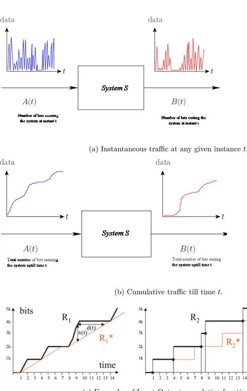
3.1 A simple system with one input and one output port. . . 28
3.2 Arrival and service curves. . . 29
3.3 Network calculus example. . . 31
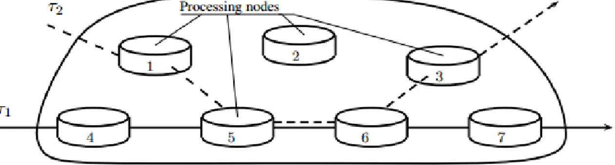
3.4 A distributed system. . . 33
3.5 Model used by Trajectory approach. . . 34
3.6 AFDX network for Trajectory approach example. . . 36
3.7 Identification of busy periods. . . 37
3.8 Maximizing the arrival time in last node. . . 39
3.9 Schematic view of sample AFDX network for NuSMV model. . . 44
xiv List of Figures
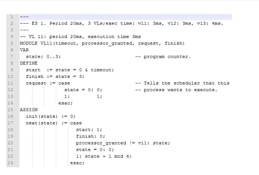
3.11 Modeling of VLs at the End System and Switch. . . 46
3.12 NuSMV code for timers. . . 47
3.13 Output of NuSMV model checker. . . 48
3.14 Example of AFDX Network configuration. . . 51
3.15 Offsets between VLs of one ES. . . 52
3.16 Timed Automata for an end system. . . 53
3.17 Asynchronous behavior of ESs. . . 53
3.18 Timed Automata for switch output port.. . . 54
3.19 Functions used for FIFO queue. . . 54
3.20 Timed Automata for Measuring VL. . . 55
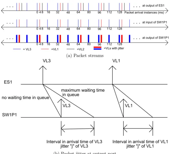
3.21 Packet arrival instances and how a delay at output port appears as jitter. . . 56
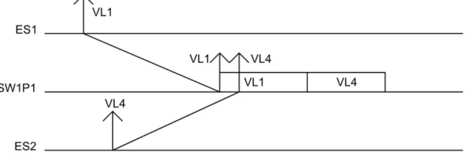
3.22 Serialization of VLs after passing through an output port. . . 57
3.23 Timed Automata for Serialized VL.. . . 57
3.24 Worst case scenario for VL1. . . 57
4.1 Illustration of a worst-case scenario . . . 63
4.2 Worst-case for a frame x. . . 65
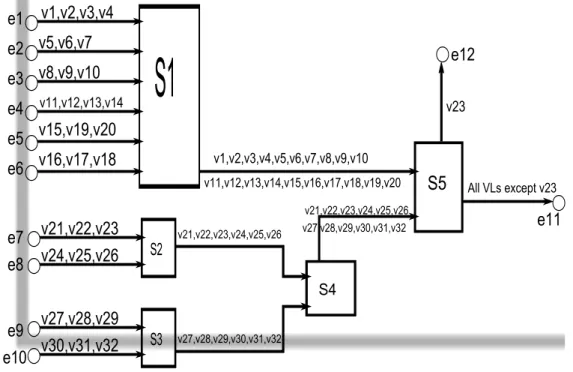
4.3 AFDX Network architecture for improved timed automata. . . 67
4.4 Sequence of e1 . . . 68
4.5 Timed automata of e1 . . . 69
4.6 Timed automata of e2 . . . 69
List of Figures xv
4.8 Timed automata of e9 . . . 71
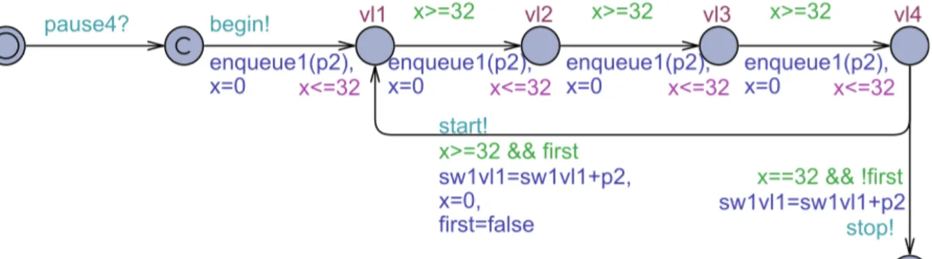
4.9 Timed automata of SW 1 . . . 71
4.10 Timed automata of SW 3 . . . 73
4.11 Timed automata of SW 5 . . . 74
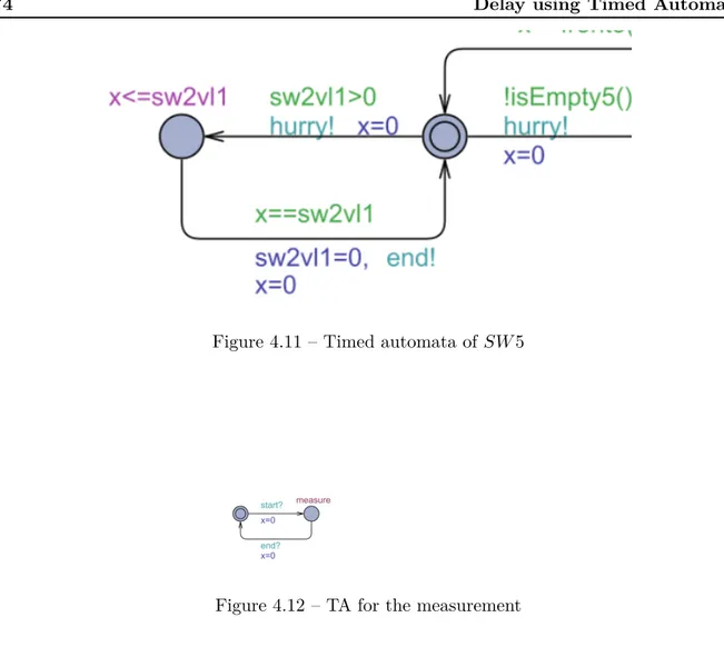
4.12 TA for the measurement . . . 74
4.13 TA for integer clocks . . . 76
4.14 A worst case scenario for v1 . . . 78
4.15 A simple timed automata. . . 80
4.16 Partial zone graph of the simple timed automata. . . 80
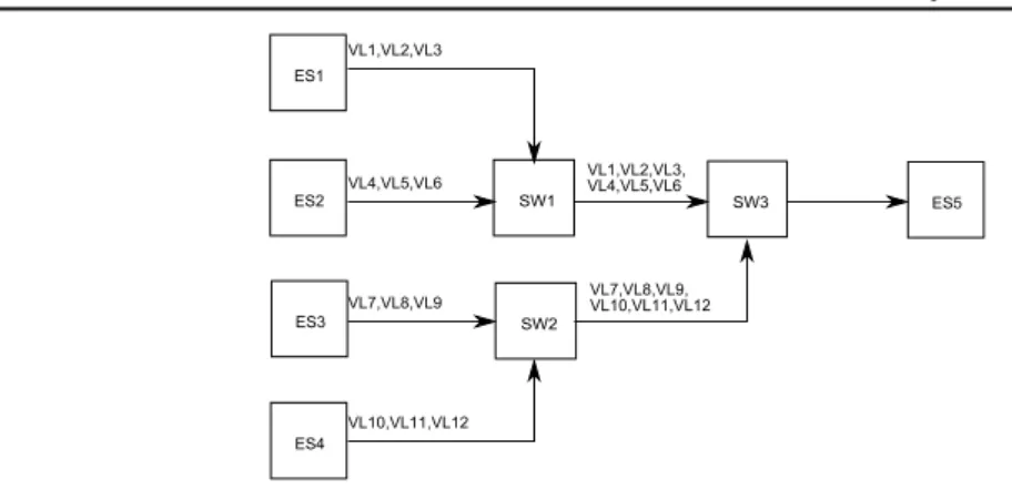
5.1 AFDX Network architecture. . . 85
5.2 Property 2. . . 88
5.3 Merging packet sequences and backlog calculation. . . 90
5.4 A simple AFDX Network of a small aircraft.. . . 91
5.5 Sequences generated at input of Switch S2. . . . 92
5.6 Construction of sequences at output of Switch S2 Port 1. . . . 93
5.7 Sequences generated at input of Switch S1. . . . 94
5.8 Construction of sequences at output of Switch S1 Port 1. . . . 95
5.9 Construction of sequences at output of Switch S3 Port 1. . . . 96
5.10 Network for reachable end to end delay illustration.. . . 99
5.11 Pessimism of computed upper bounds. . . 100
xvi List of Figures
5.13 Periodic vs Sporadic traffic . . . 101
5.14 Sporadic traffic in hyper period . . . 102
5.15 Order and size of packet in switch output port . . . 103
5.16 Idle time and queuing delay at a switch output port. . . 103
5.17 Idle time due to leaving VLs and its impact on packet under study. . . 105
5.18 Idle time and queuing delay at a switch output port. . . 106
6.1 AFDX Network of Airbus A380 aircraft. . . 114
6.2 Single VL and its paths with equivalent tree. . . 115
6.3 Connected Component of a graph which is equivalent to directly and indirectly interfering VLs. . . 116
6.4 VL10151 in isolation.. . . 117
6.5 VL10151 directly linked paths. . . 118
6.6 VL10151 all linked paths. . . 119
6.7 Software architecture. . . 121
6.8 Flows of AFDX network of case study. . . 122
6.9 Results of the case study compared to Trajectory approach. . . 125
6.10 Pessimism in Trajectory approach. . . 125
6.11 Results of the case study compared to Network Calculus. . . 126
6.12 Pessimism in Network Calculus.. . . 126
A.1 Comparison of Model Checking tools. . . 136
List of Figures xvii B.2 JPPF Grid architecture. . . 144
List of Tables
3.1 Exact worst-case delays. . . 58
4.1 AFDX network configuration data for improved timed automata . . . 67
4.2 Synchronization among different groups of VLs. . . 75
5.1 AFDX network configuration data . . . 84
5.2 End to End worst case delay for VL v3. . . 97
5.3 End to End worst case delay under approximation algorithm illustration. . . 99
5.4 Performance comparison of algorithm. . . 99
5.5 Configuration example for Algorithm 2. . . 110
6.1 AFDX network configuration: BAGs and packet sizes . . . 123
Chapter 1
Introduction
Contents
1.1 The Context . . . . 2 1.2 Contribution . . . . 4
In this era of modern science and technology, we rely heavily on the correct functioning of many Information and Communication Technology (ICT) systems. This trend is on the rise and while these systems are becoming more and more complex, at the same time they are massively encroaching on our daily life via the Internet and all kinds of embedded systems such as smart cards, hand-held computers, mobile phones, and high-end television sets. It is estimated that we are confronted with about 25 ICT devices on a daily basis [Baier 2008]. Many services such as electronic banking, on-line shopping (e-commerce) and smart card transactions are part of our routine life. The Internet alone accounts for about 1012 million US dollars cash flow.
Modern transportation systems such as cars, trains and airplanes spend about one fourth of their production costs in ICT systems. ICT systems have become universal and omnipresent. They play vital role in control of the stock exchange market, they are the heart of telephone switches, they constitute Internet technology, and they are crucial for several kinds of medical systems, transportation systems and manufacturing systems. Our heavy reliance on these embedded systems make them very important and their reliable and correct operation has become a prime priority. Not only we want a good performance in terms like response times and processing capacity, but also the absence of annoying errors is one of the major quality demands.
The correct behavior of ICT systems is vital not only for money and comfort but in many cases, also for our lives. We don’t like when our phones does not work properly or when our electronic gadgets reacts unexpectedly and wrongly to our issued commands. These software and hardware errors do not threaten our lives, but may have substantial financial consequences for the manufacturer. Examples are known where incorrect systems have caused valuable money loss to companies. The bug in Intel’s Pentium II floating-point division unit in the early nineties caused a loss of about 475 million US dollars to replace faulty processors, and severely damaged
2 Chapter 1. Introduction
Figure 1.1 – June 4, 1996; The Ariane-5 crashed 36 seconds after the launch due to a conversion of a 64-bit floating point into a 16-bit integer value.
Intel’s reputation as a reliable chip manufacturer. The software error in a baggage handling system postponed the opening of Denver’s airport for 9 months, at a loss of 1.1 million US dollar per day [Baier 2008].
Errors can be catastrophic too. Notorious examples in the past are the fatal defects in the control software of the Ariane-5 missile (figure 1.1), the Mars Pathfinder, and the airplanes of the Airbus family. Similarly software are also used for the process control of safety-critical systems such as chemical plants, nuclear power plants, traffic control and alert systems, and storm surge barriers. Consequently, bugs in such software can have disastrous impacts. For example, a software flaw in the control part of the radiation therapy machine “Therac-25" caused the death of six cancer patients between 1985 and 1987 as they were exposed to an overdose of radiation [Baier 2008].
All these examples remind us that it is very pertinent for any system to verify its correct intended operation and behaviour, specially for those which involve human lives. In this thesis, we strive for verification of an important avionics communication network known as Avionics Full-Duplex Switched Ethernet (AFDX). We will determine the exact worst case end to end communication delays of AFDX network. The context of this problem and brief background is presented in next section.
1.1 The Context
All modern aircraft have complex suit of on-board electronic devices used for various purposes, commonly referred to as Avionics Systems. Avionics systems of an aircraft are used in a wide
1.1. The Context 3 variety of different applications such as flight control, instrumentation, navigation, communica-tion etc. These avionics systems need to communicate between themselves and exchange data, hence building "Avionics networks". Over the years, demand for data exchange has risen rapidly and avionics networks have evolved from dedicated links to shared buses and from shared buses to switched networks such as AFDX. Avionics Full-Duplex Switched Ethernet (AFDX) [ AR-INC 664 2005] is an avionics data network for safety critical applications and hence requires a very strict verification of its correct functioning. One important aspect of this verification is the maximum end to end communication delay for different devices connected to the network. In any communication network, there is an end-to-end communication delay which occurs from the source generating a given message to the destinations receiving that message. For each message, this delay is composed of different parts: the transmission delays on links, the switching delays, the waiting times in output buffers. Knowing these delays is crucial for the overall system safety and reliability. However, finding the exact worst case delay for a given message is still an open problem, since every possible scenario has to be considered, leading to an intractable computation on any industrial configuration. Typically, this situation occurs in the context of avionics. Existing approaches for the computation of an exact worst-case delay in the context of the AFDX are based on model checking [Adnan 2010b,Charara 2006a] using Timed Automata [Alur 1994]. They cannot cope with configuration with more than ten VLs.
Many work has been devoted to the estimation of the worst-case delay for each message. By using techniques such as simulation and testing, it is possible to observe the network under study over long periods of times, thus considering a subset of all possible scenarios. Such an approach has been proposed in [Scharbarg 2009] for avionics networks. It provides an interval for the delay for each message. However, the delay for a message can be out of the obtained interval, since the approach does not consider all the possible scenarios. Consequently, simulation and testing do not provide us with exact worst case delays.
Analytical methods such as network calculus [Charara 2006a, Cruz 1991a] , [Cruz 1991b,
Fraboul 2002a, Le Boudec 2001, Li 2010] and trajectory approach [Bauer 2009, Bauer 2010,
Martin 2006a] are used to compute an upper bound on the maximum delay for each flow. They guarantee that the delay can never be more than the calculated upper bound. These computed bounds are used for network certification but are pessimistic and cause under utilization of the network. The exact worst case delay for each flow is somewhere between the maximum observed delay and the calculated upper bounds, as shown in figure 1.2. In [Bauer 2010], authors have done analysis of this pessimism by the computation of an under approximation of this delay and comparing it with the results of sure upper bounds calculated by Network Calculus and Trajectory approaches. In figure 1.2, the difference between exact maximum delay and under
4 Chapter 1. Introduction Time Distribution Upper Bound Exact mini mum de lay Exact maxim um del ay Observed m in delay Observed m ax delay
Worst case guarantee Exact worst case
Reachab le delay ge nerated by Algor ithm Pessimism Optimism
Figure 1.2 – AFDX network delays analysis.
approximation is the measure of optimism in algorithm used for under approximation while the difference between exact maximum delay and upper bound is the measure of pessimism in Network Calculus and Trajectory approaches used to calculate this bound. Without the knowledge of exact maximum delay, the difference between under approximation and upper bound is sum of optimism and pessimism between corresponding techniques. This gives us an estimation of pessimism in Network Calculus and Trajectory approaches.
Our aim, in this thesis, is to find exact worst case end to end communication delays. For this purpose we have explored existing tools and methodologies as well as developed new algorithms and tools where existing methods were not suitable for this task. The overview of this work is presented in the contribution section.
1.2 Contribution
The main objective of this thesis is to find exact worst case end to end communication delays of an AFDX network. For AFDX network, end to end communication delays can be approximated by using simulations, or they can be upper bounded by using analytical techniques such as Network Calculus or Trajectory approach. For computation of exact worst case delays, at present, we have only model checking approach but the model checking approach is limited only to small sized, proof of concept type networks and cannot analyze real life large sized industrial networks. These methods will be discussed in more detail in Chapter 3. Then, the problem is how to find exact worst case communication delays of large AFDX networks. Or, in other words, how can we improve models so that we are able to handle large networks. Also, another objective is to add local scheduling at the end systems in the computations which existing model checking approach doesn’t incorporate.
1.2. Contribution 5 Starting with the first model checking approach in [Charara 2006b], this approach can be improved: instead of analyzing the whole AFDX network simultaneously, only a part of the network can be considered and "divide and conquer" method can be used. This have been done in [Adnan 2010a] and presented in [Adnan 2010b, Adnan 2010c].The idea is to consider one output port at a time and compute worst case delay at the port under study. This approach is successful in handling larger networks than the existing approach but it does not compute exact worst case delays for every scenario. Due to the port by port analysis approach, it is optimistic in certain cases where worst case delay on one port does not lead to overall end to end worst case delay. This is discussed in further detail in Chapter 3.
In this PhD Thesis, we propose to improve the Timed Automata models in two directions. First, scheduling of VLs at a local end system using offsets and asynchronous behaviour among all end systems have been added into the model, making the model of the AFDX network more realistic. Secondly, to make models efficient in resource (memory + computation) usage and to reduce search space, in order to cope with larger AFDX networks. In this context, we exploit AFDX network properties to reduce search space by considering only those cases which can be candidate for the worst case end to end delay. A first implementation considering this search space reduction has been presented in [Adnan 2011a, Adnan 2012]. A general purpose model checker, UPPAAL, is used for the developed timed automata models.
The models are detailed enough to capture periodic and sporadic flows with any BAG values. They also support local scheduling at each end system by using offsets. AFDX network with upto 32 VLs can be handled with this approach. This work is presented in more detail in Chapter 4.
At this point, we were still not able to compute worst case end to end delays of a real life industrial scale AFDX network by model checking. This is due to inherent exponential increase of state space in any model checking approach. But we were convinced that use of a general purpose model checker is also hampering our efforts to analyze larger networks. Therefore, we decided to use an approach which is more suited to AFDX network analysis. For this purpose, we started to develop a tool from scratch, which will allow us to exhaustively check all the cases which can be candidate for the worst case end to end delays in the AFDX network. This tool uses the same methodology and algorithms of state space reduction as used in Timed Automata based modeling approach discussed before. This work was presented in [Adnan 2011b]. The results are much better as compared to Timed Automata approach using UPPAAL software. We are able to compute end to end communication delays of a network which is twice the size of what Timed Automata based approach can handle. This approach is discussed in detail in Chapter 5.
6 Chapter 1. Introduction We continued to pursue our main goal to analyze an industrial size AFDX network. With home made tool, we are at liberty to modify and change the software as required. We developed some algorithms and exploited more properties of AFDX network in order to reduce the search space to an extent where we were able to analyze industrial configuration of the AFDX network. We used this tool to study the end to end communication delays of a real life AFDX network, used on Airbus A380 aircraft. We are now able to compute end to end communication delays of an industrial sized network with about 1000 VLs having 6412 individual paths and more than 100 end systems. We are able to analyze all the VLs of this industrial AFDX network but not all the paths. We can analyze more than 60% paths. The reduction of state space is discussed in Chapter 5.5and the case study of Airbus A380 network is presented in Chapter 6.
Our contribution in this thesis is to be able to find exact worst case end to end communication delays for large industrial size AFDX network and compare it with existing results to evaluate real pessimism of corresponding approaches.
Chapter 2
Background: System Verification
and AFDX Network
Contents 2.1 System Verification . . . . 7 2.1.1 Software Verification . . . 10 2.1.2 Hardware Verification . . . 10 2.1.3 Behavioral Verification . . . 11 2.2 Model Checking . . . 12 2.2.1 Formal Methods . . . 12 2.2.2 Model-based Verification. . . 13
2.2.3 History of Model Checking . . . 15
2.2.4 Application of Model Checking in Networks . . . 15
2.2.5 Characteristics of Model Checking . . . 15
2.3 AFDX Network . . . 18
2.3.1 History of Aircraft Data Networks (ADN) . . . 19
2.3.2 Overview of AFDX . . . 19
2.3.3 Virtual Links (VL) . . . 21
In this chapter we will discuss about system verification and different methodologies available for this purpose. We will also talk about AFDX network in detail; how it works and what are the main building blocks.
2.1 System Verification
The complexity of ICT systems has increased with the advancement in technology. They have evolved from standalone systems to distributed systems; connecting and interacting with several
8 Chapter 2. Background: System Verification and AFDX Network System Specifications Design Process Prototype Properties Verification Error No Error
Figure 2.1 – Schematic view of system verification process.
other components and systems. This makes them more prone to errors as the probability and number of defects increases exponentially with the number of interacting system components. Increased complexity also makes it difficult for developers to debug and check systems for potential errors. In particular, phenomena such as concurrency and non-determinism that are central to modeling interacting systems turn out to be very hard to handle with standard techniques. Hence a lot of research is being carried out and efforts are being put in order to check Hardware and Software for correctness as well as compliance to it’s specifications. These efforts are generally referred to as “System Verification" and is an active topic of research.
System verification techniques are integral part of all ICT system developments. Currently, the emphases of scientific community is on developing more reliable and accurate system ver-ification techniques. In simple words, system verver-ification is used to establish that the design or product under consideration satisfies certain properties. The properties to be validated are mostly obtained from the system’s specification and can be quite elementary, e.g., to verify that the system should never be able to reach a situation in which no progress can be made (a dead-lock scenario). The specifications describe what the system has to do and what not, and thus constitutes the basis for any verification activity. A defect is found once the system does not fulfill one of the specification’s properties. The system is considered to be “correct" whenever it satisfies all properties obtained from its specification. So correctness is always relative to a specification, and is not an absolute property of a system. A schematic view of verification process is depicted in figure 2.1.
Today’s systems are very complex in it’s nature and mostly comprise of interconnected sub systems. System verification is a vast field and can be further subdivided into major domains such as:
2.1. System Verification 9 • Software verification
• Hardware verification • Behavioral verification
There are different methodologies being used for system verification. These methodologies can be specific to one domain or applicable to more than one domain. These include:
• Measurements • Tests
• Simulations • Model Checking
In the context of this thesis, the verification of worst case end to end communication delays falls under behavioral verification domain. For this verification, all of the above mentioned methodologies can be used with varying degree of confidence or surety. Measurements are the quantitative indicators of the properties and performance criteria of the system under study. They can be very useful during the development phase or for troubleshooting. Tests are integral part of any system development. A system undergoes many tests from its inception to final product. At each state different tests are performed. Results of these tests dictates the progress to next level of development. Simulation is replication of a real world process or system over time. This replication should be as close to real world system as possible for better results. Simulations are used to investigate behaviour of the system and to validate proper functionality without using the actual system. Tests and simulations are quite similar in nature except that in tests, actual system is used. All of the above mentioned methodologies i.e measurements, tests and simulations only provide data at a particular instance under specific conditions, which means it does not verify system for all possible situations or scenarios. Therefore these methodologies can discover many anomalies in the system understudy but they can not verify that all the possible situations and scenarios have been covered. There is always a chance that a rare anomaly or event has not been tested. For covering all possible cases or scenarios, model checking is used. Model checking, for a given model of a system, exhaustively and automatically checks whether this model meets a given specification. Simulation can also check all possible cases or scenarios, and such simulation is referred to as Exhaustive Simulation. So, for 100% coverage of all possible scenarios, model checking and exhaustive simulation are the two methodologies which can be used. In the context of this thesis, for exact worst case end to end communication
10 Chapter 2. Background: System Verification and AFDX Network delays, we will use both model checking and exhaustive simulation. These methodologies will be discussed in more detail in the next sections.
2.1.1 Software Verification
Software verification is a process of checking system’s software for it’s compliance with specifi-cations and expected requirements. Peer reviewing and testing are the major “software verifi-cation" techniques used in practice. A “peer review" refers to a software inspection carried out by a team of software engineers that preferably has not been involved in the development of software under review. The code of software is not executed but analyzed statically. Empirical studies indicate that peer review provides an effective technique that catches around 60% of the errors [Boehm 2001]. Despite its almost complete manual nature, peer review is thus a rather useful technique. Due to its static nature, experience has shown that subtle errors such as concurrency and algorithm defects are hard to catch using peer review.
“Software testing" is a significant part of any software engineering project [Whittaker 2000]. As opposed to peer review, which analyzes code statically without executing it, testing is a dynamic technique that actually runs the software. Testing takes the piece of software under consideration and provides its compiled code with inputs, called tests. Correctness is thus deter-mined by forcing the software to traverse a set of execution paths, sequences of code statements representing a run of the software. Based on the observations during test execution, the actual output of the software is compared to the output as documented in the system specification. Although test generation and test execution can partly be automated, the comparison is usu-ally performed by human beings. The main advantage of testing is that it can be applied to all sorts of software, ranging from application software (e.g., e-business software) to compilers and operating systems. As exhaustive testing of all execution paths is practically in-feasible; in practice only a small subset of these paths is treated. Testing can thus never be complete. That is to say, testing can only show the presence of errors, not their absence.
2.1.2 Hardware Verification
“Hardware Verification" is vital for preventing errors in hardware design. Hardware is subject to high fabrication costs; fixing defects after delivery to customers is difficult, and quality expectations are high. Whereas software defects can be repaired by providing users with patches or updates, hardware bug fixes after delivery to customers are very difficult and mostly require re-fabrication and redistribution. This has immense economic consequences. As mentioned
2.1. System Verification 11 earlier, the replacement of the faulty Pentium II processors caused Intel a loss of about $ 475 million. It is not surprising that chip manufacturers invest a lot in getting their designs right. Hardware verification is a well-established part of the design process. Emulation, simulation, and structural analysis are the major techniques used in hardware verification.
“Structural analysis" comprises several specific techniques such as synthesis, timing analysis, and equivalence checking. “Emulation" is a kind of testing. A re-configurable generic hardware system (the emulator) is configured such that it behaves like the circuit under consideration and is then extensively tested. As with software testing, emulation amounts to providing a set of stimuli to the circuit and comparing the generated output with the expected output as laid down in the chip specification. To fully test the circuit, all possible input combinations in every possible system state should be examined. This is impractical and the number of tests needs to be reduced significantly, yielding potential undiscovered errors. With “simulation", a model of the circuit at hand is constructed and simulated. Models are typically provided using hardware description languages such as V erilog or V HDL that are both standardized by IEEE. Based on stimuli, execution paths of the chip model are examined using a simulator. These stimuli may be provided by a user, or by automated means such as a random generator. A mismatch between the simulator’s output and the output described in the specification determines the presence of errors. Simulation is like testing, but is applied to models. It suffers from the same limitations, though: the number of scenarios to be checked in a model to get full confidence goes beyond any reasonable subset of scenarios that can be examined in practice.
2.1.3 Behavioral Verification
Behavior of a system refers to it’s expected outputs for a given set of assumed inputs. In simple words, Behavioral Verification is the process of verification of system’s “behavior" under given conditions. System’s behavior is combined effect of its software and hardware functioning. Even though a system is verified separately for it’s software and hardware, it is equally important to verify the system at more abstract and conceptual levels. For example, communication protocols, compliance of specified rules, and interaction among subsystems must be verified before starting development of hardware and software for each individual subsystem. Behavioral verification requires a “model" of the system. This model is a formal way of describing the system over which we can use certain queries and properties to verify it’s behavior. Different tools incorporating various techniques exist which help in modeling a system for it’s behavioral verification such as TINA, NuSMV, SPIN, UPPAAL etc. A comprehensive list of such tools can be consulted in Appendix A.
12 Chapter 2. Background: System Verification and AFDX Network It must be noted that none of the software and hardware verification techniques described earlier gives us the 100% confidence about system correctness due to the same limitation of unreasonably large set of possible scenarios. If we need absolute surety of our design, then we must find a way to test all possible scenarios and that’s where model checking helps us. Model checking approach searches all possible scenario exhaustively to prove correctness of the model under test. An important aspect of model checking is that it’s as good as the model itself, i.e we must ensure that the model correctly represents the system before we start the model checking. In the following sections, basic theory of model checking is presented. The details of available model checking software, called “model checkers", and their application to AFDX network is described in Chapter 3.2and Chapter 4respectively. Further discussion about model checking is presented in Appendix A.
2.2 Model Checking
In general more time and effort are spent on verification than on construction in software and hardware design of complex systems. Naturally, many techniques are sought to reduce and ease the verification efforts while increasing their coverage. One such technique is the use of “Formal methods" which is known to offer a large potential to obtain an early integration of verification in the design process, to provide more effective verification techniques, and to reduce the verification time.
2.2.1 Formal Methods
To put it in a nutshell, formal methods can be considered as“the applied mathematics for model-ing and analyzmodel-ing ICT systems". Their aim is to establish system correctness with mathematical rigor. Their great potential has led to an increasing use by engineers of formal methods for the verification of complex software and hardware systems. Besides, formal methods are one of the “highly recommended" verification techniques for software development of safety critical systems according to, e.g., the best practices standard of the IEC (International Electro-technical Com-mission) and standards of the ESA (European Space Agency). The resulting report [Baier 2008] of an investigation by the FAA (Federal Aviation Authority) and NASA (National Aeronautics and Space Administration) about the use of formal methods concludes that “Formal methods should be part of the education of every computer scientist and software engineer, just as the appropriate branch of applied maths is a necessary part of the education of all other engineers."
2.2. Model Checking 13 During the last two decades, research in formal methods has led to the development of some very promising verification techniques that facilitate the early detection of defects. These techniques are accompanied by powerful software tools that can be used to automate various verification steps. Investigations have shown that formal verification procedures would have revealed the exposed defects in, e.g., the Ariane-5 missile, Mars Pathfinder, Intel’s Pentium II processor, and the Therac-25 therapy radiation machine.
2.2.2 Model-based Verification
Model-based verification techniques are based on models describing the possible system behavior in a mathematically precise and unambiguous manner. It turns out that prior to any form of verification, the accurate modeling of systems often leads to the discovery of incompleteness, ambiguities, and inconsistencies in informal system specifications. Such problems are usually only discovered at a much later stage of the design. The system models are accompanied by algorithms that systematically explore all states of the system model. This provides the basis for a whole range of verification techniques ranging from an exhaustive exploration (model checking) to experiments with a restrictive set of scenarios in the model (simulation), or in reality (testing). Due to unremitting improvements of underlying algorithms and data structures, together with the availability of faster computers and larger computer memories, model-based techniques that a decade ago only worked for very simple examples are nowadays applicable to realistic designs. As the starting point of these techniques is a model of the system under consideration, we have as a given fact that any verification using model-based techniques is only as good as the model of the system.
Model checking is a verification technique that explores all possible system states, commonly known as state-space, in a brute-force manner. Similar to a computer chess program that checks possible moves, a model checker, the software tool that performs the model checking, examines all possible system scenarios in a systematic manner. In this way, it can be shown that a given system model truly satisfies a certain property. It is a real challenge to examine the largest possible state spaces that can be treated with current means, i.e., processors and memories. State-of- the-art model checkers can handle state spaces of about 108 to 109 states with explicit
state-space enumeration. Using clever algorithms and tailored data structures, larger state spaces (1020 up to even 10476 states) can be handled for specific problems [Straunstrup 2000].
Even the subtle errors that remain undiscovered using emulation, testing and simulation can potentially be revealed using model checking.
14 Chapter 2. Background: System Verification and AFDX Network
Requirements System
Formalizing Modeling
Property Specification System Model
Model Checking
Satisfied Violated Simulation Error Location
Figure 2.2 – Schematic view of Model Checking process.
the generated result OK?, Can the system reach a deadlock situation? e.g., when two concurrent programs are waiting for each other and thus halting the entire system? But also timing properties can be checked: Can a deadlock occur within 1 hour after a system reset?, or, Is a response always received within 8 minutes? Model checking requires a precise and unambiguous statement of the properties to be examined. As with making an accurate system model, this step often leads to the discovery of several ambiguities and inconsistencies in the informal documentation. For instance, the formalization of all system properties for a subset of the ISDN user part protocol revealed that 55% (!) of the original, informal system requirements were inconsistent [Holzmann. 1994]. The system model is usually automatically generated from a model description that is specified in some appropriate dialect of programming languages like C or Java or hardware description languages such as Verilog or VHDL. Note that the property specification prescribes what the system should do, and what it should not do, whereas the model description addresses how the system behaves. The model checker examines all relevant system states to check whether they satisfy the desired property. If a state is encountered that violates the property under consideration, the model checker provides a counterexample that indicates how the model could reach the undesired state. The counterexample describes an execution path that leads from the initial system state to a state that violates the property being verified. With the help of a simulator, the user can replay the violating scenario, in this way obtaining useful debugging information, and adapt the model (or the property) accordingly (see Figure 2.2).
2.2. Model Checking 15
2.2.3 History of Model Checking
Model checking originates from the independent work of two pairs in the early eighties: Clarke and Emerson [Clarke 1981] and Queille and Sifakis [Queille 1982]. The term model checking was coined by Clarke and Emerson. The brute-force examination of the entire state space in model checking can be considered as an extension of automated protocol validation tech-niques by Hajek [Hajek 1978] and West [West 1978,West 1989]. While these earlier techniques were restricted to checking the absence of deadlocks or livelocks, model checking allows for the examination of broader classes of properties. Introductory papers on model checking can be found in [Clarke 1996a,Clarke 2000,Clarke 1996b, Merz 2001, Wolper 1995]. The limitations of model checking were discussed by Apt and Kozen [Apt 1986]. More information on model checking is available in the earlier books by Holzmann [Holzmann 1990], McMillan [ McMil-lan 1993], and Kurshan [Kurshan 1994] and the more recent works by Clarke, Grumberg, and Peled [Clarke 1999], Huth and Ryan [Huth 1999], Schneider [Schneider 2004], and Bérard et al. [Bérard 2001]. Automated analysis of designs, in particular verification by model checking, has recently been described by Ruys and Brinksma in [Ruys 2003].
2.2.4 Application of Model Checking in Networks
Model checking has been used for verification of different systems in the past. In the do-main of networks, it has been used to verify redundant media extension of Ethernet PowerLink [Steve 2007]. It has also been used in networked automation systems [Ruel 2008] and in func-tional analysis of real-time protocol in an networked control system [Fidge 2006]. For Integrated Modular Avionics (IMA)[ARINC 653 1997] , the bounds on end to end functional delays have been studied in [Lauer 2010]. All these applications of model checking are different than what we do in this thesis. None of the above approaches find exact worst case communication delays over the network. Most of these approaches use either an abstraction of the network with basic functionality such as NetworkOK, NetworkCongested, OnTime, TooLate as in [Fidge 2006] or they use upper bounds of network communication delays calculated by Network Calculus or Trajectory approach as in [Lauer 2010].
2.2.5 Characteristics of Model Checking
Model Checking can be defined as “an automated technique that, given a finite-state model of
16 Chapter 2. Background: System Verification and AFDX Network state in) that model." The next section briefly explains the general process of model checking followed by it’s advantages, limitations and role in system development cycle.
2.2.5.1 Model Checking Process
Model checking process can be divided in following different phases: • Modeling phase:
– model the system under consideration using the model description language of the model checker at hand;
– as a first sanity check and quick assessment of the model perform some simulations; – formalize the property to be checked using the property specification language. • Running phase: run the model checker to check the validity of the property in the system
model.
• Analysis phase:
– is property satisfied? If yes then check next property (if any);
– is property violated? If yes then system did not respect its specification. Therefore: 1. analyze generated counterexample by simulation;
2. refine the model, design, or property; 3. repeat the entire procedure.
– out of memory? If yes then try to revise the abstraction level of the model to reduce its size and try again.
2.2.5.2 Strengths and Weaknesses of Model checking Following are the main strengths of model checking approach:
• It is a general verification approach that is applicable to a wide range of applications such as embedded systems, software engineering, and hardware design.
• It supports partial verification, i.e., properties can be checked individually, thus allowing focus on the essential properties first. No complete requirement specification is needed.
2.2. Model Checking 17 • It is not vulnerable to the likelihood that an error is exposed; this contrasts with testing
and simulation that are aimed at tracing the most probable defects.
• It provides diagnostic information in case a property is invalidated; this is very useful for debugging purposes.
• It is a potential “push-button" technology; once the model has been developed, the use of model checking tools requires neither a high degree of user interaction nor a high degree of expertise.
• It enjoys a rapidly increasing interest by industry; several hardware companies have started their in-house verification labs, job offers with required skills in model checking frequently appear, and commercial model checkers have become available.
• It can be easily integrated in existing development cycles; its learning curve is not very steep, and empirical studies indicate that it may lead to shorter development times. • It has a sound and mathematical underpinning; it is based on theory of graph algorithms,
data structures, and logic.
Following are the weaknesses of model checking:
• It is mainly appropriate to control-intensive applications and less suited for data intensive applications as data typically ranges over infinite domains.
• Its applicability is subject to decidability issues; for infinite-state systems, or reasoning about abstract data types (which requires undecidable or semi-decidable logics), model checking is in general not effectively computable.
• It verifies a system model, and not the actual system (product or prototype) itself; any obtained result is thus as good as the system model. Complementary techniques, such as testing, are needed to find fabrication faults (for hardware) or coding errors (for software). This highly depends on the level of abstraction in the model of the system.
• It checks only stated requirements, i.e., there is no guarantee of completeness. The validity of properties that are not checked cannot be judged.
• It suffers from the state-space explosion problem, i.e., the number of states needed to model the system accurately may easily exceed the amount of available computer memory. Despite the development of several very effective methods to combat this problem, models of realistic systems may still be too large to fit in memory.
18 Chapter 2. Background: System Verification and AFDX Network • Its usage requires some expertise in finding appropriate abstractions to obtain smaller
system models and to state properties in the logical formalism used.
• It is not guaranteed to yield correct results: as with any tool, a model checker may contain software defects.
• It does not allow checking generalizations: in general, checking systems with an arbitrary number of components, or parameterized systems, cannot be treated. Model checking can, however, suggest results for arbitrary parameters that may be verified using proof assistants.
Model checking has great potential in system verification and removing rare to find bugs. It can formally verify properties of the system, and it can be used to check correct behavior of the system. Model checking is the choice when we want a complete verification of the system which simulations can not provide. Model checking considers all possible cases, and hence we can apply it to AFDX network in order to find exact end to end communication delays. We will discuss the application of this technique to find exact end to end communication delays of AFDX network [ARINC 664 2005] in coming sections (Chapter3.2.1, Chapter4), but first let’s describe AFDX Network.
2.3 AFDX Network
All modern aircraft have complex suit of on-board electronic devices used for various purposes, commonly referred to as Avionics Systems. Avionics systems of an aircraft are used in a wide variety of different applications such as flight control, instrumentation, navigation, communi-cation etc. These avionics systems need to communicate between themselves and exchange data, hence building "Avionics networks". Over the years, demand for data exchange has risen rapidly and avionics networks have evolved from dedicated links to shared buses to switched networks such as AFDX. Avionics Full-Duplex Switched Ethernet (AFDX) [ARINC 664 2005]is a data network for safety critical applications that utilizes dedicated bandwidth while providing deterministic Quality of Service (QoS). AFDX is based on IEEE 802.3 Ethernet technology and utilizes commercial off-the-shelf (COTS) components with certain constraints applied. It is described specifically by Part 7 of the ARINC 664 Specification, as a special case of a profiled version of an IEEE 802.3 network per parts 1 & 2, which defines how Commercial Off-the-Shelf networking components will be used for future generation Aircraft Data Networks (ADN). The six primary aspects of AFDX include full duplex, redundancy, deterministic, high speed perfor-mance, switched and profiled network.
2.3. AFDX Network 19
2.3.1 History of Aircraft Data Networks (ADN)
Prior to AFDX, Aircraft Data Networks utilized primarily the ARINC 429 standard. This standard, developed over thirty years ago and still widely used today, has proven to be highly reliable in safety critical applications. This ADN can be found on a variety of aircraft from both Boeing and Airbus, including the B737, B747, B757, B767 and Airbus A330, A340, A380 and the upcoming A350. ARINC 429 utilizes a unidirectional bus with a single transmitter and up to twenty receivers. A data word consists of 32 bits communicated over a twisted pair cable using the Bipolar Return-to-Zero Modulation. There are two speeds of transmission: high speed operates at 100 kbit/s and low speed operates at 12.5 kbit/s. ARINC 429 operates in such a way that its single transmitter communicates in a point-to-point connection, thus requiring a significant amount of wiring which amounts to added weight.
Another standard, ARINC 629, introduced by Boeing for the 777 provides increased data speeds of up to 2 Mbit/s and allowing a maximum of 120 data terminals. This ADN operates without the use of a bus controller thereby increasing the reliability of the network architecture. The drawback of this system is that it requires custom hardware which can add significant cost to the aircraft. Because of this, other manufacturers did not openly accept the ARINC 629 standard.
ARINC 664 is defined as the next-generation aircraft data network (ADN). It is based upon IEEE 802.3 Ethernet and utilizes commercial off the shelf hardware thereby reducing costs and development time. AFDX builds on this standard, as is formally defined in Part 7 of the ARINC 664 specification. AFDX was developed by Airbus Industries for the A380. It has since been accepted by Boeing and is used on the Boeing 787 Dreamliner. AFDX bridges the gap on reliability of guaranteed bandwidth from the original ARINC 664 standard. It utilizes a cascaded star topology network, where each switch can be bridged together to other switches on the network. By utilizing this form of network structure, AFDX is able to significantly reduce wire runs thus reducing overall aircraft weight. Additionally, AFDX provides dual link redundancy and Quality of Service (QoS). Figure 2.3 compares basic architecture of ARINC and AFDX networks.
2.3.2 Overview of AFDX
AFDX adopted concepts (token bucket) from the telecom standard, Asynchronous Transfer Mode (ATM), to fix the shortcomings of IEEE 802.3 Ethernet such as in-deterministic behavior of ”Carrier sense multiple access with collision detection (CSMA/CD)". By adding key elements
20 Chapter 2. Background: System Verification and AFDX Network
2.3. AFDX Network 21 from Asynchronous Transfer Mode (ATM) to those already found in Ethernet, and constraining the specification of various options, a highly reliable Full-Duplex deterministic network is cre-ated providing guaranteed bandwidth and Quality of Service. Through the use of Full-Duplex Ethernet, the possibility of transmission collisions is eliminated. A highly intelligent switch, common to the AFDX network, is able to buffer transmission and reception packets. Through the use of twisted pair or fiber optic cables, Full-Duplex Ethernet uses two separate pairs or strands for transmit and receiving data. AFDX extends standard Ethernet to provide high data integrity and deterministic timing. Further a redundant pair of networks is used to improve the system integrity. Figure 2.4 depicts a generic AFDX network. It specifies inter-operable functional elements at the following OSI Reference Model layers:
• Data Link (MAC and Virtual Link addressing concept); • Network (IP and ICMP);
• Transport (UDP and optionally TCP)
• Application (Network) (Sampling, Queuing, SAP, TFTP and SNMP).
The main elements of an AFDX network are:
• AFDX End Systems
• AFDX Switches
• AFDX Links
2.3.3 Virtual Links (VL)
The central feature of an AFDX network are its Virtual Links (VL). In one abstraction, it is possible to visualize the VLs as an ARINC 429 style network each with one source and one or more destinations as shown in figure 2.5. Virtual Links are unidirectional logic path from the source end-system to all of the destination end-systems. Unlike that of a traditional Ethernet switch which switches frames based on the Ethernet destination or MAC address, AFDX routes packets using a Virtual Link ID. The Virtual Link ID is a 16-bit Unsigned integer value that follows the constant 32-bit field. The switches are designed to route an incoming frame from one, and only one, End System to a predetermined set of End Systems. There can be one or more receiving End Systems connected within each Virtual Link. Each Virtual Link is allocated
22 Chapter 2. Background: System Verification and AFDX Network
Figure 2.4 – AFDX network (courtesy condor engineering inc.)
dedicated bandwidth known as Bandwidth Allocation Gap (BAG) with the total amount of bandwidth defined by the system integrator. However total bandwidth can not exceed the maximum available bandwidth on the network. Bi directional communications must therefore require the specification of a complimentary VL. Each VL is frozen in specification to ensure that the network has a designed maximum traffic, hence performance. Also the switch, having a VL configuration table loaded, can reject any erroneous data transmission that may otherwise swamp other branches of the network. Additionally, there can be sub-virtual links (sub-VLs) that are designed to carry less critical data. Sub-virtual links are assigned to a particular Virtual Link. Data is read in a round robin sequence among the Virtual Links with data to transmit. Also sub-virtual links do not provide guaranteed bandwidth or latency due to the buffering, but AFDX specifies that latency is measured from the traffic regulator function anyway.
A generic AFDX switch architecture is shown in figure 2.6. Each switch has filtering, policing, and forwarding functions that should be able to process at least 4096 VLs (this seems like a system specific derived requirement in part 7). Therefore, in a network with multiple switches (cascaded star topology), the total number of Virtual Links is nearly limitless. There is no specified limit to the number of Virtual Links that can be handled by each End System (except the one imposed by the VL ID field size in the packet header), although this will be determined by the BAG rates and max frame size specified for each VL versus the Ethernet data rate. However, the number sub-VLs that may be created in a single Virtual Link is limited to four. The switch must also be non-blocking at the data rates that are specified by the system integrator, and in practise this may mean that the switch shall have a switching capacity that is the sum of all of its physical ports.
2.3. AFDX Network 23
Figure 2.5 – AFDX virtual links.
24 Chapter 2. Background: System Verification and AFDX Network The AFDX network is being adapted in many modern aircraft. At present it is being used in Airbus A380, Boeing 787, Airbus A400M, Airbus A350, Sukhoi Superjet 100, AgustaWestland AW101, AgustaWestland AW149 and some others.