A Quadrangular Shell Finite Element for Concrete and Steel Structures
Subjected to Fire
DlDIER TALAMONA
University of Ulster, School of the Built Environment FireSERT, Newtownabbey, BT37 OQB, UK
JEAN-MARC FRANSSEN
Dpt M&S, University of Liege 1 Chemin des Chevreuils, 4000 Liege 1, Belgium
ABSTRACT: SAFIR is finite element software for the thermal and mechanical analysis of structures exposed to
fire. For mechanical analysis, a library of different elements is available in SAFIR: truss, beam, etc. In order to increase SAFIR's capabilities, a quadrangular shell element has been implemented. This element is not subject to 'locking' (or over-stiffness) in the case of 'membrane bending'. Different material models can be used. These are plasticity models based on the von Mises surface (for isotropic materials), plus a Rankine tension cut off for concrete. The parameters of the models as well as the hardening laws have been chosen in such a way as to fit the recommendations of Eurocode 2 and 3 for uniaxial stress-strain curves of concrete and steel under fire condition. Some verification and validation examples at room and at elevated temperatures are presented.
KEY WORDS: SAFIR, finite element, shell, thermal, fire exposure, structures in fire.
INTRODUCTION
A STANDARD FIRE TEST is the most common way to justify the fire resistance of a structural element. Over the last three decades, a number of fire tests have been performed, which have generated a large database and contributed to the understanding of the behavior of structural elements under fire condition. These tests have been used to calibrate and validate finite element software. Numerous finite element types are available for this software and the proper element has to be used, depending on the structure to be meshed. This requires a good understanding of the physical problem by the user and knowledge of the capabilities (or limitations) of the finite elements available in the software library.
SAFIR is finite element software that was developed in the 1990s by Franssen at the University of Liege. This software is used for the thermal and mechanical analysis of structures exposed to fire. Usually, thermal calculations are run first to determine the transient temperatures in the structure exposed to fire. Then, the mechanical analysis is performed in a step-by-step procedure consisting of subsequent static analyses, using the temperatures calculated during the thermal analysis. This procedure allows modeling of the mechanical behavior of a structure during the different stages of the fire (preflashover, postflashover, and decay).
The most common finite elements used to mesh a civil engineering structure are beams, trusses, and shells. Now, a quadrangular element has been introduced in SAFIR. The quadrangular element, its capabilities, and some validation examples, are presented in this article.
FORMULATION OF THE SHELL ELEMENT
The quadrangular element is based on the element used in the software FINELG developed by de Ville at the University of Liege and the Bureau d'Etudes Greisch [1-5] for use at room temperature. It has been modified as required for high temperature situations.
Reference Configuration
For this nonplanar quadrangular element, the z-axis is obtained as follows:
Another way to define the z-axis could be to find the best plane reference for the element:
It can be shown that, if the coefficients α2 and α3 are chosen in such a way that the orientation of the reference plane minimizes the slopes between the element and the plane, then the z-axis defined by Equation (1) is perpendicular to the plane. This proves that Equation (1) also minimizes the slopes.
Figure 1. Reference configuration.
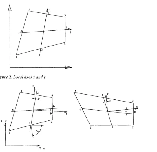
Figure 2. Local axes x and y.
In Equation (2), α1 is still undetermined. It will be chosen in such a way that the plane of reference goes through the center of gravity of the quadrangle.
As it will be seen later, the membrane strains are not complete polynomials, so the results will be dependent on the choice of the x, y local axes. The angle between the x-axis and bd is imposed to be equal to the angle between
ac and the y-axis (Figure 2). This determines the choice of the x-, y-axes. For a rectangular element, this gives
local axes parallel to the edges.
The Membrane Behavior
The classical quadratic membrane displacement field is enlarged to cubic degree by means of cubic (along ξ and
η) functions and constants Ay. The development is similar to the one found in Allman [6] for a triangular
The functions ψij are chosen to be orthogonal to øij with respect to integration over the quadrangle.
To improve the convergence, the shear strains are assumed to be constant over the element. After some calculation, the following equations are found:
Flexural Behavior
The formulation used is a Discrete Kirchhoff theory Quadrangular (DKQ). This element is fully described in [8-11]. The principle of this element will be briefly recalled here. The presentation is slightly different from the one given in [8-10].
The out-of-plane displacement and the rotations are parabolic over each side:
Ni are the shape functions and they depend on the parametric coordinates ξ and η. Along the side i, the
out-of-plane displacement is given by:
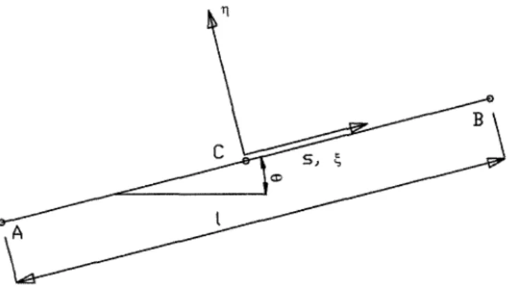
wA, wB,and wC are the normal displacements along z-axis normal to x-y plane (at the points A, B, and C). If we look at one edge of the element, for example the edge from node 1 to node 2, node 1 is called A, node 2 is called B, and the midpoint is called C, see Figure 3. The contribution of the shear strain energy is neglected.
To reproduce thin plate theory, the Kirchhoff condition is imposed at selected points. In this element, the Kirchhoff constraints are imposed along the edges.
Figure 3. Local axis on one side.
The shear strain γsz at each of the two Gauss integration points along the sides is set to zero, i.e., weighted
averages of the shear strain are set to zero:
In-plane Rotation
The in-plane rotation or sixth degree of freedom (DOF) of this element is described by Jetteur [12] and Jaamei [13]. A common method used to calculate the in-plane stiffness is to add a small stiffness to this DOF. As this can lead to incorrect results, the method has been disregarded and it has been decided to include the in-plane rotation as an effective DOF [12,13]. The approach followed for this element is very similar to the one used by Allman [6], Carpenter et al. [14], and Taylor and Simo [15].
The interaction between the membrane stiffness (linked to the rotation ω) and the flexural coefficients generates an over-stiffness that slows down the convergence of the calculations while increasing the computational time. To reduce the stiffness of the element, it is possible to introduce bubble modes but the simplicity of the element vanishes. A reduced integration scheme could have been used but it leads to a very soft element. The method
selected for this element can be considered as a stabilization technique. The part field function of ω, in εij(ω)
(strains computed from the displacements), is separated from its mean over the area A of the element, to overcome this excess of rigidity [12,13]. In other words, the DOF ω no longer has any effect on constant strain modes.
General Features
The element can have an initial curvature that can be defined by fixing the coordinates of the midside points (note that they are points and not nodes). The thickness is constant over the element and the integration over the surface is performed with a 2 × 2 point Gauss scheme.
For the plain material that constitutes the element, the integration over the thickness is performed with a Gauss scheme using a user-defined number of points, from 2 if membrane behavior is dominant, up to 10 if bending is dominant.
Different layers of smeared rebars with uniaxial behavior can be added to the plain material of the element. The contribution of these layers to the stiffness and internal forces is evaluated in the integration over the thickness, considering the exact position of each layer.
The usual situation encountered in reinforced concrete slabs is when the temperature varies through the thickness of the element. In that case, the temperature distribution comes from a SAFIR thermal analysis that has to be performed before the mechanical analysis. The temperature distribution over the thickness is the same at every surface point of integration. In steel structures, the thickness of the steel plates is such that the temperature distribution is nearly uniform over the thickness. On the other hand, a nonuniform distribution can appear in the planes of the plates. This is the case, for example, in an H-section where the thickness of the web and of the flanges is different, which means different temperatures in the web and in the flanges because of different thermal masses, and a transition zone in the region of the web to flange connection. At the moment, it is possible to introduce in the structure a temperature field that depends on time and on the three global coordinates (plus, eventually the position in the thickness). This is done by a user-defined function that has to be programmed and compiled in a DLL file.
In the future, it is envisaged that the same numerical model will be used to numerically determine the temperature distribution in the structure based on the same plate elements as used for the structural analysis.
MATERIAL PROPERTIES
Material properties of steel and concrete at elevated temperatures have been implemented in the model in accordance with Eurocode 3 part 1.2 and Eurocode 2 part 1.2, respectively.
Steel
A temperature-dependent, plane stress-associated plasticity model has been implemented to perform calculations on steel elements at elevated temperatures. Thermal strain is taken into account in SAFIR according to ENV 1993-1-2 and it is assumed to be hydrostatic (i.e., εthxx = εthyy = εth). The yield surface is given by the von Mises criterion.
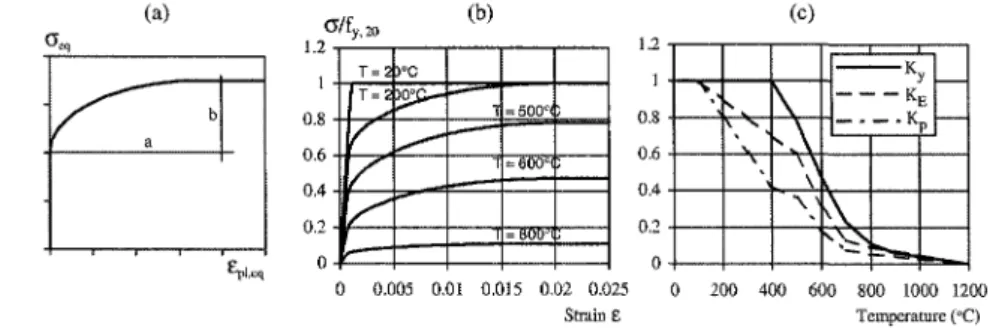
The elliptical law that is used for the isotropic hardening function is not exactly equal to the function defined as the stress-strain relationship at elevated temperatures in Eurocode 3 part 1.2 (Figure 4(b)). Eurocode 3 defines the relationship in the σ-ε plane, whereas the present law is defined in the σeq-εpl,eq plane (Figure 4(a)). The hardening function is defined here as:
The following equations are used to calculate the yield strength, the Young's modulus, the tangent modulus, and the proportional limit at elevated temperatures:
Figure 4. Elliptic hardening, σ-ε at elevated temperature and reduction coefficients for steel.
Concrete
It is essential to define a concrete model that is appropriate for modeling the experimentally observed behavior of concrete slabs exposed to fire. The model must encompass every aspect that really influences the behavior of the structure, either one way or two-way slabs, and be simple enough in order to allow simulations to be performed at a reasonable cost if the software is to be applied in civil engineering applications. The definition is based on the following considerations:
● Even if thermal gradients appear over the thickness, this does not generate any stress perpendicular to the plane of the shell and a plane stress model is still appropriate, as it is for shells at room temperature or under elevated uniform temperature.
● Representation of the elasticity of the material is a minimum requirement in any element if a stiffness matrix has to be built.
● Concrete is known to have a poor behavior when exposed to tension and this must be represented accurately. A simple Rankine tension cut off has been implemented here. Two points require further discussion.
(a) This criterion may be regarded as a crude representation of real concrete behavior especially in the tension-compression regime. It is considered to be acceptable for the usual building reinforced concrete slabs in which tension strength is not supposed to be provided by the concrete but, on the other hand, by steel rebars. It has to be realized that this criterion should be refined if the element must be used, for example, for the modeling of shear walls exposed to fire.
(b) It has been shown by comparison with experimental tests that laboratory results are better represented when a certain amount of tension strength is introduced in the model [16,17]. For practical design applications, it is recommended that zero be used for the tension strength, and this is also a justification why the simple Rankine criterion may be acceptable. The reasons for designing with a zero tension strength are:
■ In a real building, the slab is likely to be exposed to a history of various thermal and loading cycles before being exposed to fire.
These will have induced a significant amount of cracking in the structure, the level of which can hardly be estimated determinis-tically.
■ Shrinkage of concrete in the reinforced slab during the period that precedes the fire can also lead to tension stresses and hence cracking in the concrete.
■ If building structures were designed on the basis of 'a zero' tension strength at room temperature as a safe approximation, it would be even more unsafe to rely on tension strength of concrete at elevated temperatures to ensure the stability of a building. This is because tension strength in concrete decreases faster with increases in temperature than other material properties, such as compressive strength of concrete or yield strength in steel bars [18].
● Because of the transient nature of thermal strains in a concrete slab during a fire, several integration points in the structure usually see their situation changing from tension to compression and vice versa. It is thus essential that the closing of cracks be treated appropriately. This is the case if tension is treated in the frame of plasticity; when the equilibrium point goes back to compression strains after cracking in tension, a new elastic loading in compression can be undertaken.
● Because of the poor behavior of concrete in tension, tension forces must be supported in the finite element by the steel bars. Smeared layers of steel bars have been embedded in the finite element. These bars develop stiffness and stress only in the direction of their axis. In other words, only an elongation in the direction of their axis will produce a stress while an elongation perpendicular to the axis or a shear strain in the element does not produce any stress in the bars.
● It has been shown in experimental tests that the behavior of two-way slabs exposed to fire is predominantly influenced by the large deflections that arise [19,20]; the transmission of the applied loads changes from a bending mode at room temperature to a tension membrane mode during the fire. This mode of load transmission can only be activated if the large displacements are represented, and these large displacements are mainly produced by the thermal strains. It is therefore essential, if two-way slabs are to be modeled, that the thermal strains be taken into account. A hydrostatic isotropic thermal strain has been embedded in the concrete model. The recommendation of Eurocode 2 and Eurocode 3 give the nonlinear temperature dependency of the thermal strain for concrete and for steel. Of course, the thermal strain will also influence the displacements and the stress pattern in one-way slabs, but this is not as crucial as in two-way slabs.
● The amplitude of the displacements and the stress distribution will also be somewhat influenced by the stiffness of concrete in compression and this will decrease with temperature increase. It is therefore worthwhile to incorporate this temperature dependency and, hence, have a thermo-elastic behavior in compression. This may have a significant effect especially in continuous slabs, because the compression zone is the heated zone near the intermediate support and has much less effect in simply supported slabs, where the compression zone remains at rather low temperatures.
● For the same reason in continuous slabs, it may be worth limiting the amount of compression force that concrete is able to develop and, hence to introduce a limit surface bounding the elastic domain. Because this is one of the most widely used and tested surfaces, concrete is assumed here to be bounded by a von Mises surface. ● Concrete in compression -compression is known to have a better behavior than that predicted by the von Mises surface. This is true at room temperature and this effect is even more pronounced at elevated temperature [21]. The von Mises surface is considered as a sufficiently good approximation because, in the fire situation, even the central zone of a two-way slab is no longer exposed to a compression-compression situation; on the contrary, it is in a situation of tension-tension created by the membrane effect induced by large displacements. It has also to be considered that, among the various phenomena that have to be taken into account in the concrete model for the fire situation, crushing of concrete in compression is very low in the priority list. It would not however be a major difficulty to implement another failure surface, for example a Drücker- Prager surface, if the need arises in the future.
For reinforced concrete plates, to summarize, the contribution of concrete is taken into account by a temperature-dependent von Mises plane stress-associated plasticity model on which a Rankine tension cut off has been added in tension; isotropic thermal strain is also taken into account.
The evolution of the Young's modulus and the curve for isotropic hardening are chosen in order to match as closely as possible the recommendations of Eurocode 2 for the uniaxial stress-strain relationship of concrete. Equation (17) gives the hardening function that has been chosen:
ALGORITHMIC STRATEGY
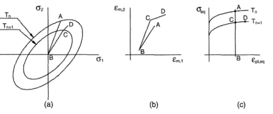
The equilibrium of an integration point of the structure, at the time 't' (step n), is represented by A in Figure 5. All the state variables (stresses, strains, displacements, temperatures, etc.) have been calculated in the previous step and the structure has reached its equilibrium state.
If the initial strain {εi} and the thermal strain {εth,n} are subtracted from the total strain {εtot,n}, the mechanical strain {εm,n} is obtained from:
When the temperature changes from Tn to Tn+1 , it is possible to determine the new von Mises surface, which
corresponds to the new hardening parameter (Figure 5(c)), assuming that the plastic strain is not affected by the variation of temperature, i.e., the plastic strain is not modified from the end of step n to the beginning of step n
+1.
In the algorithm used by SAFIR, it is assumed that the structure is 'locked' at the first iteration of each time step, i.e.,
Figure 5. First iteration of a time step in plastic behavior.
As the thermal strain is modified by the variation of temperature, the 'mechanical' strain changes accordingly:
It is now represented by point D in Figure 5. The segment A-D represents the increase of thermal strain from temperature Tn to Tn+1 As the thermal strain is hydrostatic, this part is inclined at 45° in Figure 5(b). For each
iteration, the calculation will start from the unloaded structure (point B). The strain increment to be applied from the unloaded state is given by:
The classic plasticity theory is applied at temperature Tn+1 in order to load the structure from point A to point D
(see Figure 5). The stress {σln+l} and the new tangent matrix [D1t,n+1] are computed. The return mapping
algorithm, and Euler backward algorithm for the integration of the plastic strain, established at ambient temperature, are used here.
Of course, the stresses obtained in the structure after the first iteration are not in equilibrium and they generate out of equilibrium forces in the structure which, using the new tangent stiffness matrix, allow the calculation of displacement increments and their corresponding strain increments {∆ε1-2}
At the next iteration, the strain increment to be applied from the unloaded state is:
In fact, in the calculations, the temperature does not vary during a time step. When the equilibrium is finally reached, if point D is outside the yield surface calculated at the beginning of the time step Tn+1, the hardening has
increased and this is taken into account by updating the plastic strain and the equivalent plastic strain of the yield surface.
NUMERICAL VALIDATION
Except when specified otherwise, all the data given in this section are consistent, i.e., they can be expressed in any system of units, provided that a single system is used for each example. Whether the data are expressedin the SI or in the British system of units does not matter, the numbers that form results will be the same, expressed in the relevant system.
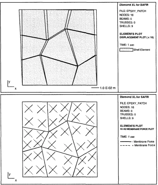
Patch Tests
It has been verified that the element passes the kinematic patch tests. In a simple structure that comprises internal nodes and at least one element of irregular shape, the displacements are prescribed on the borders of the structure in such a way that this should create a uniform situation inside the domain and it is verified whether this is really the case for the numerical solution. This has been done for the three constant membrane states (εxx = constant, εyy
= constant, and εxy = constant), as well as for the three constant bending states (χxx = constant, χyy = constant, and
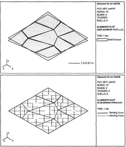
χxy = constant). Figure 6 shows the imposed kinematic constraint and the principal membrane forces for a
situation of uniform shear. Figure 7 shows the imposed kinematic constraint and the principal bending forces for a situation of uniform torsion.
Figure 7. Kinematic patch test in torsion.
The results presented in Figures 6 and 7 are for the first iteration of the analysis, i.e., for the solution in small displacements. When large displacements are taken into account in the subsequent iterations, the imposed displacement field at the boundary ceases to establish a uniform situation in the structure.
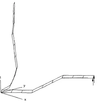
Response of an Elastic Z-shaped Cantilever at Room Temperature
The structure is a Z-shaped cantilever subjected to a transverse end load (Figure 8). The solution given in [22] is based on nine equal-sized elements. The structure is oriented at 45° from the x-z plane to activate all three translations and rotations in the element formulation.
The beam is divided into three equal parts (each part is meshed with three elements). The two parts parallel to the x-y plane have a length of 60 and a width of 20. The middle part (inclined) has also a length of 60 and an elevation of 30 in the z-direction; the width is 20. The thickness of the beam is 1.7.
All the six DOF are restrained at one end and two concentrated nodal forces are applied in the positive z-direction at the other end. The load is increased up to 4000 with a step of 10.
The material is elastic, the Young's modulus is equal to 2.0 x 10⁵ and the Poisson's ratio is equal to 0.3. This problem is solved at ambient temperature (20°C).
Figure 8. Initial geometry and deformed shape for a load of 4000.
Two calculations have been performed, the first one 'SAFIR 10' with a load increment of 10, to check that SAFIR gives the same continuous curve as the one given by NAFEMS (National Agency for Finite Element Method and Standards). The second one ('SAFIR 500') has a larger load increment (of 500) to check whether SAFIR is able to manage large load and/or displacement increments between each step. It can be seen in Figures 8 (displacements not amplified) and 9 that the element introduced in SAFIR gives good results in case of bending with large geometric nonlinear behavior. The results obtained for a load step of 500 ('SAFIR 500') are also very good even if the first point is a little bit too high compared to the two other curves. It has to be realized that a displacement of nearly 125 has been accommodated within one single step.
Figure 9. Load-displacement for the Z-shape.
Twisted Cantilever Beam at Room Temperature
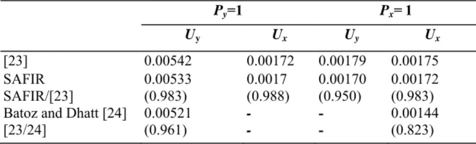
This example (see Figure 10) has been defined in [23] and, since 1985, is one of the most widely used benchmarks for testing the effects of warping in quadrilateral elements.
Whereas the length of the beam is 12 and the width of the section is 1.1, the test is usually run for two different thicknesses of the section, namely 0.32 and 0.0032 with a Young's modulus equal to 29 × 106 and a Poisson's ratio of 0.22. The concentrated forces are either applied in the X- (see Figure 10) or in the 7-direction.
The thickness of 0.32 is used to check the correctness of the formulation of the shell element and the thickness of 0.0032 is used to check the element against membrane locking. Tables 1 and 2 show the displacements obtained
at the loaded extremity of the beam for the crude mesh based on six finite elements as shown in Figure 10. Also mentioned in these tables are the results presented in [24]. Here again, in order to allow comparison for the benchmark example presented in small displacements, the results of SAFIR are those obtained after a single iteration. The differences between the exact solutions and the numerical simulations are in the range of 1-5%.
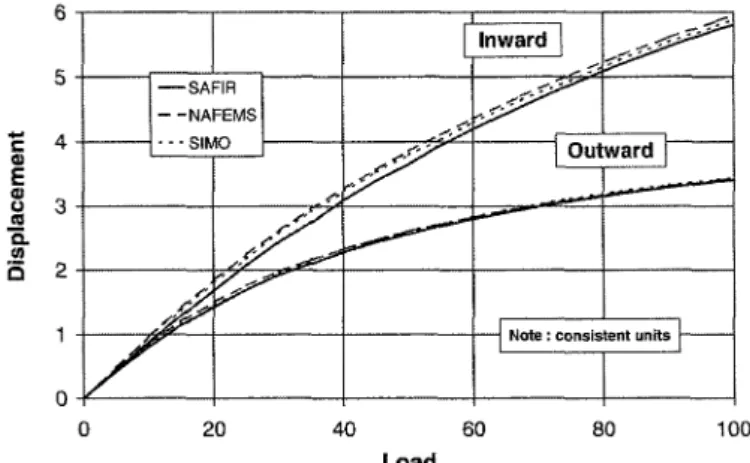
Elastic Hemispherical Shell at Room Temperature
A benchmark test that takes large displacements into account is shown in Figure 11. One-eighth of the sphere [22] has been meshed with 16 × 16 quadrilateral elements. The radius of the sphere is 10 and the thickness is equal to 0.04. The following symmetrical boundary conditions have been used:
Symmetry on the plane y = 0
Symmetry on the plane x = 0
Figure 10. Twisted cantilever beam.
Table 1. Results for the twisted cantilever beam (h=0.32).
Py=1 Px=1
Uy Ux Uy Ux
[23] 0.00542 0.00172 0.00179 0.00175
SAFIR 0.00533 0.0017 0.00170 0.00172
SAFIR/[23] (0.983) (0.988) (0.950) (0.983)
Batoz and Dhatt [24] 0.00521 - - 0.00144
Table 2. Results for the twisted cantilever beam (h = 0.0032). Py= 1 Pχ=1 Uy Ux Uy Ux [23] 5316 1878 1878 1296 SAFIR 5226 1858 1858 1281 SAFIR/[23] (0.983) (0.989) (0.989) (0.988) [24] 5163 - - 1251 [23/24] (0.971) - - (0.965)
Figure 11. Hemispherical shell.
To prevent the rigid body mode in the z-direction, the point, A, was restrained to have x-translations only, i.e., Uz
= 0. Inward and outward diametrical point loads were applied as concentrated nodal forces at locations, A and B,
respectively. The loads are increased up to a maximum of 100. The material is elastic, the Young's modulus is equal to 6.825 × 10⁷ and Poisson's ratio is equal to 0.3. This problem is solved at ambient temperature (20°C). This problem tests the performance of the geometric nonlinear formulation for shells under membrane, bending and twisting actions. It can be seen (Figure 12) that SAFIR gives good results in case of large rotations and deflections. For the inward displacement, SAFIR is stiffer than the results obtained by NAFEMS [22], but the results are close to the ones obtained by Simo. This test confirms that there is no membrane locking in the element.
Figure 13. Lee's frame.
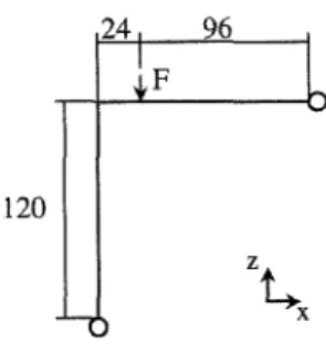
Lee's Frame at Elevated Temperatures
This example has been chosen because it is almost the only benchmark test available to check the accuracy of the finite element software under fire conditions. It has initially been published by Franssen et al. [25] and has shown that five different computer codes using beam finite elements and under increasing temperature give similar results. The structure is shown in Figure 13. The vertical and the horizontal members have a length of 120. Two meshes have been used to check the behavior in case of bending (shell elements in the x-y plane for the horizontal member and in the y-z plane for the vertical member) and in case of 'membrane bending' (all the shell elements are in the x-z plane).
At the ends of the frame, the following displacements have been fixed:
The cross section of the beam is equal to 6 and the inertia is equal to 2. Eight-point Gauss integration points are used through the thickness of the elements. A vertical load of 0.2 is applied to the structure at a distance of 96 from the right top edge. The temperature is uniform in the structure and it is increased until collapse. The Young's modulus is equal to 720, the yield stress is equal to 3.0 and Poisson's ratio is equal to 0.3. The material properties decrease with temperature according to ENV 1993-1-2.
Figure 14. Horizontal displacement vs temperature.
The results under fire conditions have been compared with the same finite element software as have been used for the comparison at room temperature [25]. It can be seen (Figure 14) that in case of bending (SAFIR-Bending) the shell element of SAFIR gives results close to the beam element. In the case of 'membrane bending' (SAFIR-Membrane-Bending) the result is a little bit higher with the shell element than the results provided by the other elements. It has to be highlighted that the integration of plasticity over the depth of the beam is performed only at four integration points (two in each of the two elements used in the mesh).
This example shows that the new element correctly takes into account the thermal elongation and the stress-strain relationship according to Eurocode 3.
H-rolled Profile
Calculations have been performed on an S355 HE 300 AA+. The length of the short beam is 1 m. The boundary conditions are defined as follows:
First end: All the nodes are locked on the longitudinal displacement and all the rotations. The lateral
displacement is locked at all the nodes on the web and all the displacements are locked at the point in the middle of the web.
Second end: All the nodes have an imposed longitudinal displacement in compression and all the rotations are locked. The lateral displacement is locked at all the nodes on the web and all the displacements are locked at the point in the middle of the web.
An initial sinusoidal imperfection (maximal magnitude = 10 mm) is imposed on the web and the flanges. The temperature is uniform in the structure and it is increased at the same time as the displacement is increased. In this structure, the stress is a function of the imposed longitudinal displacement and of the thermal strain (restrained). As the temperature and displacement are increased at the same time, the maximum reaction force occurs when the temperature of the structure reaches 42° C and the longitudinal displacement is equal to 1.8 mm. The ratio between the maximum load applied to the structure and the theoretical crushing compressive load is equal to 0.92. As the calculation has been performed with imposed displacement, post-critical behavior can be studied easily. Figure 15 shows the deformation of the beam when the simulation was stopped (displacements not amplified). It can be seen that large deformations have been obtained in the middle of the beam. The temperature in the structure at this moment is 1000°C and the imposed shortening is equal to 81 mm. As can be seen in Figure 15, the local buckling obtained by calculation has the same shape as the one obtained during an experimental test at Cardington.
Figure 15. Deformed profile at the last converged step and local buckling of a structure exposed to fire
(Cardington). (The color version of this figure is available on-line.)
Concrete Slab
The performance of the shell element with concrete material properties is compared with experimental fire tests of two-way concrete slabs conducted at a fire resistance furnace in New Zealand by Lim and Wade [26]. Six two-way slabs, comprising reinforced concrete flat slabs and composite steel-concrete slabs were tested. They were simply supported at all four edges and were axially unrestrained. The slabs were loaded with a live load of 3.0 kPa while being exposed to the ISO fire from below for 3 h. All the slabs supported the loads for the entire fire duration without collapse, despite suffering large midspan vertical deflections (up to 270 mm).
The modeling of one of the tested slabs is presented here and is based on the work by Lim and Wade [16]. The geometry and material properties of the finite element model are shown in Table 3 and are based on the tested slab. The reinforcing steel and concrete material properties used in the model were based on the Eurocode 2 part 1.2. Different values of concrete tensile strength were used in the analyses, ranging from OMPa (fully cracked) to 3.0 MPa (0.5 √fc).
Figure 16 compares the experimental results with the SAFIR predictions. The SAFIR analysis was conducted with different values of concrete tensile strength, 0, 1.5, and 3 MPa respectively. The displacement transducer malfunctioned after 140 min and the deflection of the slab had to be measured manually at the end of the test. The graph (Figure 16) shows that with zero tensile strength in the concrete, SAFIR predicted slightly larger deflections than the experimental results throughout the entire fire duration. Nevertheless, the deflection trend predicted by SAFIR was very similar to the experimental results, showing a high deflection rate during the first 30 min, followed by a gradual deflection rate up to 150 min and finally increasing again from 150 to 180 min. The SAFIR analysis stopped at 189 min when the reinforcing steel at midspan ruptured. The larger deflections predicted by SAFIR, with zero concrete tensile strength, were attributed to the slab being fully cracked and being more flexible than the tested slab. The high fire resistance of this lightly reinforced slab was attributed to the loads being resisted by tensile membrane action instead of bending action.
Table 3. Properties of the tested slab.
Clear span in long direction, Ly 4.16m
Clear span in short direction, Lx 3.16m
Slab thickness, h 100 mm
Concrete compressive strength, f'c 36 MPa
Concrete cover, cc 25 mm
Reinforcing mesh 198mm2/m in both directions
(ø8.7@300mm) Yield strength (ambient temperature), fy,0 565 MPa
Self weight 2.4 kPa
Live load 3.0 kPa
Figure 16. Comparison of the experimental results with the SAFIR analyses.
With a concrete tensile strength of 1.5MPa, SAFIR showed good agreement with the tested slab throughout the entire fire duration. SAFIR predicted low deflections before the fire started, when the concrete had no cracks, followed by thermal bowing deflections during the initial stages of the fire, leading to final failure of the slab at 192 min.
With a concrete tensile strength of 3 MPa, the deflections predicted by SAFIR showed good agreement with the experimental test results during the first 100 min. Beyond that, the deflections started to diverge as the predicted
deflections asymptote to -0.20 m. It shows that the concrete model is very ductile when high values of concrete tensile strength are used, as the concrete does not crack and deflect sufficiently at the later stages of the fire. Figure 17 shows the distribution of the principal membrane forces in 1/4 of the slab. The membrane forces are plotted at the surface integration points of the slabs. The dark lines represent compressive forces while the light lines represent tension forces. Figure 17 shows that a compression ring has formed at the outer edges of the slab, surrounding a tension field at the midspan region. These in-plane membrane forces are a result of the deflected shape of the slab. The tension field at midspan is due to the large deflections while the compression ring at the outer edges is a result of the resistance of the outer edges against the inward contraction of the slab caused by the sagging midspan deflections. The slab resists the loads as a membrane and will fail only when the steel at midspan ruptures or when the concrete at the edges is crushed. These tensile membrane forces, instead of bending action, explain the high fire resistance reached by the slab. The failure predicted by SAFIR corresponds to the fracture of the reinforcing steel mesh. The slab will fail, as the tensile forces cannot be sustained by the structure any more. These phenomena are in good agreement with the ones observed during the fire test. In this example, and in others that are presented in [16], the modeling by SAFIR generally agrees well with the experimental results, which tends to prove that the element and the utilized material models are able to represent the behavior of reinforced concrete slabs undergoing very large transverse displacements in a fire.
Figure 17. Distribution of principal membrane forces in the slab at failure.
CONCLUSIONS
After a brief description of the quadrangular shell element introduced in SAFIR and the material properties that are used with this element, some calculations have been performed to validate this element.
The element passes the kinematic patch tests. The z-shape and the twisted cantilevers show that the element can be subjected to large geometric nonlinear behavior. The hemispherical shell and the twisted beam (thickness of 0.0032) show that this element is not subjected to membrane locking.
Lee's frame at elevated temperatures demonstrates that the material properties from Eurocode 3 have
successfully been introduced in SAFIR in the case of a plane stress relationship and that the thermal elongation is accurately taken into account.
The concrete model could be refined, especially for members where either the tension strength or the crushing strength plays a crucial role such as, for example, in shear walls.
Some comparisons with experimental tests indicate the validity of the approach for reinforced concrete slabs exposed to large transverse displacements.
ACKNOWLEDGMENTS
This work was sponsored by the European Commission (Marie Curie Fellowship, contract number:
ERBFMBICT983336). REFERENCES
1. FINELG - Nonlinear Finite Element Analysis Program, User's Manual Version 6.2, Feb. 1984.
2. Jetteur, Ph., "Non-Linear Shell Elements Based on Marguerre Theory," IREM Internal Report 85/5, Swiss Federal Institute of Technology, Lausanne, Switzerland, Dec. 1985.
3. Jetteur, Ph., "A Shallow Shell Element with In-plane Rotational Degrees of Freedom," IREM Internal Report 86/3, Swiss Federal Institute of Technology, Lausanne, Switzerland, March 1986.
4. Jetteur, Ph., "Improvement of the Quadrangular "JET" Shell Element for a Particular Class of Shell Problems," IREM Internal Report 87/1, Swiss Federal Institute of Technology, Lausanne, Switzerland, Feb. 1987.
5. Jaamei, S., Frey, F. and Jetteur, Ph., "Element Fini de Coque Mince Non-Lineaire a Six Degres de Liberté par Noeud," IREM Internal Report 87/10, Swiss Federal Institute of Technology, Lausanne, Switzerland, Nov. 1987.
6. Allman, D.J., "A Compatible Triangular Element Including Vertex Rotations for Plane Elastic Analysis," Comput. Struct., Vol. 19, 1984, pp. 1-8.
7. Jaamei, S., ""JET" Thin Shell Finite Element with Drilling Rotations," IREM Internal Report 88/7, Swiss Federal Institute of Technology, Lausanne, Switzerland, July 1988.
8. Idelsohn, S., "Analyses Statique et Dynamique des Coques par la Méthode des Elements Finis," PhD Thesis, Liege, 1974.
9. Batoz, J.L., Bathe K.J. and Ho, L.W., "A Study of Three Node Triangular Plate Bending Elements," Int. J. Num. Meth. Eng., Vol. 15, 1980, pp. 1771-1812.
10. Batoz, J.L., "An Explicit Formulation for an Efficient Triangular Plate Bending Element," Int. J. Num. Meth. Eng., Vol. 18, 1982, pp. 1077-1089.
11. Batoz, J.L. and Ben Tahar, M„ Evaluation of a New Quadrangular Thin Plate Bending Element, Int. J. Num. Meth. Eng., Vol. 18, 1982, pp. 1655-16.
12. Jetteur, P. and Frey, F., "A Four Node Marguerre Elemeent for Non-linear Shell Analysis," Engineering Computations, Vol. 3, No. 4, Dec, 1986, pp. 276-282.
13. Jaamei, S., Frey F. and Jetteur, P., "Nonlinear Thin Shell Finite Element with Six Degrees of Freedom per Node," Computer Methods in Applied Mechanics and Engineering, Vol. 75, No. 1-3, Oct, 1989, pp. 251-266.
14. Carpenter, N., Stolarsky, H. and Belytschko, T., "Flat Triangular Shell Element with Improved Membrane Interpolation," Communications in Applied Numerical Methods, Vol. 1, No. 4, 1985, pp. 161-168.
15. Taylor, R. and Simo, J.C., "Bending and Membrane Elements for Analysis of Thick and Thin Shell," In: Proceedings NUMETA 1985 Conference Swansea, 1985, pp. 587-591.
16. Lim, L., "Membrane Action in Fire Exposed Concrete Floor Systems," PhD Thesis, Department of Civil Engineering, University of Canterbury, New Zealand, 2003.
17. Lim, L., Buchanan, A. and Moss, P., "Behaviour of Simply-Supported Two-way Reinforced Concrete Slabs in Fire," In: Proc. Designing Structures for Fire, SFPE, 2003, pp. 227-236.
18. Schneider, U., "Properties of Materials at High Temperatures. Concrete," Dpt. of Civil Engineering, Gesamthochschule Kassel, 1985. 19. Gillie, M., Usmani A.S. and Rotter, J.M., "A Structural Analysis of the Cardington British Steel Corner Test," J. Constr. Steel Research, Vol. 58, 2002, pp. 427-442.
20. Usmani, A. "Understanding the Response of Composite Structures to Fire," Proc. NASCC, Section D5, A.I.S.C. Inc., 2003. 21. Ehm, C, "Versuche zür Festichkeit und Verformung von Beton unter Zweiaxialer Beanspruchung und höhen Temperaturen," PhD Thesis, Inst. Fr Baustoffe, Massivbau and Brandschutz, Technischen Universität Braunschweig, 1986.
22. Prinja, N.K. and Clegg, R.A., "Assembly Benchmark Tests for 3-D Beams and Shells Exhibiting Geometric Non-Linear Behaviour," NAFEMS 1993, Ref.: R0029.
23. MacNeal, R.J. and Harder, R.L., "A Proposed Standard Set of Problems to Test Finite Element Accuracy," Finite Elements in Analysis and Design, Vol. 1, 1985, pp. 3-20.
24. Batoz, J.L and Dhatt, G., Modélisation des structures par elements finis, Vol. 3, Coques, Henries, Paris, 1990.
25. Franssen, J.M., Schleich, J.b., Cajot, L.G., Talamona, D., Zhao, B., Twilt, L. and Both, K., "A Comparison between Five Structural Fire Codes Applied to Steel Elements," In: IAFSS, Fire Safety Science, Proceedings of the Fourth International Symposium, 1984.
26. Lim, L. and Wade, C, "Experimental Fire Tests of Two-Way Concrete Slabs," Fire Engineering Research Report 02/12, Department of Civil Engineering, University of Canterbury, New Zealand, 2002.