UNIVERSITÉ DE MONTRÉAL
DISCOVERY AND CORRECTION OF SPATIAL NON-UNIFORMITY IN OPTICAL FIBERS: TOWARDS THE FABRICATION OF PERFECT ULTRA-LONG FIBER BRAGG
GRATINGS FOR APPLICATIONS IN NON-LINEAR OPTICS
SÉBASTIEN LORANGER
DÉPARTEMENT DE GÉNIE PHYSIQUE ÉCOLE POLYTECHNIQUE DE MONTRÉAL
THÈSE PRÉSENTÉE EN VUE DE L’OBTENTION DU DIPLÔME DE PHILOSOPHIAE DOCTOR
(GÉNIE PHYSIQUE) JANVIER 2018
UNIVERSITÉ DE MONTRÉAL
ÉCOLE POLYTECHNIQUE DE MONTRÉAL
Cette thèse intitulée:
DISCOVERY AND CORRECTION OF SPATIAL NON-UNIFORMITY IN OPTICAL FIBERS: TOWARDS THE FABRICATION OF PERFECT ULTRA-LONG FIBER BRAGG
GRATINGS FOR APPLICATIONS IN NON-LINEAR OPTICS
présentée par : LORANGER Sébastien
en vue de l’obtention du diplôme de : Philosophiae doctor a été dûment acceptée par le jury d’examen constitué de :
M. GODBOUT Nicolas, Ph. D., président
M. KASHYAP Raman, Ph. D., membre et directeur de recherche M. LEBLOND Frédéric, Ph. D., membre
DEDICATION
To my mother, Claire, who would have been proud to see me finish this PhD.
ACKNOWLEDGEMENT
I would like to give a very special thanks to Raman, who has been a great mentor and has led me into this great adventure of research and science. Thanks to him, I have high hopes for my future career.
I would also like to give a special thanks to my close friend and colleague Victor, with whom I have shared most of my years here at Polytechnique. Our work together has been very fun and instructive and I hope that our paths will cross on many future occasions!
I would like to thank my friends and colleagues Jean-Sébastien Boisvert, Jérome Lapointe, François Parent, Mathieu Gagné, Elton Soares, Mamoun Wahbeh, Amir Tehranchi, Frédéric Monet, Antoine Drouin and Meenu Ahlawat. Working with all of those friends has made this PhD very interesting, fun and instructive.
I wish to give a special thanks to our devoted technicians Jules Gauthier, Steve Dube, Jean-Paul Lévesque, Mikael Leduc, Jean-Sébastien Décarie and Traian Antonescu, without which none of this work would have been possible.
I would also thank the Vanier Canada Graduate Scholarship and the Natural Sciences and Engineering Research Council of Canada for the funding and support during my PhD.
Finally, a special thanks to my family and friends who have supported me during those long studies, especially my dad, André, who has always been there for me.
RÉSUMÉ
Les réseaux de Bragg (FBGs) sont des dispositifs tout-fibre communs en photonique et très utilisés en télécommunications comme filtres, réflecteurs sélectifs, compensateurs de dispersions et bien plus. Le sujet de cette thèse concerne les réseaux de Bragg ultra-longs, soit plus longs que la longueur typique des masques de phase (>20 cm). Les FBG ultra-longs ont la particularité d’avoir une très petite bande passante, un long temps de vie pour les modes de cavités distribués (DFB, cavité dont le champ des modes est distribué sur toute la longueur du réseau) et un grand chirp pour des FBG chirpé. Cette thèse étudie les cavités DFB ultra-longues à saut de phase, idéalement de π. Celles-ci comportent un seul mode de cavité à très haut facteur de qualité qui peut être utilisé comme laser lorsqu’un gain est présent. De tels lasers ont la propriété d’être monomode avec une largeur d’émission très fine en fréquence. Lorsqu’un gain non linéaire est présent, tel que du Brillouin ou Raman stimulé, ce qui est possible avec des FBGs ultra-longs, de tels lasers n’ont pas de restriction bande de longueurs d’onde, ce qui n’est pas le cas du gain des terres rares. En d’autres mots, ils peuvent être opérés à n’importe quelle longueur d’onde.
Ces dispositifs ultra-longs spécialisés ont toujours été très difficiles à produire. Même avec les meilleurs systèmes, la reproductibilité de fabrication de FBGs ultra-longs de haute qualité était absente. À cause de cela, de tels dispositifs n’ont jamais été développés pour des applications commerciales. Cette thèse étudie les difficultés d’écriture de FBGs ultra-longs et démontre des solutions permettant une reproductibilité de haute qualité. La méthode d’écriture utilisée et étudiée au long de cette thèse est l’écriture en continu par modulateur électro-optique avec interféromètre de Talbot. La principale difficulté trouvée dans l’écriture de FBGs ultra-longs est la haute non-uniformité dans toutes les fibres optiques, une caractéristique difficile à mesuré et hautement néfaste pour les FBG ultra-longs. La solution proposée : faire une correction de phase pendant l’écriture afin de permettre un réseau parfait dans toute fibre. La thèse présente 4 articles montrant les limitations et solutions de la fabrication de FBGs ultra-longs ainsi que l’opération de laser DFB à fibre par gain Brillouin et Raman dans de tels FBGs.
La thèse montre, dans la première publication, l’avantage de FBGs ultra-longs en démontrant un laser DFB avec un gain Brillouin dans de la fibre standard (SMF-28), au lieu de fibre hautement non linéaire typiquement utilisé pour de tels lasers. En effet, en utilisant des FBGs ultra-longs, le seuil laser peut être réduit grandement grâce au très long temps de vie des photons dans la cavité
monomode, permettant ainsi l’utilisation de fibres faiblement non linéaires d’être utilisées. Une nouvelle technique est aussi démontrée afin d’écrire des sauts de phase reproductible avec une écriture en continu utilisant des modulateurs électro-optiques : en générant un saut temporaire en longueur d’onde de Bragg écrite. Cette technique résout un des problèmes du manque de rétroaction sur les modulateurs de phase, un problème décrit dans la thèse.
Bien que les FBGs DFB ultra-longs ont été démontrés dans la SMF-28, la production reproductible de tels réseaux dans d’autres types de fibres se montrait impossible. Cette thèse identifie le problème: la non-uniformité des fibres optiques. Une nouvelle méthode de caractérisation est décrite afin de mesurer cette non-uniformité, un sujet du second article présenté dans cette thèse. La méthode comprend l’écriture de FBGs sondes à différentes longueurs d’onde dans la même région d’intérêt de la fibre, puis l’utilisation de réflectométrie optique dans le domaine fréquentiel afin de mesurer la longueur d’onde de Bragg vs la position. Étant donné que tous les paramètres d’écritures sont bien contrôlés et que les fluctuations aléatoires dues à l’environnement sont moyennées par plusieurs FBGs, la déviation de longueur d’onde de Bragg observée est une mesure directe de la variation de l’indice de réfraction effective du mode guidé.
Une méthode de correction est alors proposée et démontrée afin de corriger cette non-uniformité et ainsi écrire des FBGs ultra-longs de façon reproductible. Cela est présenté dans le 3e article, où les résultats de FBGs produits sont comparés avant et après la correction. La méthode consiste à utiliser la mesure de déviation de longueur d’onde de Bragg afin d’écrire un FBG final où la phase est compensée selon cette mesure. La méthode s’est montré un grand succès.
Une fois qu’une méthode de production reproductible a été démontrée, une vaste étude de lasers DFB à fibre utilisant le gain Raman a été menée, soit le sujet du 4e article décrit dans la thèse. D’abord, une nouvelle méthode de simulation a été développée afin de permettre une résolution plus rapide des équations de modes-couplés. Une étude détaillée des paramètres des FBGs DFB a été menée et ces dispositifs ont été optimisés dans les conditions idéales. La simulation a été comparée avec des dispositifs expérimentaux, ce qui a mené à des conclusions intéressantes. Bien que de tels lasers DFB peuvent être très efficaces avec des seuils lasers très faibles, ils sont limités par l’apparition d’un gradient thermique due au chauffage du cœur de la fibre par la présente des champs internes de haute intensité. Des solutions sont proposées dans la thèse afin d’adresser le problème, telles que le contrôle dynamique du saut de phase pendant l’opération.
ABSTRACT
Fiber Bragg gratings (FBGs) are common all-fiber devices in photonics and have been widely used in telecommunications as filter, selective reflectors, dispersion compensators and more. The subject of this thesis is specialised Ultra-long FBGs, which are defined as longer then the typical length of a phase mask ( >20 cm). Ultra-long FBGs have the particularity of having very narrow bandwidth, long lifetime for distributed feedback (DFB) cavity modes and high chirp for chirped FBGs. A DFB cavity is a single-longitudinal-mode long cavity, as the photon is trapped along the entire length of the FBG. This thesis studies ultra-long DFB cavities known as “phase-shifted” or “π-shifted” and have a single phase defect inside the FBG to create the high Q cavity mode, which can then be used as a laser if an active gain medium is present. Such lasers would have the property of narrow linewidth single-frequency operation. When used with non-linear gain, such as Stimulated Raman or Brillouin gain, which can be done with ultra-long FBGs, those lasers have no specific band of operation restriction, contrary to rare-earth gain. In other words, they can be operated at any wavelength.
Those specialised ultra-long FBG devices have long been difficult to produce. Even with the best systems, reproducibility of high quality ultra-long FBGs has always been absent. Because of this, such device was never fully developed for commercial applications. This thesis studies the difficulties of ultra-long FBG writing and demonstrates solution for reproducible high-quality fabrication. Stimulated Brillouin and Raman scattering gain phase-shifted DBF ultra-long FBGs are then modeled, optimized and tested. The writing method is continuous writing using an electro-optic modulator driven Talbot interferometer. The main difficulty found in ultra-long FBG writing, is high non-uniformity found in all optical fibers, a characteristic difficult to measure and very detrimental for ultra-long FBGs. A solution was proposed for this: make a phase correction during writing to allow perfect FBGs in any fibers. The thesis presents 4 articles relating ultra-long FBG fabrication limitations and solutions as well as Brillouin and Raman DFB fiber laser operation in ultra-long FBGs.
The thesis shows, in the first publication, the advantage of ultra-long FBG by DFB lasers using non-linear gain (Stimulated Brillouin Scattering) in standard fiber (SMF-28), instead of typical highly non-linear fibers. Indeed, by using ultra-long FBGs, the lasing threshold can be significantly reduced thanks to the very long lifetime of photon in the long single-mode cavity, therefore
allowing low-non-linear fibers to be used. A new technique is also shown to ensure reproducible phase-shift with a modulator-based continuous writing system: by generating a temporary shift in written Bragg wavelength. This technique solves the issue of lack of feedback on modulators, a problem described in this Thesis.
Although long DFB FBG were demonstrated in SMF-28, reproducible production of ultra-long FBGs in other types of fiber was proven impossible, as stated above. This thesis identifies the issue: uniformity of fibers. A new characterisation method is described to measure this non-uniformity, a subject of the second paper described in the thesis. This method involves writing weak probe gratings at different wavelengths in the same length of interest of fiber, and then using optical frequency domain reflectometry to measure the Bragg wavelength vs position. As all writing parameters are well controlled, and environmental random fluctuation are averaged out by multiple probe FBGs, the observed Bragg wavelength deviation is directly related to a variation in the effective refractive index.
A correction method is then proposed and demonstrated to correct for this fiber non-uniformity and therefore write ultra-long FBGs in a reproducible way. This was demonstrated in a third paper, where production results are compared before and after correction with dramatic effect. The method consists in using the measured Bragg wavelength deviation from probe FBGs to write a final phase compensated FBG. The method proved very successful.
Once a reproducible production method was demonstrated, a vast study on DFB lasers using Raman gain was conducted, the subject of the 4th paper described in the thesis. First, a new simulation method was developed to allow a much faster solving of the couple-mode equation, compared to previous work on the subject. A detailed study on all parameters of ultra-long DFB FBG was undertaken and such devices were optimized in the ideal conditions. The simulation was compared with experimental data, which led to interesting conclusions. Although such DFB lasers could potentially be very efficient with low threshold, they are limited by non-linear thermal gradient due to heating from the high internal fields. Solutions are proposed in the thesis to address this, such as dynamically control the phase shift through heating or cooling, during laser operation.
TABLE OF CONTENT
DEDICATION ... III ACKNOWLEDGEMENT ... IV RÉSUMÉ ... V ABSTRACT ...VII TABLE OF CONTENT ... IX LIST OF TABLE ... XIII LIST OF FIGURES ... XIV LIST ACRONYMS AND ABBREVIATIONS ... XXI LIST OF APPENDIX ... XXIICHAPTER 1 INTRODUCTION ... 1
1.1 The Motivation and problem ... 3
1.2 Objectives ... 5
1.3 Organisation of thesis ... 6
CHAPTER 2 LITERATURE REVIEW ... 8
2.1 Modeling of fiber Bragg gratings ... 8
2.1.1 Theory of fiber Bragg gratings ... 8
2.1.2 Simulation techniques for non-uniform FBG ... 13
2.2 FBG writing techniques ... 17
2.2.1 Photosensitivity of glass ... 17
2.2.2 Laser sources for FBG fabrication ... 18
2.2.3 Writing techniques for short FBGs ... 19
2.2.4 Unlimited length FBG writing techniques ... 22
2.2.6 Optical Fourier domain reflectometry (OFDR) as characterisation tool ... 28
2.3 Specialised applications ... 29
2.3.1 Chirped fiber Bragg gratings ... 29
2.3.2 Superimposed gratings Delay enhancement ... 30
2.3.3 Optical scatter enhancement ... 31
2.4 Distributed feedback lasers ... 33
2.4.1 Theory of distributed feedback fiber Bragg gratings ... 33
2.4.2 Rare-earth medium DFB lasers ... 37
2.4.3 Raman and Brillouin gain DFB lasers ... 38
CHAPTER 3 GENERAL METHODOLOGY AND ORGANISATION ... 42
3.1 Methodology of the overall research ... 42
3.1.1 Design and simulation ... 42
3.1.2 Fiber Bragg grating writing system ... 45
3.1.3 Characterisation ... 49
3.1.4 DFB Laser operation ... 51
3.2 Organisation of the articles ... 53
CHAPTER 4 ARTICLE 1: STIMULATED BRILLOUIN SCATTERING IN ULTRA-LONG DISTRIBUTED FEEDBACK BRAGG GRATINGS IN STANDARD OPTICAL FIBER ... 55
4.1 Introduction ... 55
4.2 Method ... 56
4.3 Results and discussion ... 59
4.4 Conclusion ... 63
4.5 Acknowledgement ... 64
CHAPTER 5 ARTICLE 2: ARE OPTICAL FIBERS REALLY UNIFORM? MEASUREMENT OF REFRACTIVE INDEX ON A CENTIMETER SCALE ... 65
5.1 Introduction ... 65
5.2 Method ... 66
5.3 Results and discussion ... 68
5.4 Conclusion ... 73
5.5 Funding ... 73
CHAPTER 6 ARTICLE 3: REPRODUCIBLE ULTRA-LONG FBGS IN PHASE CORRECTED NON-UNIFORM FIBERS ... 74
6.1 Introduction ... 74 6.2 Method ... 76 6.3 Results ... 77 6.4 Discussion ... 81 6.5 Conclusion ... 82 6.6 Acknowledgement ... 82
CHAPTER 7 ARTICLE 4: OPTIMIZATION AND REALIZATION OF PHASE-SHIFTED DISTRIBUTED FEEDBACK FIBER BRAGG GRATING RAMAN LASERS ... 83
7.1 Introduction ... 83
7.2 Theory and simulation of ideal PS-DFB-FBGs ... 85
7.2.1 Simulation method ... 85
7.2.2 Optimization results of ideal PS-DFB-FBGs ... 87
7.3 Fabrication and characterization ... 91
7.4 Conclusion ... 96
7.5 Acknowledgement ... 97
CHAPTER 8 GENERAL DISCUSSION ... 98
8.1 Optimizing ultra-long FBG writing ... 98
CHAPTER 9 CONCLUSION AND RECOMMENDATIONS ... 115 REFERENCES ... 119 APPENDIX ... 129
LIST OF TABLE
Table 8.1: Summary of all issues found for continuous writing and their found/proposed solutions. The defects formed are (a) phase-shifts, (b) high frequency phase noise and (c) non-linear chirp (low frequency phase variation) and (d) represent limitations of the system. ... 100
LIST OF FIGURES
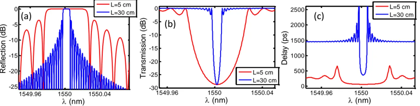
Figure 1.1: Hill et al.’s experiment discovering photosensitivity and how to make FBGs using an Ar-ion laser. A Fresnel reflection caused a standing wave in a Ge-doped silica fiber, which in turn wrote a permanent grating in the fiber through photosensitivity. ... 1 Figure 2.1: Schematic representation of a uniform FBG for (a) perfect visibility (v = 1) and (b) reduced visibility (v ~ 0.5) ... 9 Figure 2.2: Example of FBG (a) reflection, (b) transmission and (c) group delay of reflection spectra as calculated by the transfer-matrix method (section 2.1.2). A typical 5-cm short FBG is compared with an ultra-long 30-cm FBG for the same strength (κacL = 4). ... 12
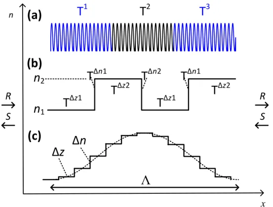
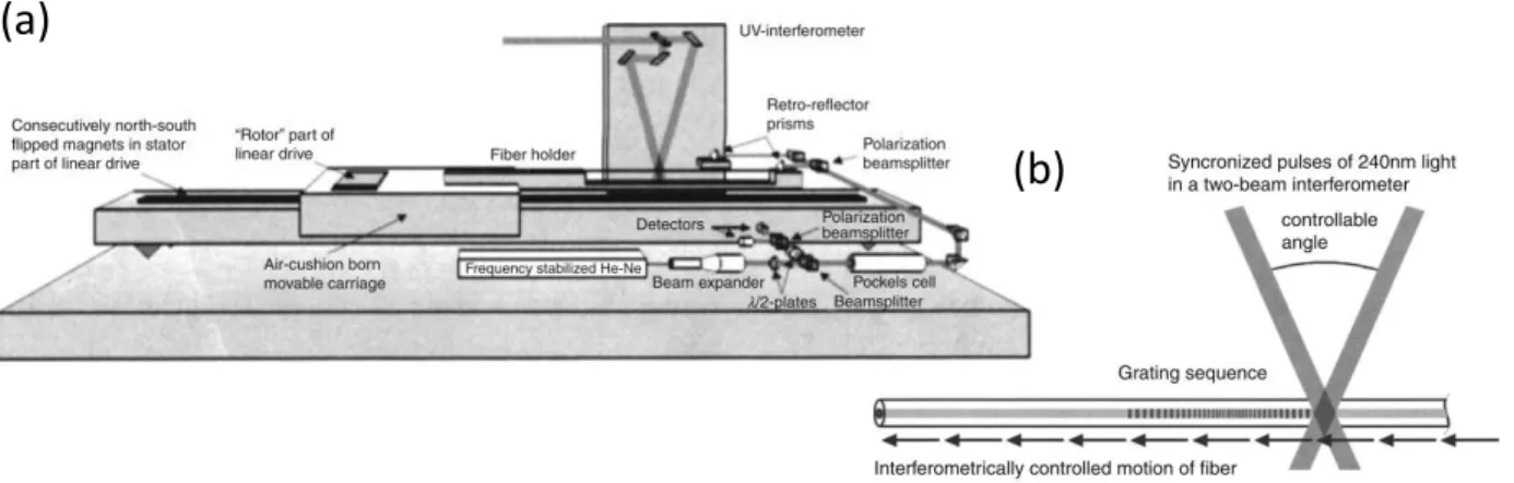
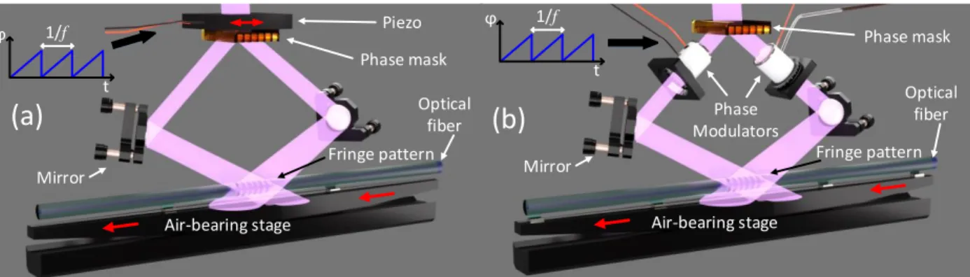
Figure 2.3: Schematic representation of a uniform FBG Δz section represented by a single matrix, with an integer number of periods. ... 14 Figure 2.4: Schematic representation of the 3 simulation techniques for simulating a FBG: (a) transfer matrix method (TMM), (b) thin-film method and (c) Rouard’s method. ... 15 Figure 2.5: Behind the mask technique. The phase mask used as a scanned interferometer. The quality of the grating is dependent on the uniformity of the phase mask. [15] © Elsevier 2010, reproduced with permission. ... 20 Figure 2.6: Tunable interferometer writing techniques: (a) Talbot interferometer using mirrors and (b) using a silica block and (c) Lloyd interferometer using a fold mirror and (d) a prism. [15] © Elsevier 2010, reproduced with permission. ... 21 Figure 2.7: Point-by-point inscription using (a) an amplitude mask with UV pulses and (b) using no mask with a fs infrared. When no mask is present, the head must be adjusted according to the exact core position along the fiber. ... 23 Figure 2.8: The multiple printing in fiber (MPF) technique where multiple FBGs are stitched together to conserve phase. [15] © Elsevier 2010, reproduced with permission. ... 23 Figure 2.9:Continuous writing scheme for ultra-long FBG using a Talbot interferometer. (a) A scanning phase mask or (b) phase modulators are required to move the fringe pattern synchronously with the fiber. ... 24
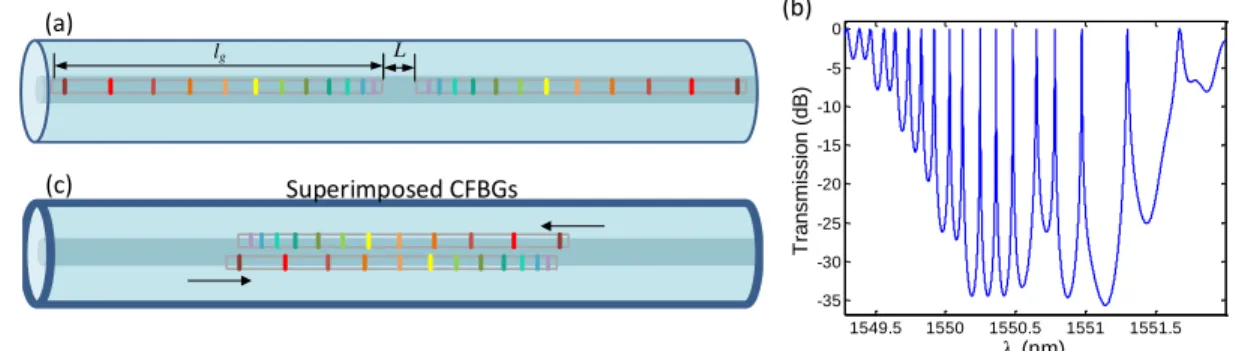
Figure 2.10: Schematic description of the tunability (𝑣𝑓𝑟𝑖𝑛𝑔𝑒 ≠ 𝑣𝑓𝑖𝑏𝑒𝑟) of continuous writing. (a) Ideal case of infinite tunability where a half-period or less is illuminated. (b) Practical case where tunability is limited by spot size where a de-synchronised fringe pattern vs fiber will erase the written FBG. ... 26 Figure 2.11: Optical circuit of an OFDR system. ... 29 Figure 2.12: (a) Fabry-Perot structure constructed with near-by CFBGs as proposed by Dong et al. as a tunable FSR cavity and (b) its corresponding simulation with L=1 mm, lg=4 mm and
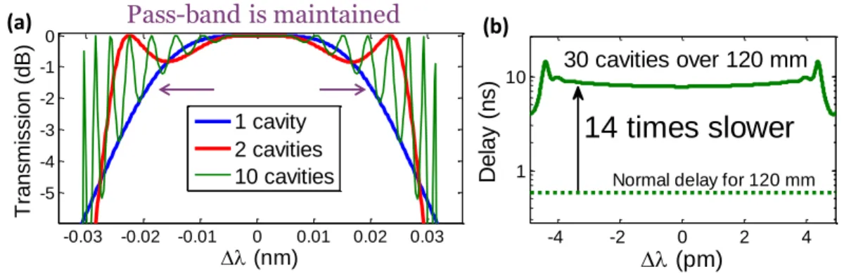
Δλ=2 nm. (c) CFBG superstructure which we have proposed and designed [90]. ... 30 Figure 2.13: Simulation and design of broad-band superimposed CFBG cavity arrays. (a) Transmission spectrum of 1 to 10 cavities to show how the pass-band is relatively maintained. (b) Delay with wavelength of a 30 superimposed CFBG cavity array. ... 31 Figure 2.14: Effect of phase noise on side-mode structure of a uniform FBG. This is a simulated example for a 100 mm long FBG with a 𝜅𝑎𝑐 of 50 m-1 and considering typical writing
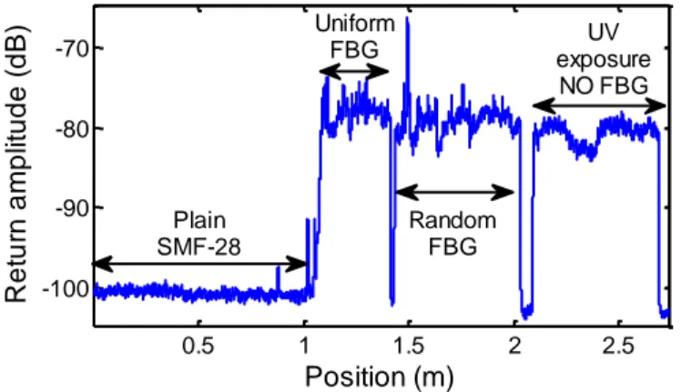
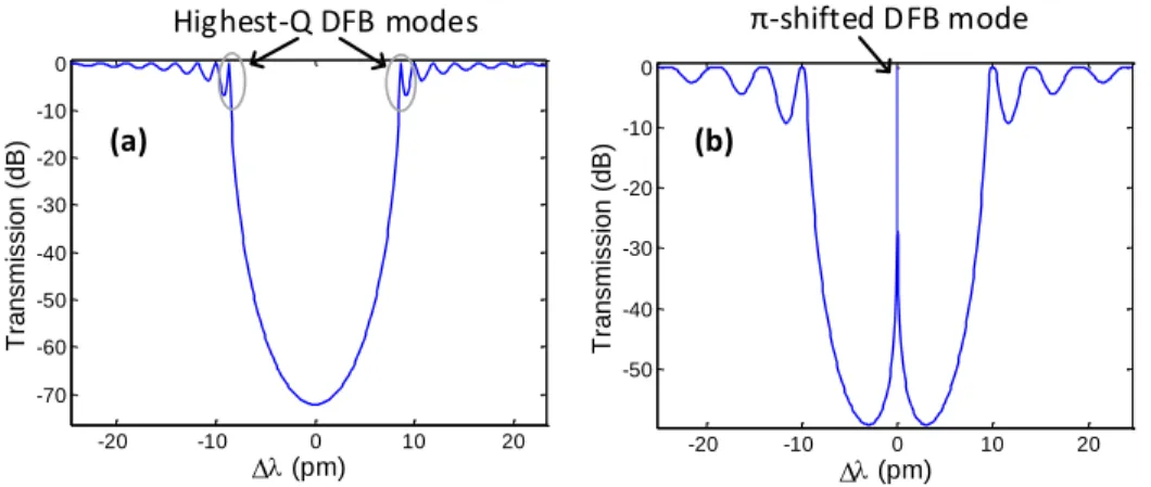
conditions. ... 32 Figure 2.15: Effect of UV exposure on back-scatter return signal from a OFDR measurement. .. 33 Figure 2.16: Calculated example of (a) a uniform FBG spectra and (b) a π-phase-shifted FBG. The FBG is 300 mm in length with a 𝜅𝑎𝑐 of 30 m-1. Central wavelength is 1550 nm. ... 34
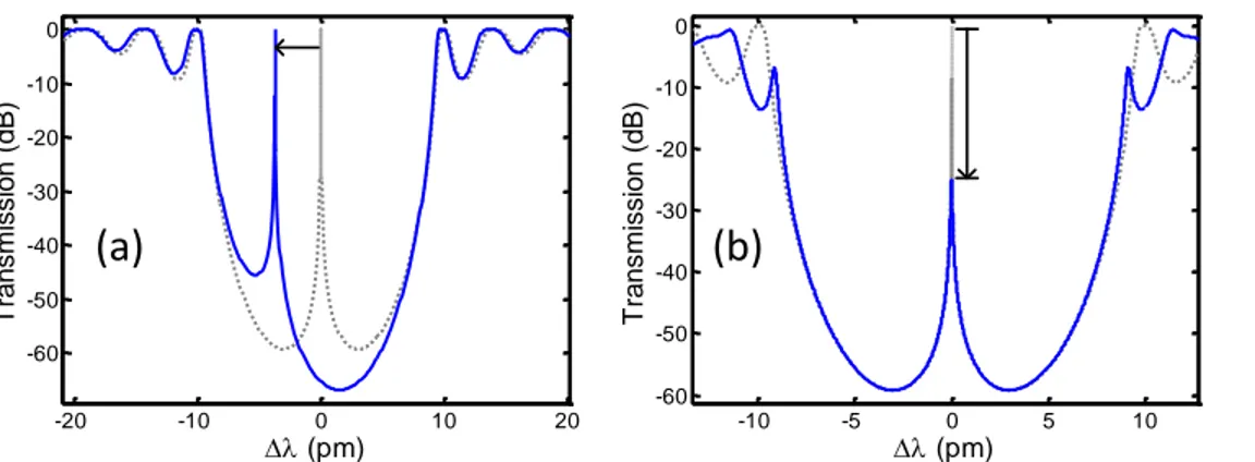
Figure 2.17: Calculated example of (a) a reduction in the phase-shift value (0.7 π , centered in FBG) and (b) a 20 % off-set from center of the π-phase-shift. Central wavelength is 1550 nm. The dotted gray line shows an ideal phase-shift. ... 35 Figure 2.18: Effect of increasing the phase-shift region, using an error function model. The dotted gray line shows an ideal phase-shift. (a) Calculated example showing a 2cm wide π-phase-shift. (b) Calculated example with a 9cm wide π-phase-π-phase-shift. (c) Calculated example of a 9cm wide phase-shift with an increased phase-shift value to re-center the DFB mode. ... 36 Figure 3.1: 3D design of the Fabulas station used for this thesis. ... 46 Figure 3.2: Schematic view of the Talbot interferometer used to write continuous FBGs. ... 47
Figure 3.3: Comparison of the modulator and piezo performance for a speed of 32 µm/s. The 2 lower graphs show the case of apodization. To maintain an acceptable quality in the saw-tooth wave, the piezo must be used below 20 Hz. ... 49 Figure 3.4: Optical circuit of the Luna OBR system. The top section represents the typical OFDR measurement interferometer, while the bottom section represents the patented Luna phase monitoring system to enable the use of low-coherence diode laser. ... 50 Figure 3.5: Measurement method ... 51 Figure 3.6: Experimental setup of the DFB laser test bench. ... 52 Figure 4.1: Experimental setup for: (a) FBG fabrication using Talbot interferometer and moving fiber, (b) SBS laser implementation with tuning pump and (c) linewidth characterization of pump and SBS emission. The beat note of linewidth characterization is measured with a fast photodiode and electrical spectrum analyser (ESA). ... 57 Figure 4.2 : Spectrum of 500 mm DFB FBG under test with 0.16-pm resolution. (a) DFB1 was fabricated to be the weak grating with a κac of 24 m-1, while (b) DFB2 is stronger with a κac of 45 m-1. The simulated transmission of the DFB mode with no gain is -26 dB and -63 dB for DFB 1 and 2, respectively (due to non-centered phase-shift). The Bragg wavelength of both FBGs is around 1549.5 nm. The resolution of simulated structure is 2 attometers. ... 59 Figure 4.3: SBS generated power as a function of pump detuning and power. The pump is detuned as shown in the upper inset (by approaching the DFB mode from shorter wavelengths). The SBS gain, moving with the pump, pushes the DFB mode (state 1, 2) until the maximum is reached (state 3). The mode then “recoils” back to its original position once the maximum gain is exceeded. To recover SBS, the pump must be detuned to a shorter wavelength (state 1) to re-initiate SBS generation. ... 60 Figure 4.4: SBS laser characterization. (a) Output power of DFB 1 and 2 with their respective efficiencies and threshold. (b) Linewidth of DFB 2, the most efficient and stable SBS DFB demonstrated here, measured from self-heterodyne technique at 100 MHz, with a decoherence delay time of 150 µs. The SBS emission is compared with the linewidth of the pump. Note that any jitter whiten this time will cause an increase of the linewidth. ... 62
Figure 4.5: Pump-Stokes beat frequency around 10.9 GHz observed directly at the output (SBS signal output) without the pump FBG filter. Measurement done with fast photodiode and ESA. ... 63 Figure 5.1: (a) Direct writing scheme using a Talbot interferometer for inscribing probe FBGs. (b) Position of fiber in respect with beam all along writing length for PM fibers. ... 67 Figure 5.2 : Reference characterization performed in SMF-28, which is expected to be the highest quality fiber available (most uniform neff(z)). (a) Refractive index characterization (around
neff = 1.4478), where the thin lines show 3 independent measurements and the thick line shows
the average of the 3. (b) Measured and simulated (dashed line) reflectivity spectrum of this 250 mm FBG shows little apparent chirp and near perfect structure. ... 69 Figure 5.3: Characterization of a small-core (4 µm MFD, 0.3 NA), PM fiber (PM1). (a) and (b) show two different fiber samples. Several independent tests are shown with their average. The exposure (therefore Δn) was varied in (a). The reflectivity spectrum of both samples is measured in (c) and (d) respectively and the spectra compared with a calculated spectrum using the measured refractive index variation in (a) and (b). ... 70 Figure 5.4: Characterization of a small-core, high NA fiber and non-PM fiber (SM2). (a) and (b) show two different fiber samples, (b) of long length. The thin lines are the 3 tests, while the tick like is the average of the 3. Note, the scale of Δneff in (b) is twice the scale of other figures.
... 71 Figure 5.5: Characterization of a 6µm mode field diameter PM fiber (PM2). (a) and (b) show two different fiber samples. 3 tests are shown with the average. The 3rd test in (b) was done by including ± 5 µm random displacement in the beam over ~5 cm range. ... 72 Figure 6.1: (a) Experimental setup for FBG writing. The system is a continuous direct writing scheme. The fiber moves at speed, v while the phase modulator moves the fringe pattern using a saw-tooth function with a frequency, f. (b) A commercial OFDR characterization system is used to find the frequency deviation along the fiber. ... 76 Figure 6.2 : Corrected 95 cm long uniform FBG fabricated in HNA1 fiber at 1555.3 nm. (a) Measured frequency deviation by OFDR from the average of the probe FBGs. (b) Comparison
of one of the un-corrected probe FBG spectra with the corrected required FBG, a zoom of which is reproduced (c), along with the theoretically designed spectra. ... 78 Figure 6.3: Corrected 95 cm long uniform FBG fabricated in PMHNA fiber at 1559.7 nm. (a) Measured frequency deviation by OFDR derived from the average of spectra of the 3 probe FBGs. (b) Comparison of one of the un-corrected probe FBG with the final corrected FBG which is reproduced and zoomed in (c) where it is compared with the theoretical spectra of a 95 cm long FBG. ... 79 Figure 6.4: Corrected DFB FBG of 30 cm fabricated in HNA2 fiber at 1578.1 nm. (a) Measured frequency deviation with OBR from 3 probe FBG average. (b) Comparison of one of the un-corrected probe FBGs (in reflection) with the final un-corrected DFB (in transmission). A simulated DFB with its final κac strength was calculated with the frequency deviation in (a) to show what the DFB would have looked like in transmission if not corrected. The final corrected DFB is reproduced in (c) where it is compared with a theoretically perfect DFB. 80 Figure 7.1: Schematic of a PS-DFB-FBG including the system variables. ... 86 Figure 7.2: Power distributions along the PS-DFB-FBG for comparison of field calculation using two methods: iterative approximated field fit (IAFF) used in this paper as a fast method, and a differential equation solution based on shooting and Runge-Kutta (S & RK) algorithm as a standard method. The simulated grating is 300 mm long, with a 𝜅𝑎𝑐 of 40 m-1, a loss of 0.03
dB/m and a π-phase-shift at 126 mm (-24 mm off-center). The pump power is 3W. ... 87 Figure 7.3: Justification for the choice of PS-DFB-FBG length and strength. (a) The threshold power is shown versus FBG length for a constant 𝜅𝑎𝑐𝐿 = 12. (b) A limitation from non-linearity is shown as the strength of FBG is increased for a constant pump power (8.8 W): the DFB mode displacement (𝛿𝑓𝐷𝐹𝐵) is tuned towards the outside of the stop-band bandwidth (Δ𝑓𝐷𝐹𝐵). All FBGs simulated here have a π-phase-shift at -5% of the length away from the center. The FBGs in (b) are 200 mm long. ... 88 Figure 7.4: The effect of non-linearity on the DFB mode. The DFB mode is detuned (red-shifted) toward the edge of the stop band as power inside the FBG is increased. Case of (a) a π-PS FBG and (b) a 0.75π-PS FBG. The lasing lines are represented by high gain lines (gain as seen by the input seed). The arrows with + and – signs on top show a red- and blue-shift of the lines
with increase and decrease of power, respectively. FBGs are 300 mm long with a centered phase shift. 𝜅𝑎𝑐 is 40 m-1 and the loss is 0.03 dB/m. ... 89
Figure 7.5: Effect of phase-shift value. (a) The activation threshold (when increasing the pump from 0 W initially), shut-down threshold (when decreasing the pump after achieving lasing state) and slope efficiency are shown with varying phase-shift values (b) An example of activation/shut-down hysteresis is shown with a phase shift of 0.6π. FBGs are 300 mm long with a phase shift at -8% from center. 𝜅𝑎𝑐 is 40 m-1 and the loss is 0.03 dB/m. ... 90 Figure 7.6: Optimization of phase shift (a) values and (b) positions at different pump levels. The optimization in (a) considers activation threshold. FBGs are 300 mm long. Phase shift is at -8% from center and 𝜅𝑎𝑐 is 40 m-1 in (a). The loss is 0.03 dB/m. ... 91 Figure 7.7 : (a) Schematic of the fabrication system using a Talbot interferometer and moving fiber, (b) PS-DFB-FBG laser implementation with a 1480 nm pump. The FBG is placed on a cooled-down metal groove immersed in glycerin. ... 92 Figure 7.8: Output power characterization of a 250 mm long π-PS fabricated FBG considering different bases for thermal management. Base 1 is a thick metal cooled plate (at 10°C) in which the fiber is placed in a 1 mm wide grove covered in glycerin. Base 2 is a thin metal plate in which the fiber is placed bare on the surface (no grove or glycerin). Base 3 is a thin plastic base in which the fiber is also placed bare on the surface. (b) Simulation of efficiency versus effective non-linearity ratio due to thermal gradient from non-uniform field for 300 mm, π-PS at -8% from center and 40 m-1 FBGs. ... 93 Figure 7.9: A 0.7π phase-shifted FBG on base 1 where the output power shows hysteresis of activation/shutdown. This 250 mm long FBG has its phase shift placed at -20 mm from center with a 𝜅𝑎𝑐 of ~ 70 m-1. ... 94 Figure 7.10: Comparison of measurement and simulation results for series of fabricated FBGs using a large 𝛾𝑒𝑓𝑓 (=35𝛾). (a) Pump power threshold and (b) slope efficiency of output power with phase-shift position. The theoretical results are fitted to the experimental data using a loss of 0.1 dB/m and a coupling constant of 70 m-1. All FBGs are 250 mm, the current length limit of our temperature controlled base. ... 95 Figure 8.1: Bandwidth (between first zeros) of a uniform FBG along with length ... 98
Figure 8.2: Example of the 3 main defects in FBGs: (a) phase shifts (0.6 and -2 rad at 2 locations in a 300 mm FBG), (b) slow wavelength variation (10 pm quadratic chirp on a 300 mm FBG) and (c) high frequency random phase noise (0.3 rad amplitude, 100 µm spatial variation, on a 10 mm cosine squared apodized FBG. ... 99 Figure 8.3: Fully apodized FBG spectra (cosine square, 7 mm) for a piezo written and a modulator written FBG. ... 101 Figure 8.4: Position error noise, hence phase error noise, measured by the stage. The measured data was spatially averaged over the illumination spot size of 120 µm... 104 Figure 8.5: Comparison of the proposed equation (8.11) with simulation for no-loss DFB FBGs with a π, centered phase-shift. ... 108 Figure 8.6: Calculated maximum slope efficiency for various centered phase-shifted FBG designs (variation of the inscribed phase-shift value), with thermal non-linearity included. An optimal phase shift (π, for lowest threshold) is dynamically applied through (ex: heating) to “start” the lasing only, then removed to calculate the “maximum slope efficiency”. ... 112 Figure 8.7: Operation results from 300 mm long phase-shifted DFB Raman fiber lasers. (a) Laser operating at 1120 nm (1064 nm pump) and (b) another design operating at 1178 nm (1120 nm pump) ... 113 Figure 8.8: Generation of SBS outside of the DFB FBG stop-band during Raman emission. .... 114
LIST ACRONYMS AND ABBREVIATIONS
CFBG Chirped fiber Bragg grating DFB Distributed feedback
EO Electro-optic
EOM Electro-optic modulator ESA Electrical spectrum analyser FBG Fiber Bragg grating
FFT Fast Fourier transform FSR Free spectral range FUT Fiber under test MFD Mode field diameter NA Numerical aperture
NL Non-linear
OBR Optical back-reflectometer OCT Optical coherence tomography
OFDR Optical frequency domain reflectometry OSA Optical spectrum analyser
PS Phase shifted
RE Rare earth
RI Refractive index RIU Refractive index units RK4 Runge-Kutta, 4th order
SBS Stimulated Brillouin scattering SRS Stimulated Brillouin scattering
LIST OF APPENDIX
CHAPTER 1
INTRODUCTION
Optical fibers play an important role in our society: from the backbone of our telecommunication network to advanced laser sources and sensing applications. One type of device has accompanied researchers and engineers since 1978, a decade after the beginning of the grand adventure of optical fiber: fiber Bragg gratings (FBGs). These devices are an inscribed periodic change in the effective refractive index inside a waveguide, which acts as a wavelength selective reflective filter. Although such filters had been predicted in the mid 70ies [1], it remained a difficult device to fabricate. This
issue was resolved purely by accident, as many discoveries are, at the Canadian Communication Research center in 1978 by Hill, Fujii, Johnson and Kawasaki [2]. When injecting light from an argon ion laser into a germanium-doped-core silica fiber, Hill et al. noticed a reflection which grew over time. They then discovered that this reflection was permanent: a narrow-band filter had been successfully imprinted on the fiber. This was caused by a 4% back-reflection between the fiber output-ends, which generated a standing wave and slowly wrote a grating inside the core. When the Ar-ion laser mirror facing the fiber was removed, the authors realised that the laser kept oscillating, thanks to the reflection from the newly formed FBG, as shown in Figure 1.1. Photosensitivity in optical fiber was therefore discovered and the first FBG was thus demonstrated.
Figure 1.1: Hill et al.’s experiment discovering photosensitivity and how to make FBGs using an Ar-ion laser. A Fresnel reflection caused a standing wave in a Ge-doped silica fiber, which in
turn wrote a permanent grating in the fiber through photosensitivity.
Unfortunately, this method of writing a grating is restricted to the photosensitive wavelength region, and with periods that cannot be altered to arbitrary wavelengths. Since then, writing techniques and more complex and optimized designs of FBGs have appeared. Present day FBGs are written using holographic techniques [3], a more convenient way which allows writing at
Ar-Ion gaz-cell
High R mirror
Brewster window Injection
objective Ge core doped silica fiber
St anding wave 4% Fresnel reflection Laser emission
virtually any wavelengths. FBGs have become a crucial part of the telecommunication infrastructure for implementing narrow-band selective filters to select and separate channels [4]. Complex designs were also proposed to select multiple channels at once [5, 6]. FBGs have also had an important role in solving a major long-distance communication issue: dispersion of light in optical fibers. By chirping the FBG (CFBGs), i.e. linearly changing the resonance wavelength along the position, such filters could be used as dispersion compensators [6-8]. Being small and customizable devices, they have been used ever since the beginning of the telecoms explosion. Today, thanks to phase encoding, electronic [9] or digital [10] post-processing techniques are used for dispersion compensation, which does not require any physical device and has reduced the need for CFBGs.
FBGs have been also used as laser cavity reflectors and later, as distributed feedback (DFB) lasers, a type of laser where the feedback happens all along the FBG, i.e. in which a mode oscillates inside the grating. The very first proposed application of FBG by Hill et al. was as a reflector for their argon-ion laser [2]. Since FBGs offer tunable reflectivity and wavelength, and thanks to their narrow band, they can be used to select a specific lasing wavelength in a broad-band gain medium. FBG based DFB lasers have also shown exceptional performance as a single-frequency laser source, as will be described in section 2.3 of the next chapter.
Since their invention, FBG fabrication techniques and applications have increased in number immensely. Indeed, FGB applications can be found in almost all fields where optical fiber is used: telecommunications, sensing, laser sources, biomedical and quantum optics and more. Many of these areas were addressed during the course of my PhD, as my work focused on developing new fiber tools based on FBGs which can be applied, and have been applied, to the above applications. Several new ideas and complex designs of FBGs have been proposed and investigated throughout my years of research, but here we focus on the main contributions, the subject of this thesis: the fabrication of perfect ultra-long FBGs.
“Ultra-long” is of course a relative term but is typically defined as being >20 cm long. This is compared to the current typical gratings length (<10 cm) which are limited by the length of the phase-masks used to write them. The characteristics of such long-length gratings have been known and pursued for a long time, but the technology and known techniques at the time could not produce such gratings. My predecessors at Polytechnique had solved some of the problems, such as
high-speed writing, perfect apodization, high tunability on written wavelength and phase and reduced phase noise from vibrations [11, 12] by implementing a novel system which will be presented in the next chapter. However, by attempting various complex devices on specialty fibers, new problems specific to ultra-long FBG fabrication were revealed. This has led to the development of new fabrication techniques and new devices, which will be described in this thesis.
Ironically, the best writing technique which yields the highest quality FBGs (no chirp nor phase noise or defect) remains the very first technique developed by Hill et al., since the grating is written by a perfect standing wave. As mentioned before, such a technique is unfortunately not suitable for all operating wavelengths and generally limited to the UV. All writing techniques have tried to reproduce such high quality FBGs, which could never be completely achieved. When going into ultra-long FBGs, such difficulties only tend to increase. The goal of this thesis is therefore to return to the top-quality FBGs produced by Hill et al., while applying it to fully tunable, ultra-long FBGs. Such an accomplishment could, as we have already started to demonstrate, lead to new types of devices in non-linear optics.
1.1 The Motivation and problem
A type of FBG structure which will be studied in this thesis, and which gains much from ultra-long length is a phase-shifted DFB grating. As stated earlier, a DFB mode resonates throughout the FBG length. Uniform FBGs have intrinsic DFB modes, which appear spectrally on either side of the stop-band (central resonance band) and come from a Fabry-Perot-like oscillation from the abrupt ends of the FBG. A DFB mode can be created inside the stop-band, which would offer a much higher confinement and therefore quality-factor. To do so, the phase of the FBG must be shifted by a half-period of the grating (π-shift, also considered as quarter-wavelength). More details on phase-shifted DFB structures will be given in the next chapter.
Ultra-long FBGs have the advantage of enhancing grating characteristics, especially in terms of frequency bandwidth and in the case of DFB modes, their linewidth. For a constant strength (constant transmission, losses), a FBG will see its bandwidth reduced inversely with its length. The same goes for the linewidth of DFB resonance modes of a phase-shifted FBG. This brings a highly reduced linewidth of laser emission from such structures. It can also be pointed out that ultra-long FBGs will have a reduced requirement on the coupling constant (refractive index change) with
increasing length for a constant overall reflectivity, as this strength is the product of coupling constant, 𝜅𝑎𝑐, and length, L (called 𝜅𝑎𝑐𝐿). However, one must remain cautious when pointing out this advantage: short FBGs may have a higher requirement on coupling constant, therefore on laser writing exposure, but the UV exposed-length is also shorter, therefore total fabrication time can be equivalent to an ultra-long FBG with weak UV exposure. Therefore, it is better to compare FBGs at constant strength. Nevertheless, the lower requirement on refractive index change for ultra-long FBGs allows the use of a wider range of writing techniques and fibers.
These advantages offer new possibilities for applications: ultra-narrow filters, long photon lifetime cavities, high-internal optical fields for non-linear processes, low thresholds for lasers, narrow linewidth lasers etc. For instance, these properties can allow optically pumped stimulated Raman scattering (SRS) narrow linewidth fiber lasers to be fabricated, which can be implemented at any wavelength, since Raman gain is not specific to a spectral band, contrary to rare-earth dopants. Such lasers could be useful in many applications, one of which is the laser guide-star [13] which requires a narrow-line (high coherence) laser to lock on the 589 nm sodium line. However, there is little choice for amplification at this wavelength. On the other hand, the second harmonic of a SRS DFB fiber laser at 1178 nm could accomplish that task easily, while offering fine tunability. This is just one of the many potential applications for such a technology.
Despite these advantages, the ultra-long FBGs is not available in the market: only specialised labs, including ours, can fabricate such gratings. Even then, the specifications are difficult to achieve. The reason for this is that fabrication of ultra-long gratings is very difficult: a continuous writing system with top-of-the-line air-bearing stages are required. The best system was developed in our lab before my PhD: a modulator-based interferometer for high-speed, with zero vibration and perfect apodization [12]. Despite this, several problems remained unsolved, as were progressively discovered at the beginning of this PhD:
• Phase shift was not reproducible and difficult to control on the modulator system. This was found to be because of lack of feedback on the phase applied by the modulator.
• Difficult writing conditions due to environment change (noise, reproducibility issues, etc.) • FBG are not reproducible in specialised fibers (in most fibers except standard SMF-28).
These issues were therefore quite limiting for studying specialised structures and had to be solved to properly attack the initial goal set at the beginning of my PhD: to design and optimize special structures for non-linear optical applications, such as stimulated Brillouin and Raman scattering laser based on DFB phase-shifted FBGs. Designing new structures also requires good modeling and simulation. Models already existed for such lasers, however the proposed simulation methods were so time consuming, that very little study was possible with varying parameters. Also, except for a few demonstrations, which did not fit the prevailing models, there were no experimental studies on an extended set of FBGs due to severe limitations in their reproducibility. Due to these obstacles, the objectives of my PhD had to be redefined as will be described in the next sub-section.
1.2 Objectives
Considering the problems described above, we can state four objectives for the PhD described below.
1. Understanding the limitations of ultra-long FBG writing:
The first objective of this Thesis is to understand the problems that limits the fabrication of perfect gratings. Understanding the limitations is useful not only for improving fiber fabrication technique, but also to understand what structures (phase, amplitude) can be inscribed in which fibers.
2. Develop fabrication technique for perfect and reproducible Ultra-long FBG
The goal of this objective is to reach the perfect gratings, as demonstrated by Hill et al. in 1978, while maintaining complete tunability on the wavelength and flexibility on the structure (phase, amplitude) to inscribe.
3. Develop a DFB model and simulation scheme for understanding and optimizing Raman DFB lasers
Understanding the physics of a device is crucial before any design can take place. This objective is to develop a proper model representing what is observed experimentally, simulate the effect of all potential parameters on performance to understand device operation and develop an optimization method.
4. Design, optimize and demonstrate high performance Raman and Brillouin gain DFB lasers
This objective is the experimental realisation of optimized and high-performance Raman and Brillouin gain DFB lasers. To do so, experimental FBGs must be tested with varying parameters and compared with the model. High performance (low threshold, high efficiency) is aimed or at least a better understanding on the requirements for optimal future performance.
1.3 Organisation of thesis
As a start for the thesis, a detailed literature review will be made on various subjects covered in the thesis or during my PhD. First, a review of FBG theory and simulation methods. Second, a review of FBG writing techniques, including, of course, a state-of-the-art on ultra-long writing. Third, various applications related to work done during my PhD will be reviewed. Those are not directly linked to the subject presented in the articles of this thesis, but they were instrumental in achieving the first objective by identifying problems of the writing technique. Finally, theory and state-of-the-art will be presented concerning DFB Raman and Brillouin fiber laser, the subject of the 1st and 4th article and of the two last objectives.
After this literature review, an introduction chapter to the presented article will be made. This chapter will describe the methodology and link between each article. Following this, 4 articles are presented:
• The first article will present my initial work on ultra-long DFB lasers, where issues of phase-shift and writing stability were resolved. A Brillouin gain DFB fiber laser in SMF-28 is also presented and brings some insights on Raman and Brillouin DFB fiber laser which has been useful for the study of Raman gain DFB fiber laser.
• The second article is directly related to the first objective and describe the cause of why ultra-long FBGs in specialised fibers are not reproducible and often suffer from bad quality. This cause is fiber non-uniformity. A measurement method for the fiber’s effective refractive index is presented in the paper.
• The third article describes the solution to the problem explained in the second article. This is directly related to the second objective. A new ultra-long FBG fabrication technique is presented which can adapt to any fiber non-uniformity.
• The fourth and last article is on a vast study, both theoretically and experimentally, on Raman gain DFB fiber lasers. The FBGs in this article are inscribed using the technique described in the 3rd article. This paper answers the two last objectives.
Following these 4 papers, a general discussion will be made concerning the overall work presented in this thesis. This discussion will be followed by a concluding chapter.
CHAPTER 2
LITERATURE REVIEW
In this chapter, a detailed literature review is presented on fiber Bragg gratings (FBGs). First, a description of FBG theory and how they are fabricated will be shown. Then, some specialised application which were studied during my PhD will be described and reviewed. As the main subject of this thesis is ultra-long phase-shifted DFB FBGs for laser applications, the literature review focuses on this subject in the last section.
2.1 Modeling of fiber Bragg gratings
2.1.1 Theory of fiber Bragg gratings
This section will describe the theory of FBGs. For clarity purpose, this description will be simplified to the relevant expressions. For a more detailed demonstrations of those expressions, various work can be explored more thoroughly such as Gloge’s [14] for weakly guided mode theory and Kashyap’s [15] for grating coupling mode theory.
A fiber Bragg grating is a periodic variation of the refractive index (RI) in a guided medium, usually an optical fiber, as shown in Figure 2.1. There are several techniques that can be used to inscribe this structure, as will be discussed in the next section, which usually require interferometric methods as the period of the RI variation is sub-micron. The general mathematical description of a Bragg grating in terms of RI variation is as follows [15]:
𝑛(𝑧) = 𝑛0+ 𝛥𝑛̅̅̅̅(𝑧) + ∑ 𝛥𝑛𝑁(𝑧) cos (2𝜋𝑁𝑧
Λ + 𝜙𝑁(𝑧))
∞
𝑁=−∞
(2.1) Where 𝑛0 is the effective RI of the guided mode before an FBG is inscribed, Δ𝑛̅̅̅̅(𝑧) is the average RI increase after the FBG is inscribed, N is an integer order of the decomposed Fourier harmonic component of the RI modulation, 𝛥𝑛𝑁(𝑧) the modulation amplitude for Nth harmonic, 𝛬 is the
grating period and 𝜙𝑁(𝑧) is any other phase variation along the grating of the Nth harmonic. During
fabrication, the average index rises, and the modulation RI and phase are parameters which can be engineered along the propagation axis of the fiber. Note that some fabrication techniques generate higher-order FBGs, which have several resonances at higher harmonic frequencies (shorter wavelengths). For example, a 2nd -order FBG with a first order resonance wavelength at 3 µm, will
also have a resonance at ~1550 nm and for the third order, possibly at ~775 nm (𝛥𝑛𝑁=3). Using most fabrication techniques, FBGs can usually be approximated, with good reliability, by a perfect 1st order sinusoidal modulation, therefore simplifying Eq. (2.1) by neglecting other harmonics as:
𝑛(𝑧) = 𝑛0+ 𝛥𝑛̅̅̅̅(𝑧) (1 + 𝑣(𝑧) cos (
2𝜋𝑧
𝛬 + 𝜙(𝑧))) (2.2)
Where 𝑣(𝑧) represents the visibility of the modulation (0 ≤ 𝑣 ≤ 1), which can be controlled by a process called apodization. The inscribed modulation 𝛥𝑛̅̅̅̅ is generally small and can be considered as a perturbation of the RI.
Figure 2.1: Schematic representation of a uniform FBG for (a) perfect visibility (v = 1) and (b) reduced visibility (v ~ 0.5)
To consider the effect of such a periodic RI change on a propagating light wave, we must first consider the constitutive equation of polarisation:
𝑃 = 𝜀0(𝜀𝑟− 1 + Δ𝜀(𝑧))𝐸 (2.3)
Where 𝜀𝑟 is the relative permittivity and the term in parenthesis the first order susceptibility 𝜒(1) perturbed by the periodic modulation in the permittivity, Δ𝜀(𝑧). Using the relationship
between RI and permittivity (𝑛2 = 𝜀
𝑟), we have:
(𝑛0+ 𝛿𝑛(𝑧))2 = 𝜀𝑟+ 𝛥𝜀(𝑧) (2.4)
Where 𝛿𝑛(𝑧) is the RI perturbation term in Eq. (2.2). considering this perturbation to be very small, the effect on the permittivity can be simplified as:
𝛥𝜀(𝑧) ≈ 2𝑛𝛿𝑛(𝑧) = 2𝑛𝛥𝑛̅̅̅̅(𝑧) (1 + 𝑣(𝑧) cos (2𝜋𝑧 𝛬 + 𝜙(𝑧))) (2.5) x n Δn Δn Λ n0 x n Δn Δn Λ n0 (a) (b)
By placing equation (2.5) inside the constitutive relation, equation (2.3), the effect of the grating inscription on the induced polarisation is:
𝑃 = 𝜀0(𝜀𝑟− 1 + 2𝑛𝛥𝑛̅̅̅̅(𝑧) (1 + 𝑣(𝑧) cos (
2𝜋𝑧
𝛬 + 𝜙(𝑧)))) 𝐸 (2.6)
Let us now define the total transverse field in the fiber as:
Where 𝜉𝜈𝑡 and 𝜉𝑢𝑡 are the normalised transverse electrical fields distribution of the 𝜇th and 𝜈th
guided coupled-modes orders, 𝐴𝜈 and 𝐵𝜇 the forward and backward fields, respectively, along the
propagation axis and 𝛽𝜈 and 𝛽𝜇 the propagating constants of the two guided modes. From the field definition of equation (2.7), we can define the forward reference field (R) and the coupled backward signal field (S) as:
𝑅 = 𝐴𝜈𝑒− 𝑖 2(𝛥𝛽𝑧−𝜙(𝑧)) 𝑆 = 𝐵𝜇𝑒− 𝑖 2(𝛥𝛽𝑧−𝜙(𝑧)) (2.8)
In which Δ𝛽 represents the phase mismatch: 𝛥𝛽 = 𝛽𝜈+ 𝛽𝜇−
2𝜋
Λ (2.9)
Coupling will therefore occur when this 𝛥𝛽 tends to zero. For a FBG in a single mode fibre, the coupled waves are counter-propagating and are of the same order (ν = μ), therefore the resonance wavelength, i.e. the Bragg wavelength, can be defined as:
𝜆𝐵= 2𝑛𝑒𝑓𝑓Λ (2.10)
Where 𝑛𝑒𝑓𝑓 is the effective RI of the guided mode.
Considering weakly guided mode theory as developed by Gloge [14] and well described in many subsequent works [15, 16], the RI perturbation of equation (2.6), and differentiating the defined fields of equation (2.8), the coupled-mode equations can be expressed as:
𝐸𝑡 =1
𝑑𝑅 𝑑𝑧 = −𝑖 [𝜅𝑑𝑐+ Δ𝛽 2 − 1 2 𝑑𝜙(𝑧) 𝑑𝑧 ] 𝑅 − 𝑖𝜅𝑎𝑐∗ 𝑆 𝑑𝑆 𝑑𝑧 = 𝑖 [𝜅𝑑𝑐+ 𝛥𝛽 2 − 1 2 𝑑𝜙(𝑧) 𝑑𝑧 ] 𝑅 + 𝑖𝜅𝑎𝑐𝑆 (2.11)
Where 𝜅𝑎𝑐 and 𝜅𝑑𝑐 are the modulation and dc coupling constants, respectively. 𝜅𝑎𝑐 is linked to the RI modulation depth, Δ𝑛 and influences the strength of the coupling. 𝜅𝑑𝑐 is linked to the average
RI variation 𝛥𝑛̅̅̅̅. Its effect is adding a local phase, thus altering the phase matching condition. If 𝜅𝑑𝑐 increases, it will simply move the resonance wavelength and is therefore the reason why strong
FBGs tend to be red-shifted in wavelength for the same period Λ. If 𝜅𝑑𝑐 is varied spatially, it will induce a chirp, having the same effect as a non-linear phase variation 𝜙(𝑧). Based on equations (2.1) and (2.2), the coupling constants are defined by:
𝜅𝑎𝑐 = 𝛽𝑐𝜀0 ∬ Δ𝑛 2 𝜉𝜈𝑡𝜉𝑢𝑡𝑑𝑥𝑑𝑦 +∞ −∞ = 2𝜋𝑛𝑒𝑓𝑓Δ𝑛 𝜆 𝜂 𝜅𝑑𝑐 =4𝜋𝑛𝑒𝑓𝑓Δ𝑛̅̅̅̅ 𝜆 𝜂 = 2𝜅𝑎𝑐 𝑣 (2.12)
Where 𝜂 (dimensionless) represent the overlap integral of fields with index modulation Δ𝑛 in the core cross-section. The coupled-mode equations (2.11) can be solved by using standard eigenvalue techniques [17] for a uniform FBG (constant 𝜅𝑎𝑐, 𝜅𝑎𝑐 and 𝜙) of length L. The ratio between the
reflected field S(0) and the reference input field R(0) can be expressed analytically by [15]: ρ = 𝑆(0)
𝑅(0)= −
𝜅𝑎𝑐sinh(𝛼𝐿)
𝛿 sinh(𝛼𝐿) − 𝑖𝛼 cosh(𝛼𝐿) (2.13)
Where 𝛿 represents the resonance mismatch: 𝛿 = 𝜅𝑑𝑐+ Δ𝛽 2 − 1 2 𝑑𝜙(𝑧) 𝑑𝑧 (2.14)
And 𝛼, the coupling term:
Equation (2.13) represents the entire spectral characteristics of a uniform FBG, as can be seen in Figure 2.2. The peak reflectivity of the FBG (where Δ𝛽 = 0) depends only on the modulation depth and on the length and is simply:
|𝜌𝛿=0|2 = tanh2(𝜅𝑎𝑐𝐿) (2.16)
Where the product 𝜅𝑎𝑐𝐿 is often considered as the strength of the FBG. The reflection spectra between the first zeros around the central resonance is considered as the stop-band (in reference to a band-gap of a periodic structure, as a FBG is effectively a weak 1D photonic crystal). The width of this stop-band can be calculated as:
Δ𝜆 = 𝜆𝐵
2
2𝜋𝑛𝑒𝑓𝑓𝐿√(𝜅𝑎𝑐𝐿)2+ 𝜋2 (2.17)
Examples of reflection, transmission and group-delay spectra are shown in Figure 2.2. As can be seen, uniform FBGs have important side-structure outside of the stop-band. This side-structure comes from high frequency variations, such as the abrupt square shape of the uniform FBG, but can also appear due to noise along the FBG as will be discussed in Section 2.2. The side-lobes are normally minimised through apodization: a process by which the 𝜅𝑎𝑐 (more specifically, the visibility of fringes) is slowly varied along the grating. As this thesis focuses on ultra-long FBGs, a comparison is given in Figure 2.2 between a typical 5 cm length grating and a 30 cm ultra-long version, for a similar 𝜅𝑎𝑐𝐿 strength. As can be seen, the main interest of the ultra-long version is a
narrowing in the spectral characteristics of the FBG, such as it’s band-width, and an increase in the photon trap-time within the structure, strongly influencing group delay.
Figure 2.2: Example of FBG (a) reflection, (b) transmission and (c) group delay of reflection spectra as calculated by the transfer-matrix method (section 2.1.2). A typical 5-cm short FBG is
compared with an ultra-long 30-cm FBG for the same strength (κacL = 4).
1549.96 1550 1550.04 0 500 1000 1500 2000 2500 (nm) D e la y (p s) L=5 cm L=30 cm 1549.96 1550 1550.04 -25 -20 -15 -10 -5 0 (nm) R e fl e ct io n (d B) L=5 cm L=30 cm (a) (c) 1549.96 1550 1550.04 -30 -25 -20 -15 -10 -5 0 (nm) T ra n smi ssi o n (d B) L=5 cm L=30 cm (b)
Long-period gratings (LPGs), on the other hand, scatter the guided light in the forward direction. As their name suggests, these structures have much longer periods (tens of µm to mm) instead of the sub-µm periods of FBGs. These structures can couple different propagation modes in a wave-guide in the same direction, such as a core-mode with cladding modes in an optical fiber. The model is similar to FBGs, except that equation (2.7) must now describe modes in the same direction with different 𝑛𝑒𝑓𝑓, therefore different propagation constants 𝛽. The resonance condition (2.9) remains the same, but depends on a difference of effective refractive index (𝑛𝑒𝑓𝑓𝜇− 𝑛𝑒𝑓𝑓𝜈). Since LPGs were not studied during my PhD they have not been considered in depth in this thesis. The above gives a general idea of the behavior of a uniform FBG. However, in this thesis, complex structures of FBGs are studied. To understand these structures, simulating their behavior is a crucial step in their design. Simulation techniques will therefore be reviewed in the next section.
2.1.2 Simulation techniques for non-uniform FBG
The most common and flexible technique used to simulate a non-uniform FBG structure is called the Transfer-Matrix Method (TMM) [15]. This method consists in separating the FBG into M uniform sections for which the exact analytical solution is known (equation (2.13)). Each section can be represented in the form of a matrix, as shown schematically in Figure 2.3 and represented by: [𝑅(0) 𝑆(0)] = 𝑇 [ 𝑅(Δ𝑧) 𝑆(Δ𝑧)] = [ 𝑇11 𝑇12 𝑇21 𝑇22] [𝑅(Δ𝑧)𝑆(Δ𝑧)] (2.18) With the matrix elements:
𝑇11= cos(𝛼Δ𝑧) + 𝑖𝛿 sin(𝛼Δ𝑧) 𝛼 (2.19) 𝑇22= cos(𝛼Δ𝑧) −𝑖𝛿 sin(𝛼Δ𝑧) 𝛼 (2.20) 𝑇12 = 𝑖𝜅𝑎𝑐sin(𝛼Δ𝑧) 𝛼 (2.21) 𝑇21 =𝑖𝜅𝑎𝑐sin(𝛼Δ𝑧) 𝛼 (2.22)
Figure 2.3: Schematic representation of a uniform FBG Δz section represented by a single matrix, with an integer number of periods.
Any phase variation in the grating between two sections can be calculated by adding a phase matrix between the twin section matrix, as shown below in equation (2.23) below. This is extremely useful to model phase-shifted distributed feedback structure, the main subject of this thesis, as discussed by Haus and Lai [18].
𝑇𝜙= [𝑒−𝑖Δ𝜙 2⁄ 0
0 𝑒𝑖Δ𝜙 2⁄ ] (2.23)
As light propagates from one section to another, which need not be identical (different 𝜅𝑑𝑐, 𝜅𝑎𝑐 and 𝜙), a transfer matrix can be calculated which represents the FBG as a whole:
[𝑅(0)𝑆(0)] = 𝑇1𝑇2… 𝑇𝑁[𝑅(𝐿)
𝑆(𝐿)] = 𝑇 [ 𝑅(𝐿)
𝑆(𝐿)] (2.24)
With this transfer matrix, the input (z = 0) and output fields (z = L), R and S may be calculated. By assuming a normalised input reference (R(0) = 1) and zero signal back-propagating input from the other end (S(L) = 0), the reflected and transmitted field solutions are found as:
𝑅(𝐿) = 1
𝑇11 (2.25)
𝑆(0) =𝑇21
𝑇11 (2.26)
Each transfer matrix is considered for one particular wavelength. Therefore, to calculate a reflection and/or transmission spectrum, a transfer matrix must be calculated for each wavelength. From these values, both the amplitude and phase of the reflected/transmitted signals can be calculated, thus characterising the behavior of a complex FBG. Knowing the phase, the group velocity can be calculated as its derivative, as shown in Figure 2.2(c). Once the solution at position
x
nR
S
R
S
x=0
x=Δz
L is found, the FBG's internal field can also be determined by applying successively the matrix
multiplication in equation (2.18) from 𝑧 = 𝐿 to 𝑧 = 0 from the definition of R and S as shown in equation (2.8). Gain and loss can be added either in the phase matrix of equation (2.23) as a real exponent, or directly in the coupled-mode equations (2.11) as an imaginary 𝜅𝑑𝑐 (this was used in the simulation of article 4).
This TMM is extremely powerful and has been used for all simulations shown in this thesis. However, there are limitations, as discussed by Yamada et al.[19]. Indeed, the transfer-matrix supposes each section is an analytical solution to an integer number of grating period uniform FBG. The phase error can become important (will mostly affect the side-lobes) for short sections in which this condition is not respected. However, by maintaining the sections long (𝑑𝑧 ≫ Λ), this phase error becomes negligible. The transfer-matrix method is shown schematically Figure 2.4(a) and compared with other methods described below.
Figure 2.4: Schematic representation of the 3 simulation techniques for simulating a FBG: (a) transfer matrix method (TMM), (b) thin-film method and (c) Rouard’s method.
When dealing with small structures, another technique can be used: the thin-film method [15], as shown schematically in Figure 2.4(b). In this method, the FBG is approximated as a stack of thin
x
nT
1T
2T
3T
Δz1T
Δn1T
Δn2T
Δz1T
Δz2T
Δz2T
Δn1n
1n
2Λ
Δz
Δn
R
S
R
S
(a)
(b)
(c)
films, therefore considering a square-shaped periodic structure for the RI instead of a sinusoidal structure proposed in equation (2.2). In such a case, each step is considered as a simple Fresnel reflection followed by a propagation matrix. A grating half-period is therefore represented by:
[𝑅(0)𝑆(0)] = 𝑇Δ𝑛𝑇Δ𝑧[𝑅(Δ𝑧)𝑆(Δ𝑧)] (2.27) 𝑇Δ𝑛 = 1 𝑡1[ 𝑟1 1 1 𝑟1] , 𝑇Δ𝑧 = [𝑒 −𝑖2𝜋𝑛2Δ𝑧 𝜆⁄ 0 0 𝑒𝑖2𝜋𝑛2Δ𝑧 𝜆⁄ ] (2.28) 𝑟1 = (𝑛1− 𝑛2) 𝑛1+ 𝑛2 (2.29) 𝑡1 = 2𝑛1 𝑛1+ 𝑛2 (2.30)
Where 𝑛1 is the index before the step and 𝑛2 is the index on the Δ𝑧 step. When the propagation matrix matches a quarter wavelength, constructive interference occurs in reflection, creating a resonance in reflection/transmission spectra, the same as that shown in Figure 2.2. As the name suggests, this method is useful for simulating thin-films, but has limited applications for FBGs, as the RI modulation seldom has a square spatial profile in most FBGs. However, it can be useful to consider the approximate behavior of mm length FBGs with a fast RI variation, such as short superimposed CFBGs, where the transfer-matrix method becomes limited and the Rouard’s method, described below, is much slower.
A third technique is called the Rouard’s method [20], shown schematically in Figure 2.4(c). This technique is the most accurate, as it takes as the input the exact RI profile with its modulation, but requires an enormous number of matrix sections to be accurate. Like the thin-film method, Rouard’s method considers steps of Fresnel reflection followed by a propagation step. However, instead of dividing the FBG period into two steps of high and low RI, Rouard’s method divides it into as many steps required to properly model the RI variation. Therefore, a good approximation of a sinusoidal FBG structure would require an order of at least ~10 steps (ideally more) to properly model the sine-wave and reduce the effect of higher harmonics and phase accumulation errors. This method is therefore very useful when simulating actual writing of FBGs and has been used to evaluate the effect of defects which occur during writing of the RI modulation (noise, bad beam shape, quality of apodization) and short superimposed chirped cavities, discussed in section 2.3.2. However, it is extremely heavy in terms of calculation time: a 10 mm FBG at 1550 nm would
require at least 37 380 matrices per wavelength step. This method is therefore very slow for calculating a detailed spectrum of a cm-range FBG, which is not practical for optimizing a design where several simulations with different parameters are necessary. Also, the method introduces phase error when the RI modulation is strong, therefore is should be used only for weak gratings. It should be noted that in this thesis, most of the spectra of ultra-long FBG will be shown as a function of wavelength difference (Δ𝜆), instead of absolute wavelength. The central wavelength will be defined for each spectra. This is because ultra-long FBGs exhibit very narrow bandwidths (~0.01 nm) compared to the central wavelength (~1550 nm). This allows for more representative tick marks with units in pico-meters.
2.2 FBG writing techniques
The first consideration one must have in mind when writing FBGs is how to change the refractive index of the glass fiber core. There are two methods to do so: UV exposure of a photosensitive fiber, or through femto-second laser pulse induced plasma generation. The second method was not used for the Thesis, so it will be described only briefly.
2.2.1 Photosensitivity of glass
The main technique that will be reviewed here is UV photo-induced RI change since it was used throughout this Thesis. This method requires a photosensitive material in the fiber core, one that will react to UV light exposure. Pure fused silica, the base material of common optical fiber (cladding of standard fiber) is not sufficiently photosensitive to UV light, but transparent down to a wavelength of 190 nm. The most commonly used photosensitive material is germanium oxide (GeOx), which is used as a core dopant in standard fibers. The photo-induced electronic defects
(electron trap, hole trap and oxygen vacancy), of GeOx dopants in a SiO2 matrix was first described
by Friebele et al. [21] and then further developed in pure GeO2 glass by Tsai et al. [22]. Those
defects are called type I photorefractive change. Type II RI variation is a damage grating and should be avoided, while Type IIa is a negative RI change (opposite sign from type I) caused by stress relaxation inside the glass. Type IIa generally appears after longer exposure and can reach much larger Δ𝑛 than Type I.