Open Archive TOULOUSE Archive Ouverte (OATAO)
OATAO is an open access repository that collects the work of Toulouse researchers andmakes it freely available over the web where possible.
This is an author-deposited version published in : http://oatao.univ-toulouse.fr/
Eprints ID : 6309
To link to this article : DOI:10. 4028/www.scientific.net/AMR.423.210 URL : http://dx.doi.org/10.4028/www.scientific.net/AMR.423.210
To cite this version : Msolli, Sabeur and Dalverny, Olivier and Alexis, Joël and Karama, Moussa Experimental and mechanical characterizations of a lead free solder alloy for electronic devices. (2012) Advanced Materials Research, vol. 423 . pp. 210-217. ISSN 1022-6680
Any correspondence concerning this service should be sent to the repository administrator: [email protected]
Experimental and mechanical characterizations of a lead free solder
alloy for electronic devices
S. MSOLLI
1, a, O. DALVERNY
1,b, J. ALEXIS
1,cand M. KARAMA
1,d1
Université de Toulouse ; INP/ENIT ; LGP ; 47, avenue d'Azereix ; F-65013 Tarbes, France a
[email protected], [email protected], [email protected], [email protected]
Keywords: viscoplastic models, SnAgCu solder, FEM, electronic packaging, thermomechanical behavior.
Abstract. Electronic power modules devices are paramount components in the aeronautical,
automotive and military applications. The solder layers are the most critical parts of the module and are usually subjected in their whole life to complex loading conditions. To improve the design task, realistic thermoelastoviscoplastic and lifetime prediction models which can describe efficiently the deformation-damage of the electrical device must be chosen carefully. Some of the most common behavior models are based on the separation between creep and plasticity deformations such as power law, Garofalo, Darveaux… So, to take into account the creep-plasticity interaction, the thermal cycling as well as the hardening-softening effects, unified viscoplastic models are increasingly being used to describe more efficiently the physical state of the material. We propose in this framework a survey of some unified viscoplastic models used in the electronic applications for the viscoplastic modeling of the solder as well as creep-fatigue life prediction rules. The models are used for the characterization of a SnAgCu solder and are briefly compared within tensile, creep data and stabilized responses.
Introduction
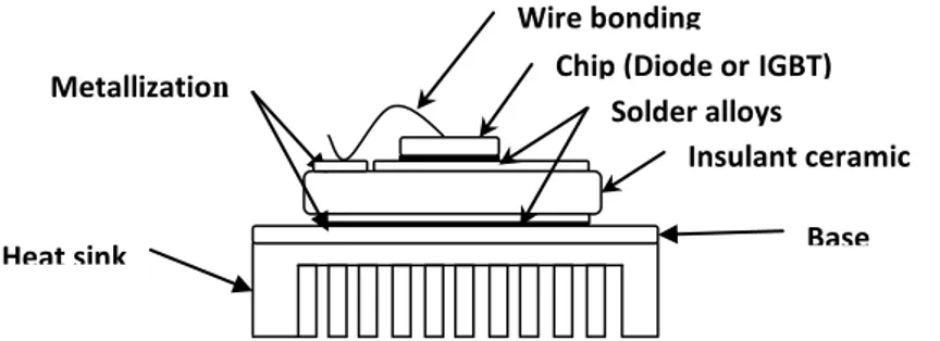
Nowadays, electronic power modules give promising perspectives for entirely electric engines with less fuel-dependent systems in aeronautic industry. Typical power module is composed of three major components: a semi-conductor chip which may be an IGBT and/or a diode, a metalized ceramic substrate and a base plate. These components are soldered to each other’s and positioned over a heat sink for thermal management (Fig .1). The dielectric ceramic substrate is double bonded with thick copper or aluminum metallization for improving heat spreading. The base plate is made also of high thermally conductive material such as AlSiC, copper or aluminum. The brazing is achieved using solder alloys considered as one of the principal failure causes in the module due to its weaker thermomechanical properties as compared to the other constitutive materials. So, regardless of their advantages, the design of the electronic power module devices represents a great challenge due to the extreme environmental and operational conditions which involve creep, fatigue as well as creep-fatigue interaction and high thermal variation. The high reliability of such components is then related to the optimized choice of the constitutive materials of the devices which consists basically on the microstructure properties, material compatibility and thermomechanical characteristics. Once the components materials are chosen, the experimental data becomes necessary for the modeling task in order to reproduce the material behavior in its real environmental and assembled state. As indicated earlier, the solder alloy is subjected to a viscoplastic deformation due to high temperature levels; the solder behavior must be described by appropriate viscoplastic models and lifetime prediction rules.
Fig. 1: Internal architecture of a typical electronic power module.
There are in the literature a wide range of models which can be classified within the formulation nature of the constitutive equations i.e. coupled or uncoupled deformations. Uncoupled models are based on the summation between the plastic and creep deformations considering that there is no interaction between them [1]. The plastic deformation follows generally an isotropic-plasticity as Ramberg-Osgood model [2] or also a Drucker-Prager plasticity model [3]. The creep deformation evolves according to a creep model such as Norton [4], Garofalo [5], Darveaux [6],…The uncoupled deformation models are characterized by a simple formulation so they can be easily integrated and identified. In the other side, work-hardened solders show creep-plasticity interaction especially in the case of cyclic loading and thermal variations i.e. high-to-low or low-to-high temperatures. In this case, some kinds of unified thermoelastoviscoplastic models which consider that the plasticity and creep effects may be represented by only one time-dependent deformation are suitable for the modeling under complex loading conditions. The concept of state variables is also introduced in these models [7] in order to reproduce some other physical phenomena such as isotropic or kinematic hardening, dynamic and thermal static recovery, ratcheting, aging,… In despite of their complex formulation based on stiff, highly coupled first order differential equations, unified models are frequently used and are more integrated in the finite element codes. Anand’s unified viscoplastic model is usually employed for the deformation modeling of the solder alloys [8-10]. It’s integrated in a uniaxial form and has a unique scalar state variable which represents the resistance to plastic deformation. However, Bauschinger effects and cyclic hardening couldn’t be well described [11].
Other authors such as Krempl, tried to incorporate on its own overstress-based viscoplastic model a kinematic state variable. Busso et al, introduced a stress-dependent Arrhenius term to describe more efficiently the thermal variation effects [12]. Basaran and Chandaroy formulate a dependency of the material viscoplastic behavior with its microstructure changes by introducing a grain size variable [13]. McDowell et al, included in their model temperature rate terms in both isotropic and kinematic hardening variables for the thermomechanical cycling [14]. Thermodynamical restrictions are also demonstrated for thermoplasticity and thermoelastoviscoplasticity cases [15]. Chaboche’s used a power law term to describe the plastic flow and may contains several kinematic and isotropic hardening variables as well as a plastic strain memory for the saturation state [16]. The model proved to be thermodynamically consistent.
McDowell and Chaboche’s viscoplastic models appear to include the most features that the solder joints material can exhibit and to match well with the thermomechanical responses of several materials references [17, 18]. We propose in this framework, (i) a description of the formulation of these unified models (ii) an integration of the first order differential constitutive equations and its implementation in a FE code ABAQUS® (iii) a comparison of the viscoplastic models compared to the experimental data and the numerical simulations.
Formulation of the viscoplastic constitutive equations
The unification of the inelastic deformations and the description of several physical material states are inducing in nature a huge number of material parameters and a coupled set of stiff and first order
Chip (Diode or IGBT) Metallization s Solder alloys Base plate Heat sink Wire bonding Insulant ceramic substrate
differential equations which couldn’t be integrated without accurate and stable numerical methods. It’s the case for the McDowell and Chaboche’s viscoplastic models.
McDowell viscoplastic model. Contrary to Anand’s model based on Garofalo hyperbolic sine function, McDowell’s model contains a Zener-Hollowman exponential parameter with respect to the power law term [19]. The temperature dependency of the model is written as a function of the Arrhenius term in the flow law.
Flow Law
The inelastic strain rate is determined by the following rate equation:
2 3 , , 2 ij ij in ij v ij ij s A F S D J (1) With,
2 v ij ij S J R (2)WhereJ2
ij ij
23
sijij
: sijij
denotes the second invariant of the reducedstress
sijij
. sij is the deviatoric stress tensor, ij the backstress tensor, and is a thermaldiffusivity parameter expressed as an Arrhenius function. A is a temperature independent material parameter. 2 for 1 2 ln 2 exp 2 for exp m m m m T T T T kT Q T T kT Q (3) m
T is the melting temperature, Q the activation energy, and k the Boltzmann’s constant. . is defined as g g
if g 0 else g 0.
The function F is the Zener-Holloman parameter expressed as follows
1
exp N B N F (4) Knowing that
D Sv 1 (5) is a factor which represents the sensibility partition of the strain rate and mainly varied between 0
and 1. D is an isotropic resistance which is usually constant for solder alloys or proportional to the yield stress for copper
D A0R
[20]. N is a temperature-dependent andA temperature-0independent material parameters. In the case of 0, the flow law is expressed as:
1 2 3 exp 2 N N ij ij v v in ij ij ij s S S A B T D D J (6) Evolution equations ij represents the sum of s ij
and *
ij
.
The evolution equations of the state variables s ij
and *
ij
are written in the following forms
s ij s s ij s ij s ij s ij in ij s ij Cb T T b b T C C T b p b C b b C 0 ' ' / / (7)* * * * * * * * ij ij in ij ij H H HT T H (8) Defining
: in
1/2 ij in ij in ij p and s ij ij ij ij s s b . T is the absolute temperature.
We see that the evolution equation is defined as the sum of a hardening term which is proportional to in
ij
, dynamic recovery terms which are proportional to p and T and finally a static thermal recovery term which depends on both T and s
ij
and acts considerably when time-dependent
mechanisms are dominant (creep, relaxation, recovery,…).
The isotropic hardening variable is decomposed into two parts: R corresponds to the variation iso
of the yield stress and biso corresponds to the saturation value of the kinematic hardening
1 2 3 iso R (9) iso b (10)
T T p ' ' (11) is a temperature dependent parameter which represents the saturation value of .
The thermal static recovery terms are expressed in the following forms:
Ms/2 s ij s ij s s C , * *
* *
M*/2 ij ij C ,
M/2 ij ij C The yield stress R and the kinematic hardening saturation b are written respectively as
T RisoR R 0
and bb0
T biso0
R is the initial yield stress. H ,* Cs, M ,s C*, M ,* Cand M are material parameters.
In the case of initially isotropic materials, the stress is written as a function of the total strain and the inelastic strain tensors respectivelyeijandijin
1 2 2 ij in ij ij ij s G s G e T T (12) And
0
1 2 3 3 1 2 3 T T kk E kk kk T E T T T T T (13) T is the coefficient of thermal expansion and T is the reference temperature. In the isothermal 0
loading case, temperature rate terms are not considered.
Chaboche’s viscoplastic model. Thanks to its capability to reproduce a realistic behavior of the
material under complex loading, the Chaboche’s Model becomes one of the most known unified viscoplastic model used usually for thermomechanical fatigue behavior of nickel based superalloys for turbines blades and other materials with high performance [21]. We present here a formulation of the Chaboche’s model with combined kinematic and isotropic hardening variables. The model contains also static thermal recovery terms.
Flow Law
The inelastic strain rate is determined as follows
0 2 2 3 2 n ij ij ij ij in ij ij ij J R R s D J (14)Let’s see that F takes the formF Nknowing that
0 2 v ij ij S J R R and D Sv Evolution equationsThe evolution equations of the state variables s ij
and *
ij
are written in the following forms
s in s s s ij Cb ij C pij ij (15) * * * * * ij ij in ij ij H H p (16)
H is a temperature dependent material parameter.
For the isotropic hardening equations, R corresponds tothus, for notations equivalence, we can write adopt equation (11) as the equation of evolution of the isotropic hardening variable R.
Integration and implementation
Time integration of the constitutive equations. Due to the strong coupling of the first order
differential equations in the two models, a great care must be taken for the choice of the appropriate integration algorithm. The method must show a good accuracy and approved stability. Thus, satisfying numerical results may be obtained when semi-implicit Euler method is used with a Newton-Raphson iteration scheme [20] or when a fully implicit Euler method is combined with Regula Falsi (Pegasus method) and fixed point iteration schemes [22]. So, we’ve adopted these methods respectively for McDowell’s and Chaboche’s models. Let’s just remember that for the Euler method and for a first order differential equation such as,yij f y t
ij, , the unknown function y(t) can be calculated knowing that :
t t t
ij t y y
y
1 (17)
For a fully implicit Euler scheme,is equal to 1. So, the incremental solution depends on the evaluated quantities at t + Δt. In the semi-implicit Euler scheme, all the incremental forms of the state variables and stress are expressed with respect to the known variables at t, such as
t dt t t t
ij ij ij ij t
y y y y ty
(18)
But the incremental cumulated inelastic deformationpis expressed as function of the calculated variables at t + dt and the aim is to obtain
, ,
in t dt: in t dt 0 ij ij F R p t (19) As indicated before,
in t dt ij is calculated using the variable at time t + dt. For McDowell’s model, the variablepis updated by Newton-Raphson scheme as follows
1 , , , ' , , , ij ij k k ij ij F p R p p F p R (20) As a result, if 1 1 k k tol k p p p , the solution is then retained else the calculation is repeated for the
next iteration step k + 1. In this exercise, tolis equal to 10-4.
In spite of the lack on the predefined viscoplastic models available in Abaqus®, this software offers to the user the possibility to work with its own deformation behavior model. The integration algorithms for both Chaboche’s and McDowell’s viscoplastic models are then coded in FORTRAN language and implemented as UMAT subroutine formats. In the FE code, an asymmetric solver is used with a full newton-Raphson iteration scheme for finite element computations. This is due to the asymmetric aspect of the jacobian matrix in both two models.
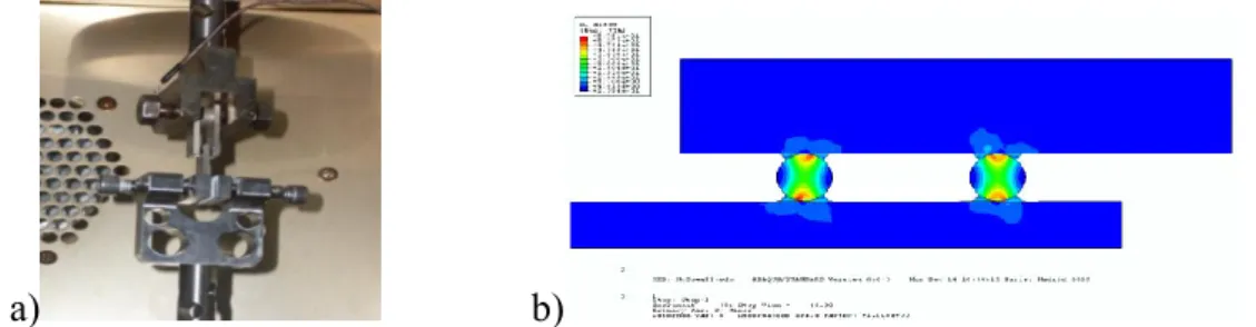
Identification of the material parameters. Cyclic and asymmetric displacement controlled tests
are performed at 50°C, 125°C and 180°C under various displacement rates 2, 3 and 10-4mm/s. Creep tests are also achieved at 180°C and 125°C with respectively 120 N and 180 N. The
shear specimen considered (fig. 2(a)) consists of three Ni coated copper plates which are connected to each other by means of copper bumps. The copper bumps are brazed to the plates using a SnAgCu solder alloy. This specimen is designed to be mounted on an Electroforce® machine test, which is rated up to 450 N and can perform precision materials tests including tension/compression loading, fatigue and dynamic material characterization. The apparatus is equipped with a furnace which can reach temperatures up to 300°C. Displacements are measured by means of an axial extensometer
a) b)
Fig. 2: Shear specimen used for identification procedure (a) experimental configuration (b) corresponding FE model.
Thermal properties
Thermal conductivity λ (W/m.K) 33 Density ρ (Kg/mm3) 7.36×10⁻⁶ Specific heat Cp (J.K-1) 200 Coefficient of thermal expansion α (ppm/K) 3×10⁻⁵
Table1: Thermal properties for SnAgCu.
McDowell’s Model parameters Chaboche’s Model parameters
Temperature 25°C 125°C 180°C Temperature 25°C 125°C 180°C n 3 - - R0(MPa) 12 5 4.15 A 5000 - - C 410.5 230 76 B 0.001 - - b(MPa) 5 5.21 5.71 C 250 274 287 H*(MPa) 1200 1114.1 923 D(MPa) 4 - - H 96 83.2 68.1 H*(MPa) 64 87 99.2 Cs(s-1MPa1-Ms) 5×10⁻⁴ 7.4×10⁻⁴ 1.2×10⁻³ w 0.5 - - C*(s-1MPa1-Ms) 3×10⁻² 5.9×10⁻² 6×10⁻² Cs 0.079 - - Ms 3.5 3.9 3.9 C*(MPa/s) 600 - - M* 1.4 1.75 1.2 Ms 5 - - 224 176 149 M* 5 - - μ' 7.3 7.6 8.7 Q(J/mol) 27000 - - R0(MPa) 12 5 1.5 b0(MPa) 8.3 7.2 6 150 75 38 μ' 6 6.5 9.3
Table2: Identified material parameters for the SnAgCu.
The Least square procedure for the parametric identification was applied as a Python script in combination with the FE code Abaqus® and the UMAT subroutine. The figure 2(b) shows a half symmetric model of the specimen considered in the finite element computations.
Copper plates are considered as an elastoplastic material modeled with a combined hardening elastoplastic Chaboche model. Elastic modulus and Poisson ratio of SnAgCu are taken respectively
as E (MPa) = 41632 - 19.4 T (°C) and v = 0.33. Thermal properties of the solder are given in table 1. The identified material parameters of the SnAgCu solder alloy are given in the table 2 for Chaboche’s and McDowell’s models.
Contrarily to the Chaboche’s model where all parameters are temperature-dependent, McDowell model contains only six temperature-dependent coefficients i.e. E, v, C, H*, b0, R0, μ' andχ . All the temperature dependent parameters may be expressed as functions of temperature.
Numerical results and discussions. Experimental displacement profiles are used in the FE code as
imposed loading to extract the SnAgCu mechanical responses. Following all the displacement imposed profiles, the displacement rate is not constant during the tests and varies from 10-2 to 10-5 mm/s.
a) b)
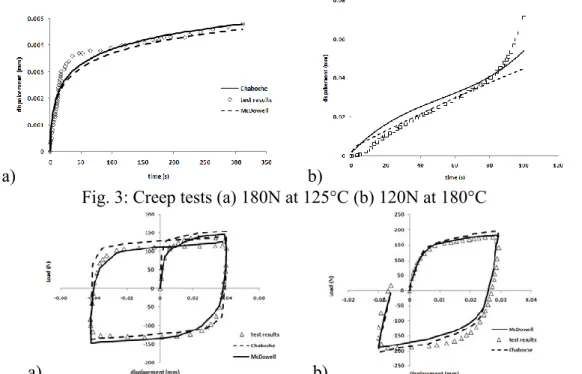
Fig. 3: Creep tests (a) 180N at 125°C (b) 120N at 180°C
a) b)
Fig. 4: Displacement controlled tests (a) Symmetric 10-2mm/s at 180°C (b) Asymmetric 10-3mm/s at 125°C.
Figure 3 shows the evolution of the displacement as a function of the time for different creep tests at 125 and 180°C. The two identified laws are in good agreement with the experimental data. For more complex cyclic loading, we can see the load-displacement curves (figures 4), where the assembled specimen tends to softens under. It saturates quickly whatever the imposed displacement rate but keep a nearly constant hardening behavior. Viscoplastic behavior of SnAgCu doesn’t vary so much and still stable even when temperature changes.
Moreover, in low temperature ranges and in comparison with McDowell’s model, Chaboche’s model appears to fit well the asymmetric data at 25°C in spite of the error at the end of loading. But at high temperatures, numerical results from McDowell’s model correlate well with experimental data at 125°C and 180°C which is approved by the use of an activation energy term. In fact, this term intervenes in the flow and the evolution equations as well which is not the case in the Chaboche’s model.
Summary
Thermoviscoplastic behavior of a lead-free solder SnAgCu is characterized using several mechanical tests at three different temperatures. The mechanical responses are used to identify two unified viscoplastic models. Numerical results of the viscoplastic models show mainly good correlation with experimental data especially at high temperature, when recovery terms dominate. In the high temperature range, the use of activation energy term appears to produce more accurate
results but this fact had to be verified by thermomechanical fatigue tests when the influence of temperature rate is not negligible too. Also, SnAgCu cyclic behavior must be investigated using fatigue tests to understand the softening behavior and to quantify the damage in the material for the lifetime prediction as well.
References
[1] K. Ohguchi, K. Sasaki, JSME International Journal 46 (2003) 559-566. [2] X. Chen, J.Song, K.S.Kim, Int. J. Fatigue 28 (2005) 767–776.
[3] S. C. Desai, R. Whitenack, J. Electronic Packaging 123 (2001) 19-33. [4] X. J. Yang, C. L. Chow, K. J. Laub, Int. J. Fatigue 25 (2003) 533-546. [5] H. Ma, J Mater Sci, 44 (2009) 3841–3851.
[6] R. Darveaux, K. Banerji, IEEE Transactions on CHMT, 15 (1992) 1013–1024.
[7] K. Krausz, Unified constitutive laws of plastic deformation, Edited by A.S.Krausz and K.Krausz 1996.
[8] Qu, P. M. Constitutive Modeling of Lead-Free Solders, IEEE Transaction (2005). [9] Hua Ye, Finite Elements in Analysis and Design, 38 (2002) 601–612.
[10] D. Yu, X. Chen, G. Chen, G. Lu, Z. Wang, Materials and Design, 30 (2009) 4574–4579. [11] J. Gomez, C. Basaran, Mechanics of Materials, 38 (2006) 585–598.
[12] S. Wen, L.M. Keer, H. Mavoori, Journal of Electronic Materials, 30 (2001) 1190-1196. [13] R.W. Neu, D.T. Scott, M.W. Woodmansee, Int. J. Plasticity 16 (2000) 283-301.
[14] D. L. Mcdowell, International Journal of Plasticity, 8 (1992) 685-728. [15] J.L. Chaboche, G. Rousselier, J Press Vessel Tech 9 (1983)105-153.
[16] J. Lemaitre, J.L. Chaboche. Mechanics of solid materials, Cambridge University Press(1998). [17] J. C. Moosbrugger, D. L. Mcdowell, J. Mech. Phys. Solids, 38 (1990) 627-656.
[18] P. Chellapandi, S.C. Chetal, S.B. Bhoje, Transaction of the 14th International Conference on Structural Mechanics in Reactor Technology (1997) 173-180.
[19] V. Stolkarts, L.M. Keer, M.E. Fine, J. Electronic Packaging 123 (2001) 351-355. [20] C. Fu, D.L. McDowell, I.C. Ume, J. Electronic Packaging 120 (1998) 24-34.
[21] P. Almroth, M. Hasselqvist, K. Simonsson, S. Sjöström, Computational Materials Science, 29 (2004) 437-445.