HAL Id: inria-00350600
https://hal.inria.fr/inria-00350600
Submitted on 7 Jan 2009
HAL is a multi-disciplinary open access
archive for the deposit and dissemination of
sci-entific research documents, whether they are
pub-lished or not. The documents may come from
teaching and research institutions in France or
abroad, or from public or private research centers.
L’archive ouverte pluridisciplinaire HAL, est
destinée au dépôt et à la diffusion de documents
scientifiques de niveau recherche, publiés ou non,
émanant des établissements d’enseignement et de
recherche français ou étrangers, des laboratoires
publics ou privés.
A framework for scalable vision-only navigation
S. Segvic, A. Remazeilles, A. Diosi, François Chaumette
To cite this version:
S. Segvic, A. Remazeilles, A. Diosi, François Chaumette. A framework for scalable vision-only
nav-igation. Advanced Concepts for Intelligent Vision Systems, ACIVS’07, 2007, Delft, Netherlands.
pp.112-124. �inria-00350600�
A framework for scalable vision-only navigation
⋆ Siniˇsa ˇSegvi´c, Anthony Remazeilles, Albert Diosi and Fran¸cois ChaumetteINRIA/IRISA, Campus de Beaulieu, F-35042 Rennes Cedex, France
Abstract. This paper presents a monocular vision framework enabling feature-oriented appearance-based navigation in large outdoor environ-ments containing other moving objects. The framework is based on a hybrid topological-geometrical environment representation, constructed from a learning sequence acquired during a robot motion under hu-man control. The framework achieves the desired navigation functional-ity without requiring a global geometrical consistency of the underlying environment representation. The main advantages with respect to con-ventional alternatives are unlimited scalability, real-time mapping and effortless dealing with interconnected environments once the loops have been properly detected. The framework has been validated in demanding, cluttered and interconnected environments, under different imaging con-ditions. The experiments have been performed on many long sequences acquired from moving cars, as well as in real-time large-scale navigation trials relying exclusively on a single perspective camera. The obtained results imply that a globally consistent geometric environment model is not mandatory for successful vision-based outdoor navigation.
1
Introduction
The design of an autonomous mobile robot requires establishing a close rela-tion between the perceived environment and the commands sent to the low-level controller. This necessitates complex spatial reasoning relying on some kind of in-ternal environment representation [1]. In the mainstream model-based approach, a monolithic environment-centred representation is used to store the landmarks and the descriptions of the corresponding image features. The considered fea-tures are usually geometric primitives, while their positions are expressed in coordinates of the common environment-wide frame [2, 3]. During the naviga-tion, the detected features are associated with the elements of the model, in order to localize the robot, and to locate previously unobserved model elements. However, the success of such approach depends directly on the accuracy of the underlying model. This poses a strong assumption which impairs the scalability and, depending on the input, may not be attainable at all.
The alternative appearance-based approach employs a sensor-centred repre-sentation of the environment, which is usually a multidimensional array of sensor readings. In the context of computer vision, the representation includes a set of
⋆
This work has been supported by the French national project Predit Mobivip, by the project Robea Bodega, and by the European MC IIF project AViCMaL.
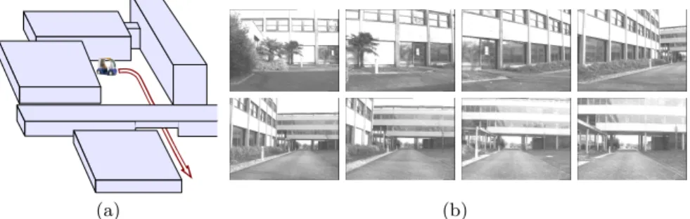
key-images which are acquired during a learning stage and organized within a graph [4]. Nodes of the graph correspond to key-images, while the arcs link the images containing a required number of common landmarks. This is illustrated in Figure 1. The navigation between two neighbouring nodes is performed using
(a) (b)
Fig. 1.Appearance-based navigation: the sketch of a navigation task (a), and the set of first eight images from the environment representation forming a linear graph (b). Note that the graph has been constructed automatically, as described in 3.1.
well developed techniques from the field of mobile robot control [5]. Different types of landmark representations have been considered in the literature, from the integral contents of a considered image [6] and global image descriptors [4], to more conventional point features such as Harris corners [2, 7]. We consider the latter feature-oriented approach, in which the next intermediate key-image is reached by tracking common features from the previous key-image. Here, it is critical to recognize landmarks which recently entered the field of view, or re-gained a normal appearance after occlusion, motion blur or illumination distur-bances. Estimating locations of invisible features (feature prediction) is therefore an essential capability in feature-oriented navigation.
We present a novel framework for scalable mapping and localization, enabling robust appearance-based navigation in large outdoor environments. The frame-work is presented in a broader frame of an envisioned long-term architecture, while more details can be found in [8, 9]. Mapping and navigation are considered separately as an interesting and not completely solved problem. The employed hierarchical environment representation [4, 10] features a graph of key-images at the top, and local 3D reconstructions at the bottom layer. The global topolog-ical representation ensures an outstanding scalability, limits the propagation of association errors and simplifies consistency management in interconnected envi-ronments. On the other hand, the local geometric models enable accurate feature predictions. We strive to obtain the best predictions possible, and favour local over global consistency by avoiding a global environment model. The results of demanding robot control experiments demonstrate that a globally consistent 3D reconstruction is not required for a successful large-scale vision-based navigation. An appearance-based navigation approach with feature prediction has been described in [11]. Simplifying assumptions with respect to the motion of the robot
have been used, while the prediction was implemented using intersection of the two epipolar lines, which has important limitations [12]. The need for feature prediction has been alleviated in [7], where the previously unseen features from the next key-image are introduced using wide-baseline matching [13]. A similar approach has been proposed in the context of omnidirectional vision [14]. In this closely related work, feature prediction based on point transfer [12] has been employed to recover from tracking failures, but not for feature introduction as well. However, wide-baseline matching [14, 7] is prone to association errors due to ambiguous landmarks. In our experiments, substantially better feature introduction has been achieved by exploting the point transfer predictions.
In comparison with model-based navigation approaches such as the one de-scribed in [3], our approach does not require a global consistency. By posing weaker requirements, we increase the robustness of the mapping phase, likely obtain better local consistencies, can close loops regardless of the extent of the accumulated drift and have better chances to survive correspondence errors. Notable advances have been recently achieved in model-based SLAM [15]. Nev-ertheless, current implementations have limitations with respect to the number of mapped points, so that a prior learning step still seems a necessity in realistic navigation tasks. Our approach has no scaling problems: experiments with 15000 landmarks have been performed without any performance degradation.
The paper is organized as follows. The envisioned architecture for vision-based navigation is described in Section 2. Implementation details of the current implementation are described in Section 3. Section 4 provides the experimental results, while the conclusion is given in Section 5.
2
The envisioned architecture
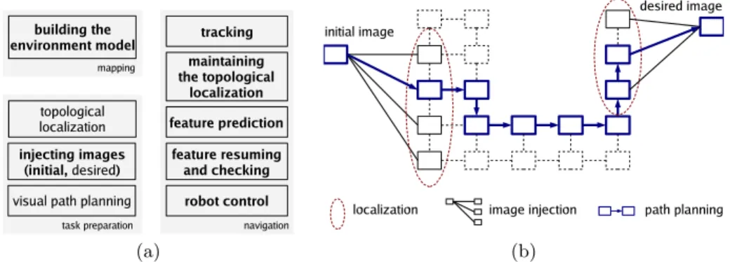
The presented work is an incremental step towards a system for appearance-based navigation in interconnected structured environments, which is a long-term research goal in our laboratory [16]. The desired autonomous system would be capable to autonomously navigate in previously mapped environment, to-wards a goal specifed by a desired goal-image. The devised architecture assumes operation in three distinct phases, as illustrated in Figure 2(a).
The mapping phase creates a topological–geometrical environment represen-tation from a learning sequence acquired during a robot motion under a human control. The key-images are selected from the learning sequence and organized within a graph in which the arcs are defined between nodes sharing a certain number of common features. The matching features in the neighbouring nodes are used to recover a local 3D reconstruction, which is assigned to the corre-sponding arc. These features are considered for tracking whenever the robot arrives close to the viewpoints from which the two key-images were acquired.
The task preparation phase is performed after the navigation task has been presented to the navigation system in the form of a desired goal-image, as illus-trated in Figure 2(b). The initial topological localization corresponds to locating the current and the desired images in the environment graph by content-based
(a) (b)
Fig. 2.The envisioned architecture for feature-oriented appearance-based navigation (a), The entries which are considered and implemented in this work are typeset in bold. The illustration of the three procedures from the task preparation phase (b).
image retrieval [16]. The two images are consequently injected into the graph using the correspondences obtained by wide-baseline matching. Finally, the op-timal topological path is determined using a shortest path algorithm. The nodes of the determined path denote intermediate milestones through which the robot is supposed to navigate towards the desired goal.
The navigation phase involves a visual servoing processing loop [17], in which the point features from images acquired in real-time are associated with their counterparts in the key-images. Thus, two distinct kinds of localization are re-quired: (i) explicit topological localization, and (ii) implicit fine-level localization through the locations of the tracked landmarks. Topological location corresponds to the arc of the environment graph incident to the two key-images having most content in common with the current image. It is extremely important to main-taining an accurate topological location as the navigation proceeds, since that defines the landmarks considered for localization. During the motion, the track-ing may fail due to occlusions, motion blur, illumination effects or noise. Feature prediction allows to deal with this problem and resume the feature tracking on the fly while minimizing the chances for correspondence errors.
3
Scalable mapping and localization
In the broader context presented in Section 2, we mainly address the mapping and the navigation phase, which have been implemented within the mapping and localization components of the framework.
Both components rely on feature tracking and two-view geometry. The de-vised multi-scale differential tracker with warp correction and checking provides correspondences with few outliers. Bad tracks are identified by a threshold R on RMS residual between the warped current feature and the reference appearance. The employed warp includes isotropic scaling and affine contrast compensation [18]. The two-view geometry is recovered in a calibrated context by random sampling, with the five-point algorithm [19] as the hypothesis generator.
For simplicity, the actual implementation allows only linear or circular topo-logical representations. This obviates the need for the localization and planning procedures, which we have addressed previously [16]. The resulting implementa-tion of the task preparaimplementa-tion phase is described along the localizaimplementa-tion component. 3.1 The mapping component
The mapping component constructs a linear environment graph and annotates its nodes and arcs with precomputed information. The nodes of the graph are formed by choosing the set of key-images Ii. The same indexing is used for arcs
as well, by defining that arc i connects nodes i − 1 and i (cf. Figure 3). If the graph is circular, arc 0 connects the last node n − 1 with the node 0. Each node is assigned the set Xiof features from Ii, denoted by distinctive identifiers. Each
arc is assigned an array of identifiers Midenoting landmarks located in the two
incident key-images, and annotated with the recovered two-view geometries Wi.
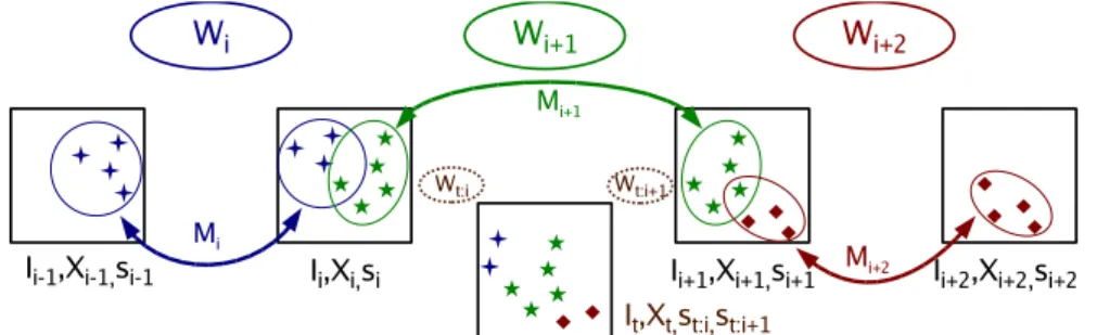
Fig. 3.The linear environment graph. Nodes contain images Ii, extracted features Xi
and scale factors si. Arcs contain match arrays Mi and the two-view geometries Wi.
The figure also shows the current image It, which is considered in 3.2. If the topological
location is i + 1, the features considered for tracking belong to Wi, Wi+1 and Wi+2.
The elements of Wiinclude motion parameters Riand ti(|ti| = 1), and
met-ric landmark reconstructions Qi. The two-view geometries Wi are deliberately
not put into an environment-wide frame, since contradicting scale sequences can be obtained along the graph cycles. The scale ratio si between the incident
ge-ometries Wi and Wi+1 is therefore stored in the common node i. Neighbouring
pairs of geometries Wi+1 and Wi+2 need to have some features in common,
Mi+1∩ Mi+2 6= ∅, in order to enable the transfer of features from the next
two key-images (Ii+1, Ii+2) on the path (cf. 3.2). Quantitatively, a particular arc
of the map can be evaluated by the number of correspondences |Mi| and the
estimate of the reprojection error σ(Wi) [12]. Different maps of the same
envi-ronment can be evaluated by the total count of arcs in the graph |{Mi}|, and by
the parameters of the individual arcs |Mi| and σ(Wi). It is usually favourable to
have less arcs, since that ensures a smaller difference in lines of sight between the relevant key-images and the images acquired during navigation.
The devised mapping solution uses the tracker to find the stablest point fea-tures in a given subrange of the learning sequence. The tracker is initiated with all Harris points in the initial frame of the subrange. The features are tracked until the reconstruction error between the first and the current frame of the sub-range rises above a predefined threshold σ. Then the current frame is discarded, while the previous frame is registered as the new node of the graph, and the whole procedure is repeated from there. This is similar to visual odometry [20], except that we employ larger feature windows and more involved tracking [18] in order to achieve more distinctive features and longer feature lifetimes. To ensure a minimum number of features within an arc of the graph, a new node is forced when the absolute number of tracked points falls below n.
The above matching scheme can be complemented by wide-baseline matching [13] when there are discontinuities in the learning sequence caused by a large moving object, or a “frame gap” due to bad acquisition. Such events are reflected by a general tracking failure in the second frame of a new subrange.
Wide-baseline matching is also useful for connecting a cycle in the environ-ment graph. To test whether the learning sequence is acquired along a circular physical path, the first and the last key-image are subjected to matching: a cir-cular graph is created on success, and a simple linear graph otherwise. In case of a monolithic geometric model, the loop closing process would need to be fol-lowed by a sophisticated map correction procedure, in order to try to correct the accumulated error. Due to topological representation at the top-level, this operation proceeds reliably and smoothly, regardless of the extent of the drift. 3.2 The localization component
In the proposed framework, the tracked features belong either to the actual arc (topological location), or the two neighbouring arcs as illustrated in Fig-ure 3. We focus on on-line facets of the localization problem: (i) robust fine-level localization relying on feature prediction, and (ii) maintenance of the topologi-cal location as the navigation proceeds. Nevertheless, for completeness, we first present a minimalistic initialization procedure used in the experiments.
The initialization procedure The navigation program is started with the following parameters: (i) map of the environment, (ii) initial topological location of the robot (index of the actual arc), and (iii) calibration parameters of the attached camera. This is immediately followed by wide-baseline matching [13] of the current image with the two key-images incident to the actual arc. From the obtained correspondences, the pose is recovered in the actual geometric frame, allowing to project the mapped features and to bootstrap the processing loop. Feature prediction and tracking resumption The point features tracked in the current image It are employed to estimate the current two-view geometries
Wt:i(Ii, It) and Wt:i+1(Ii+1, It) towards the two incident key-images, using the
geometry is devised by a decomposed approach related to [21]. The approach relies on recovering the relative scale between the two independently recovered metric frames, by enforcing the consistency of the common structure. The main advantages with respect to the “golden standard” method [12] are the utilization of pairwise correspondences (which is of particular interest for forward motion), and real-time performance. Thus, the three-view geometry (It, Ii, Ii+1) is
recov-ered by adjusting the precomputed two-view geometry Wi+1 towards the more
accurate (in terms of reprojection error) of Wt:iand Wt:i+1(see Figure 3). The
geometry (It, Ii+1, Ii+2) is recovered from Wi+2 and Wt:i+1, while (It, Ii−1, Ii)
is recovered from Wi and Wt:i. Current image locations of landmarks mapped
in the actual arc i + 1 are predicted by the geometry (It, Ii, Ii+1). Landmarks
from the previous arc i and the next arc i + 2 are transferred by geometries (It, Ii−1, Ii) and (It, Ii+1, Ii+2), respectively.
Point transfer is performed only if the estimated reprojection error of the employed current geometry is within the safety limits. The predictions are refined (or rejected) by minimizing the residual between the warped current feature and the reference appearance. As in tracking, the result is accepted if the procedure converges near the predicted location, with an acceptable residual. An analogous procedure is employed to check the consistency of the tracked features, which occasionally “jump” to the occluding foreground.
Maintaining the topological location Maintaining a correct topological lo-cation is critical in sharp turns where the tracked features die quickly due to the contact with the image border. An incorrect topological location implies a suboptimal introduction of new features and may be followed by a failure due to insufficient features for calculating Wt:i and Wt:i+1. Best results have been
ob-tained using a geometric criterion: a transition is taken when the reconstructed camera location overtakes the next key-image Ii+1. This can be expressed as
h−Ri+1⊤· ti+1, tt:i+1i < 0 . The decision is based on the geometry related to
the next key-image Wt:i+1, which is geometrically closer to the hypothesized
transition. Backwards transitions can be analogously defined in order to support reverse motion of the robot. After each transition, the reference appearances (references) are redefined for all relevant features in order to achieve better tracking. For a forward transition, references for the features from the actual geometry Wi+1 are taken from Ii+1, while the references for the features from
Wi+2 are taken from Ii+2 (cf. Figure 3). Previously tracked points from
geome-tries Wi+1 and Wi+2 are instantly resumed using their previous positions and
new references, while the features from Wi are discontinued.
4
Experimental results
The performed experiments include mapping, off-line localization, and naviga-tion (real-time localizanaviga-tion and control). Off-line sequences and real-time images have been acquired of the robotic car Cycab under human and automatic control.
4.1 Mapping experiments
We first present quantitative mapping results obtained on the learning sequence
ifsic5, corresponding to the reverse of the path shown in Figure 1(a). The
analysis was performed in terms of the geometric model parameters introduced in 3.1: (i) |Mi| (ii) σ(Wi), and (iii) |{Mi}|. Figure 4(a) shows the variation of
|Mi| and σ(Wi) along the arcs of the created environment graph.
A qualitative illustration of the inter-node distance (and |{Mi}|) is presented
in Figure 4(b) as the sequence of recovered key-image poses (common global scale has been enforced for visualisation purposes). The figure suggests that the map-ping component adapts the density of key-images to the inherent difficulty of the scene. The dense nodes 7-14 correspond to the first difficult moment of the learning sequence: approaching the traverse building and passing underneath it. Nodes 20 to 25 correspond to the sharp left turn, while passing very close to a building. The hard conditions persisted after the turn due to large feature-less bushes and a reflecting glass surface: this is reflected in dense nodes 26-28, cf. Figure 4(c). The number of features in arc 20 is exceptionally high, while the incident nodes 19 and 20 are very close. The anomaly is due a large frame gap causing most feature tracks to terminate instantly. Wide-baseline matching succeeded to relate the key-image 19 and its immediate successor which conse-quently became key-image 20. The error peak in arc 21 is caused by an another gap which has been successfully bridged by the tracker alone.
0 2 4 6 8 10 0 5 10 15 20 25 0 50 100 150 200 stdev npoints index stdev npoints 0 1 2 3 456 78 910111213 14 15 16 17 181920212223 24 25 26 2728 (a) (b) (c)
Fig. 4.The mapping results on the sequenceifsic5containing 1900 images acquired along a 150 m path: counts of mapped point features |Mi| and reprojection errors σ(Wi)(a), the reconstructed sequence of camera poses (b), and the 28 resulting key-images (c).
The second group of experiments, concerns the learning sequencelooptaken
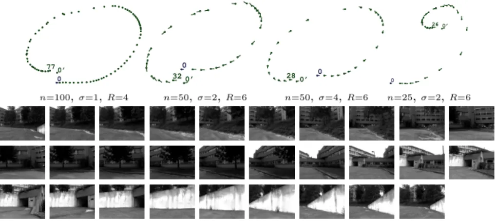
along a circular path of approximately 50 m. We investigate the sensitivity of the mapping algorithm with respect to the three main parameters described in 3.1: (i) minimum count of features n, (ii) maximum allowed reprojection error σ, and (iii) the RMS residual threshold R. The reconstructions obtained for 4
different parameter triples are presented in Figure 5. The presence of node 0’ indicates that the cycle at the topological level has been successfully closed by wide-baseline matching. Ideally, nodes 0’ and 0 should be very close; the extent of the distance indicates the magnitude of the error due to the accumulated drift. Reasonable and usable representations have been obtained in all cases, despite the smooth planar surfaces and vegetation which are visible in Figure 5(bottom). The experiments show that there is a direct coupling between the number of arcs |{Mi}| and the number of mapped features |Mi|. Thus, it is beneficial to seek the
smallest |{Mi}| ensuring acceptable values for σ(Wi) and |Mi|. The last map in
Figure 5 (top-right) was deliberately constructed using suboptimal parameters, to show that our approach essentially works even in cases in which enforcing the global consistency is difficult. The navigation can smoothly proceed despite a discontinuity in the global geometric reconstruction, since the local geometries are “elastically” glued together by the continuous topological representation.
0 77 0’ 0 32 0’ 0 28 0’ 0 26 0’ n=100,σ=1,R=4 n=50,σ=2,R=6 n=50,σ=4,R=6 n=25,σ=2,R=6
Fig. 5.Reconstructed poses obtained on sequence loop, for different sets of mapping parameters (top). Actual key-images of the map obtained for n = 50, σ = 4, R = 6 (bottom). This map will be employed in localization experiments.
4.2 Localization experiments
In the localization experiments, we measure quantitative success in recogniz-ing the mapped features. The results are summarized in Figure 6, where the counts of tracked features are plotted against the arcs of the employed map. We first present the results of performing the localization on two navigation sequences obtained for similar robot motion but under different illumination. Figure 6(a) shows that the proposed feature prediction scheme enables large scale appearance-based navigation, as far as pure geometry is concerned. Fig-ure 6(b) shows that useful results can be obtained even under different lighting conditions, when the feature loss at times exceed 50%.
10 20 30 40 50 60 70 80 90 0 5 10 15 20 25 Total points Tracked max Tracked avg 10 20 30 40 50 60 70 80 90 0 5 10 15 20 25 Total points Tracked max Tracked avg 0 10 20 30 40 50 60 70 80 0 5 10 15 20 25
Avg tracked 1st round Avg tracked 2nd round
(a) (b) (c)
Fig. 6. Quantitative localization results: processing ifsic5 (a) and ifsic1 (b) on a map built on ifsic5, and using the map from Figure 5 over two rounds of loop (c).
The capability of the localization component to traverse cyclic maps was tested on a sequence obtained for two rounds roughly along the same circular physical path. This is a quite difficult scenario since it requires continuous and fast introduction of new features due to persistent changes of viewing direction. The first round was used for mapping (this is the sequence loop, discussed in
Figure 5), while the localization is performed along the combined sequence, in-volving two complete rounds. During the acquisition, the robot was manually driven so that the two trajectories were more than 1 m apart at several occa-sions during the experiment. Nevertheless, the localization was successful in both rounds, as summarised in Figure 6(c). All features have been successfully located during the first round, while the outcome in the second round depends on the extent of the divergence between the two trajectories.
4.3 Navigation experiments
In the navigation experiments, the Cycab was controlled in real-time by visual servoing. The steering angle ψ has been determined from average x components of the current feature locations (xt, yt) ∈ Xt, and their correspondences in the
next key-image (x∗, y∗) ∈ X
i+1: ψ = −λ (xt− x∗) , where λ ∈ R+. One of the
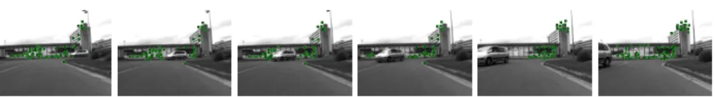
large-scale navigation experiments involved a reference path of approximately 750 m, offering a variety of driving conditions including narrow sections, slopes and driving under a building. An earlier version of the program has been used allowing a control frequency of about 1 Hz. The navigation speed was set ac-cordingly to 30 cm/s in turns, and otherwise 80 cm/s. The map was built on a learning sequence previously acquired under manual control. The robot smoothly completed the path despite a passing car occluding the majority of the features, as shown in Figure 7. Several similar encounters with pedestrians have been processed in a graceful manner too. The system succeeded to map features (and subsequently to find them) in seemingly featureless areas where the road and the grass occupied most of the field of view. The employed environment representa-tion is not very accurate from the global point of view. Nevertheless, the system succeeds to perform large autonomous displacements, while also being robust to other moving objects. We consider this as a strong indication of the forthcoming potential towards real applications of vision-based autonomous vehicles.
Fig. 7.Images obtained during the execution of a navigation experiment. The points used for navigation re-appear after being occluded and disoccluded by a moving car.
5
Conclusion
The paper described a novel framework for large-scale mapping and localization, based on point features mapped during a learning session. The purpose of the framework is to provide 2D image measurements for appearance-based naviga-tion. The tracking of temporarily occluded and previously unseen features can be (re-)started on-the-fly due to feature prediction based on point transfer. 2D navigation and 3D prediction smoothly interact through a hierarchical environ-ment representation. The navigation is concerned with the upper topological level, while the prediction is performed within the lower, geometrical level.
In comparison with the mainstream approach involving a monolithic geomet-ric representation, the proposed framework enables robust large-scale navigation without requiring a geometrically consistent global view of the environment. This point has been demonstrated in the experiment with a circular path, in which the navigation bridges the first and the last node of the topology regardless of the extent of the accumulated error in the global 3D reconstruction. Thus, the proposed framework is applicable even in interconnected environments, where a global consistency may be difficult to enforce.
The localization component requires imaging and navigation conditions such that enough of the mapped landmarks have recognizable appearances in the acquired current images. The performed experiments suggest that this can be achieved even with very small images, for moderate-to-large changes in imaging conditions. The difficult situations include featureless areas (smooth buildings, vegetation, pavement), photometric variations (strong shadows and reflections), and the deviations from the reference path used to perform the mapping, due to control errors or obstacle avoidance.
In the current implementation, the mapping and localization throughput on 320 × 240 gray–level images is 5 Hz and 7 Hz, respectively, using a notebook computer with a CPU roughly equivalent to a Pentium 4 at 2GHz. Most of the processing time is spent within the point feature tracker, which uses a three-level image pyramid in order to be able to deal with large feature motion in turns. The computational complexity is an important issue: with more processing power we could deal with larger images and map more features, which would result in even greater robustness. Nevertheless, encouraging results in real-time autonomous robot control have been obtained even on very small images. In the light of future increase in processing performance, this suggests that the time of vision-based autonomous transportation systems is getting close.
References
1. DeSouza, G.N., Kak, A.C.: Vision for mobile robot navigation: a survey. IEEE Trans. PAMI 24(2) (2002)
2. Burschka, D., Hager, G.D.: Vision-based control of mobile robots. In: Proc. of ICRA, Seoul, South Korea (2001) 1707–1713
3. Royer, E., Lhuillier, M., Dhome, M., Chateau, T.: Localization in urban envi-ronments: Monocular vision compared to a differential GPS sensor. In: Proc. of CVPR. Volume 2., Washington, DC (2005) 114–121
4. Gaspar, J., Santos-Victor, J.: Vision-based navigation and environmental represen-tations with an omni-directionnal camera. IEEE Trans. RA 16(6) (2000) 890–898 5. Samson, C.: Control of chained systems: application to path following and
time-varying point stabilization. IEEE Trans. AC 40(1) (1995) 64–77
6. Matsumoto, Y., Inaba, M., Inoue, H.: Exploration and navigation in corridor environment based on omni-view sequence. In: Proc. of IROS, Takamatsu, Japan (2000) 1505–1510
7. Chen, Z., Birchfield, S.T.: Qualitative vision-based mobile robot navigation. In: Proc. of ICRA, Orlando, Florida (2006) 2686–2692
8. ˇSegvi´c, S., Remazeilles, A., Diosi, A., Chaumette, F.: Large scale vision based navi-gation without an accurate global reconstruction. In: Proc. of CVPR, Minneapolis, Minnesota (2007)
9. Di´osi, A., Remazeilles, A., ˇSegvi´c, S., Chaumette, F.: Experimental evaluation of an urban visual path following framework. In: Proc. of IFAC Symposium on IAV, Toulouse, France (2007)
10. Bosse, M., Newman, P., Leonard, J., Soika, M., Feiten, W., Teller, S.: An ATLAS framework for scalable mapping. In: Proc. of ICRA, Taiwan (2003) 1899–1906 11. Hager, G.D., Kriegman, D.J., Georghiades, A.S., Ben-Shalar, O.: Toward
domain-independent navigation: dynamic vision and control. In: Proc. of ICDC, Tampa, Florida (1998) 1040–1046
12. Hartley, R.I., Zisserman, A.: Multiple View Geometry in Computer Vision. Cam-bridge University Press, CamCam-bridge, UK (2004)
13. Mikolajczyk, K., Schmid, C.: Scale and affine invariant interest point detectors. Int. J. Comput. Vis. 60(1) (2004) 63–86
14. Goedem´e, T., Nuttin, M., Tuytelaars, T., Gool, L.V.: Omnidirectional vision based topological navigation. Int. J. Comput. Vis. (2007) to appear.
15. Davison, A.: Real-time simultaneous localisation and mapping with a single cam-era. In: Proc. of ICCV, Nice, France (2003) 1403–1410
16. Remazeilles, A., Chaumette, F., Gros, P.: 3D navigation based on a visual memory. In: Proc. of ICRA, Orlando, Florida (2006) 2719–2725
17. Chaumette, F., Hutchinson, S.: Visual servo control, part I: Basic approaches. IEEE Robotics and Automation magazine 13(4) (2006) 82–90
18. ˇSegvi´c, S., Remazeilles, A., Chaumette, F.: Enhancing the point feature tracker by adaptive modelling of the feature support. In: Proc. of ECCV, Graz, Austria (2006) 112–124
19. Nist´er, D.: An efficient solution to the five-point relative pose problem. IEEE Trans. PAMI 26(6) (2004) 756–770
20. Nist´er, D., Naroditsky, O., Bergen, J.: Visual odometry. In: Proc. of CVPR, Wash-ington, DC (2004) 652–659
21. Lourakis, M., Argyros, A.: Fast trifocal tensor estimation using virtual parallax. In: Proc. of ICIP, Genoa, Italy (2005) 169–172