HAL Id: hal-01899488
https://hal.archives-ouvertes.fr/hal-01899488
Submitted on 19 Oct 2018
HAL is a multi-disciplinary open access
archive for the deposit and dissemination of
sci-entific research documents, whether they are
pub-lished or not. The documents may come from
teaching and research institutions in France or
abroad, or from public or private research centers.
L’archive ouverte pluridisciplinaire HAL, est
destinée au dépôt et à la diffusion de documents
scientifiques de niveau recherche, publiés ou non,
émanant des établissements d’enseignement et de
recherche français ou étrangers, des laboratoires
publics ou privés.
A new PWM method for a 3-phase 4-leg inverter based
on the injection of the opposite median reference voltage
Abdelkader Bouarfa, Maurice Fadel, Marc Bodson
To cite this version:
Abdelkader Bouarfa, Maurice Fadel, Marc Bodson. A new PWM method for a 3-phase 4-leg inverter
based on the injection of the opposite median reference voltage. 2016 International Symposium on
Power Electronics, Electrical Drives, Automation and Motion (SPEEDAM), Jun 2016, Anacapri, Italy.
�10.1109/SPEEDAM.2016.7525959�. �hal-01899488�
A new PWM method for a 3-phase 4-leg inverter
based on the injection of the opposite median
reference voltage
Abdelkader Bouarfa, Maurice Fadel
LAPLACE
Université de Toulouse, CNRS, INPT, UPS Toulouse, France
{bouarfa,fadel}@laplace.univ-tlse.fr
Marc Bodson
Electrical and Computer Engineering University of Utah
Salt Lake City, Utah, USA bodson@eng.utah.edu
Abstract—In this paper, a new carrier-based pulse-width modulation (PWM) technique for a voltage source inverter (VSI) is presented. The new modulation law is obtained using a particu-lar configuration of a control allocation technique based on a per-switching-state formulation of the 4-leg 2-level inverter. The re-sulting modulation law is equivalent to the injection of the oppo-site of the median reference voltage as a zero-sequence voltage. This particular solution produces a smooth transition from a continuous modulation mode at low modulation depth to a dis-continuous modulation mode at high modulation depth. This hybrid solution makes it possible to focus on the THD for low output voltages and reduce losses for higher voltages.
Keywords—carrier-based PWM; 4-leg 2-level inverter; VSI; continuous-discontinuous PWM transition method;
I. INTRODUCTION
vast number of modulation laws have been proposed for the output voltage control of inverters [1]–[2]. Some of them were identified for specific applications, bringing interesting properties suited to them. A popular class of modulation strategies, called fixed high-switching-frequency pulse-width modulation (PWM), rests on the “per-switching-interval volt-second average” principle: the objective is to ob-tain the desired voltage in mean value over a given period suf-ficiently shorter than the fundamental period.
The first PWM technique proposed for the 3-leg 2-level in-verter is the sinusoidal pulse-width modulation (SPWM), which is a carrier-based PWM (CBPWM) method [1]–[2]. With CBPWM, duty cycles are determined by comparison be-tween a low-frequency modulating signal and a high-frequency carrier. For SPWM, the modulating signal simply corresponds to the desired fundamental sinewave voltage. With SPWM, however, the output voltage amplitude is limited to half of the DC bus voltage, in linear mode.
Neutral point voltage control exploits the degree of freedom available to obtain the desired load voltages while adding use-ful properties, such as a 15% extension of the linear range of the inverter. In this manner, linear operation up to 1/3·EDC is enabled. Among PWM methods offering this property, space vector modulation with equally used zero vectors [2]–[3]
(SVM), or regular-sampled symmetric PWM [4] (RSPWM) with 1/6 third harmonic injection [5], [6] (THIPWM1/6), are popular for their superior harmonic performance. Discontinu-ous PWM (DPWM) schemes allow a sensible reduction of switching losses and mean switching frequency [7]. For CBPWM methods, the neutral point voltage control corre-sponds to the injection of a zero-sequence voltage, which is normally a harmonic 3 (or an odd number multiple of 3). For space vector based strategies, the neutral point voltage control endues from the use of the two zero vectors of the inverter.
The degree of freedom offered by the control of the neutral point voltage can be included in an algebraic formulation of the operation of the inverter. Then, it is advantageous to use this degree of freedom in an optimized manner in real-time, to achieve the desired performance. Control allocation methods [8]–[10] provide a solution to this problem. They concern con-trol problems that are over-determined, as in flight concon-trol or marine applications. Operation is optimized while accounting for ranges of motion. Consequently, the solutions resulting from control allocation methods yield a maximal extension of the linearity range. Details about the control allocation method used will be discussed in a future paper.
A focus on a particular configuration of the control alloca-tion algorithm leads to a new PWM method giving an interest-ing property: it yields a continuous transition between continu-ous and discontinucontinu-ous modulation schemes as a function of the reference amplitude. This new method can be interpreted as the injection of the opposite of the median voltage as a zero-sequence voltage. Thus, we call this new modulation law Op-posite Median-Voltage Injection PWM (OMIPWM).
In the case of an unbalanced load, the use of a 4-leg 2-level inverter gives a direct control of the neutral potential, which facilitates the injection of zero-sequence voltages through the fourth leg. Also, the control allocation method which is the origin of OMIPWM was constructed for the 4-leg 2-level in-verter. For these reasons, the properties of OMIPWM will be explained and illustrated using a 4-leg inverter. Nevertheless, OMIPWM works also with the 3-leg inverter under the “three-phase balanced voltages and load” assumption, as the neutral potential will correspond to the mean of the reference voltages. At the end of this paper, simulation results are given with a
performance comparison between OMIPWM, SVM, DPWM-min and DPWMmax [1], [2], [7].
II. FOUR-LEG TWO-LEVEL INVERTER
The 4-leg 2-level inverter is used for several applications like active filtering, decentralized generation, four-wire systems, polyphase, nonlinear or unbalanced loads, etc. The fourth leg allows one to control the neutral point voltage and, as a result, the independent control of the load voltages. The neutral point connection can also handle eventual unbalanced currents.
A. Connection with the load
Fig. 1 illustrates the inverter, star-connected to a three-phase load with per-phase impedances ZA, ZB, ZC. EDC denotes the DC bus voltage that can be obtained from batteries or from the three-phase network through a rectifier. The load can be unbal-anced or nonlinear. The fourth-leg (N) is connected to the neu-tral point of the load in order to control the neuneu-tral voltage. Here, the impedance ZN on the neutral wire is neglected.
B. Switching cells
One considers a switching cell as an association of two func-tional switches. Each leg of the inverter is comprised of one switching cell. Dead times are neglected: the binary states of the two switches of a leg are complementary all the time.
Under this assumption, one defines the state of a switching cell as the state of the corresponding upper switch. For
K{A,B,C,N}, the binary state SK of the upper switch of the leg-K switching cell is 0 when the switch is off and 1 when the switch is on.
C. Output voltages, load voltages
The output voltages (referred to the ground G) are given from the switching cell states by a linear transformation:
K
A
,
B
,
C
,
N
,
V
KG
E
DCS
K
K
A
,
B
,
C
,
N
,
V
KG
0
,
E
DC
The three-phase load voltages are equal to the difference be-tween the three first legs’ output voltages and the fourth leg voltage. As the 4-leg inverter can only give three independent load voltages, it might be interesting to define for each of the three first legs a relative switching state SKN:
K
A
,
B
,
C
,
S
KN
S
K
S
N
K
A
,
B
,
C
,
S
KN
1
,
0
,
1
Then, the load voltages are given by
K
A
,
B
,
C
,
V
KN
E
DCS
KN
K
A
,
B
,
C
,
V
KN
E
DC,
0
,
E
DC
D. Pulse-Width Modulation
Note <U>Ts the mean value of any unspecified quantity U over the unspecified period TS. Thus, for each switching cell K, one defines the duty cycle DK of the upper switch as the mean value of the switching state SK over the switching period TS:
S T K KS
D
N
C
B
A
K
,
,
,
,
K
A
,
B
,
C
,
N
,
D
K
0
,
1
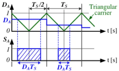
By convention, the gating pulses will be centered into the switching period TS, as illustrated on Fig. 2. Generally, there will be two switchings per switch over a switching period.
The mean values of the inverter output voltages over TS are given by the following expressions:
K
A
B
C
N
V
KG TE
DCD
K S
,
,
,
,
K
A
B
C
V
KN TE
DC
D
KD
N
S
,
,
,
and, by considering each leg of the inverter individually:
K
A
B
C
N
V
KG T
E
DC
S0
,
,
,
,
,
K
A
B
C
V
KN T
E
DCE
DC
S,
,
,
,
The mean value notation will be subsequently removed for voltage quantities, since mean values are used for computa-tions.
III. ANEW PWMMETHOD ALLOWING SMOOTH TRANSITION BETWEEN CONTINUOUS AND DISCONTINOUS PWM SCHEMES A. A control allocation method for the 4-leg 2-level inverter
using a per-switch functional formulation 1) Per-switch functional formulation
The 4-leg 2-level inverter control problem can be formulated by considering its mathematical function. Under the assump-tions mentioned above, for each switching period TS, the objec-tive is to find a set of duty cycles DK to obtain a reference vec-tor Vref of load voltages VKNref:
A B C EDC SA SB SC SA SB SC G
FOUR-LEGTWO-LEVELINVERTER
DC TOAC N SN SN ZA ZB ZC 3-PHASE LOAD N
Fig. 1. Illustration of the 4-leg 2-level inverter connected to a three-phase load with impedances ZA, ZB, ZC.
SA t [s] TS /2 0 1 DATS TS DA t[s] 0 1 DA Triangular carrier DATS
Fig. 2. Illustration of the realization of gating pulse on switch A of width
ABC
VKNref VKN T EDC
DK DN
K S , , , Define ΔDref, the scaled reference vector, as follows:
ref CN ref BN ref AN DC ref refD
D
D
E
V
D
ΔDref is similar to the difference of duty cycles between the three first legs and the fourth one.
From the expressions of the load voltages as functions of the switching states, one finds the matrix functional formulation:
N C B A refD
D
D
D
D
1
1
0
0
1
0
1
0
1
0
0
1
K
A,B,C,N
, 0DK1 Without constrains, the system would have an infinite number of solutions. The constraints (16) expressed on the duty cycles are an additional difficulty for solving the problem.
2) Control allocation methods
Control allocation methods are an interesting solution for han-dling degree of freedoms available for the control of the invert-er [10]. Control allocation theory was developed as a solution for overdetermined problems (that can have more than one solution) and whose decision variables are subjected to con-straints [9]. Flight control is a primary field of application [8].
Control allocation methodology rests on three points:
one wants to impose reference values to some quantities to be controlled;
one has resources that are generally redundant;
there are constraints mainly linked to resources, or ac-tuators’ ranges of motion, that have to be respected in order to obtain the desired quantities.
The main objective is to realize an automatic distribution of the references to the available resources while respecting the constraints, and to do this at each control instant. Most of the time, difficulties come from the constraints that reduce the set of solutions, although these solutions may not be unique, even with constraints.
For the 4-leg 2-level inverter, the references are the desired load voltages, the constraints are linked to the limited time of the switching period [10], and the switching cells are the re-sources.
For the problem (15)-(16), one searches a solution that is
feasible, i.e., respects the constraints on the duty cycles, and
results in the desired load voltages. There might be zero, one, or an infinity of such solutions. An interesting proposition is to find a solution for the problem in an optimized manner, by formulating one or more performance or control criteria. The on-line computation cost is high, but the performances of
mod-ern computers or digital signal processors increasingly allow one to overcome this issue.
B. OMIPWM : A particular configuration of a control allocation technique dedicated to the 4-leg 2-level inverter
The modulation method introduced in this paper comes from a specific choice of optimization criterion. More details about the general control allocation method will be given in a future pa-per. Here, the focus is placed on the original properties of the specific case. The result will be interpreted as a CBPWM method, with triangular intersection.
Fig. 3 shows the corresponding control diagram. Under the assumptions formulated in this paper, the duty cycles can be obtained by choosing DN while respecting the correct distances between the duty cycles expressed by ΔDref:
N ref C B A
D
D
D
D
D
The injection of the zero-sequence voltage can be represent-ed by the waveform of the fourth duty cycle DN through the quantity DZSV:
D
N
D
ZSV2
1
In the case of a three-phase balanced system, it corresponds to the well-known form of any modulating signal:
ZSV DC ref C B AD
t
t
t
E
A
D
D
D
3
/
2
sin
3
/
2
sin
sin
2
1
where Aref is the peak amplitude of the three-phase reference voltage system.
To ensure that all duty cycles are between 0 and 1, the fol-lowing bounds must be satisfied:
VANref VBNref VCNref 3 VOLTAGE REFERENCES 1 1/2 + - sat -+ 1/EDC 1 + + DANref DBNref DCNref 3 DA DB DC ZERO-SEQUENCE INJECTION THROUGH DN
DN + -0 1 0 TRIANGULAR CARRIER RELAY SA SB SC SN 4 MODULATOR VAN VBN VCN 3 Load IA IB IC sort + -0 + k SCALED REFERENCES 1 1 1 3 1 DUTY CYCLES 4 median min max FOUR-LEG TWO-LEVEL INVERTER EDC + -DNmin DNmax ΔDref -DZSV
Fig. 3. Proposed control diagram, based on the ordering of the reduced reference voltages. The parameter k quantifies the injection of the opposite of the median voltage as a zero-sequence.
D
Nmin
min
D
ref
D
Nmax
1
max
D
ref
max
min N N
N
D
D
D
The quantities DNmin and DNmax specify the available margin for injecting zero-signals while ensuring feasible duty cycles. To be rigorous, these bounds should be further limited to the inter-val from 0 to 1, but this step is omitted for simplicity. If DN stays between DNmin and DNmax, the desired load voltages can be achieved.
The higher the reference amplitude is, the smaller the do-main described by these two bounds becomes. In the case of a three-phase balanced system, the linearity range is extended to 1/3·EDC, i.e., almost 58% of the DC bus voltage. When DN =
DNmin, one leg will be clamped to the negative pole of the DC bus (ground) and, for a whole fundamental period, this choice corresponds to a modulation of type DPWMmin. When DN =
DNmax, one leg will be clamped to the positive pole of the DC bus and, for a whole fundamental period, this choice corre-sponds to a modulation of type DPWMmax.
The particularity of OMIPWM lies in the combined effects of the saturation of DN by DNmin and DNmax and by the use of the opposite of the median reference voltage as a zero-sequence. Actually, the median reference voltage is an advantageous and quite simple choice of zero-sequence voltage, as it is complete-ly composed of harmonics that are multiple of three and is di-rectly deduced from the three reference voltages. It has been shown that the regular-sampled symmetric PWM with injection of the half of the median reference voltage is equivalent to SVM [11]. This result can be also deduced from other studies [12]–[13]. In [14], the given formulas for SVM can be ex-pressed with our notation as follows:
2
min
max
2
1
2
max min ref ref N N SVM ND
D
D
D
D
Under the “three-phase reference voltages” assumption, the sum of the reference voltage is null, and the SVM correspond-ing zero-sequence signal is
ref SVM ZSV
D
D
med
2
1
A crucial point is the fact that (23) means that DN SVM is the mean (or the center) of DNmin and DNmax. Thus, discontinuous modulation is naturally avoided when using (23) and when
DNmin is inferior to DNmax.
Contrary to this property, the new zero-sequence signal pro-posed by OMIPWM is still based on the median voltage, but through the choice:
ref
OMIPW M
ZSV
D
D
med
As the reference amplitude increases, DN will be more inclined to reach the bounds DNmin and DNmax and, at that moment,
dis-continuous modulation appears with increasing disdis-continuous periods. OMIPWM is a simple method that automatically en-sures the transition from a continuous to a discontinuous modu-lation scheme as a function of the reference amplitude. When in discontinuous modulation mode, all switches will be once clamped to the DC bus and once to the ground over a funda-mental period, as it will be shown in the next section.
An improvement of the method can be obtained by the in-troduction of an injection factor k,
ref
OMIPW M
ZSV
k
D
D
med
that modulates the transition effect and causes a transition from continuous to discontinuous modulation at an adjustable level. This will be also illustrated later.
The determination of DNmin, DNmax and the zero-sequence signal DZSV, is obtained from an ordering of the three reference voltages, needing 2 comparisons. Then, the duty cycles are determined by adding the chosen DN to the scaled reference vector ΔDref. Finally, the gating signals are given by the modu-lator block.
IV. SIMULATION RESULTS
In this section, OMIPWM is evaluated in simulation and com-pared with SVM, DPWMmin and DPWMmax through differ-ent criteria. Simulations were carried out in a MATLAB-Simulink environment. The main simulation parameters are summarized in Table I. All simulations were performed under the “three-phase balanced voltages and load” assumption for simplicity. Therefore, the same results can be obtained with the three-leg inverter.
Duty cycle waveforms are shown on Fig. 4. The reference amplitude value increases from left (a) to right (c) until the limit of 1/3 is reached. The representation of duty cycles as functions of the variable =2ft, t being time, allows
abstrac-tion of the fundamental frequency f. A whole fundamental pe-riod is illustrated. OMIPWM is configured with k = 1.
The zero-sequence signals can be deduced from DN wave-forms on the upper curves (x1) of Fig. 4. On these figures, the extremal bold curves correspond to the bounds specified by
DNmin and DNmax. The respect of these limits ensures that the resulting duty cycles DA, DB, DC are between 0 and 1. On Fig. 4 (a1), the bounds are not reached and DN OMIPWM corresponds to the opposite of the median reference voltage. Contrary to SVM, where the zero-sequence voltage is the half of the posi-tive median voltage, for OMIPWM, the distance between
DN OMIPWM and the bounds DNmin and DNmax at the points =/6 +
n*/3, n=0..5, is small and decreases when the reference ampli-tude increases. This is the reason why saturation appears on
TABLE I. SIMULATION PARAMETERS
Symbol Meaning Values
EDC DC bus voltage 400 V
fs Switching frequency 10 kHz
f Load current frequency 50 Hz
R Load resistance 0.5 Ω
0 pi/2 pi 3*pi/2 2*pi 0.1 0.2 0.3 0.4 0.5 0.6 0.7 0.8 0.9 [rad] S a tu ra te d D N DNmax DNmin DN OMIPWM (a1)
0 pi/2 pi 3*pi/2 2*pi
0.2 0.3 0.4 0.5 0.6 0.7 0.8 [rad] S at ur at ed D N DNmax DNmin nonsaturated DNOMIPWM DNOMIPWM (b1)
0 pi/2 pi 3*pi/2 2*pi
0.2 0.3 0.4 0.5 0.6 0.7 0.8 [rad] S at ur at ed D N DNmax DNmin nonsat DNOMIPWM DNOMIPWM (c1)
0 pi/2 pi 3*pi/2 2*pi
-0.2 0 0.2 0.4 0.6 0.8 1 1.2 [rad] DA ( sa tu ra te d D N ) fundamental DAOMIPWM (a2)
0 pi/2 pi 3*pi/2 2*pi
-0.2 0 0.2 0.4 0.6 0.8 1 1.2 [rad] DA ( sa tu ra te d D N ) fundamental DAOMIPWM DAOMIPWM if DNOMIPWM nonsat out of frame
out of frame
(b2)
0 pi/2 pi 3*pi/2 2*pi
-0.2 0 0.2 0.4 0.6 0.8 1 1.2 [rad] DA ( sa tu ra te d D N ) fundamental DAOMIPWM
DAOMIPWM if DNOMIPWM nonsat out of frame
out of frame
(c2)
Fig. 4. Waveforms of DN (1, up) and DA (2, down) from OMIPWM for several reference amplitudes. (a) Vref = 0.3EDC. (b) Vref = 0.5EDC. (c) Vref = 1/3EDC.
0.1 0.15 0.2 0.25 0.3 0.35 0.4 0.45 0.5 0.55 0 20 40 60 80 100 120
Normalized reference amplitude [% of EDC]
DA s a tu ra te d s u b c y c le [ d e g re e s ] SVM DPWMmin,max OMIPWM k=.1 k=.5 k=1 k=2 k=3 k=5 k=8 k=12 k=20 SVM DPWMmin,max k=0 k=40 OMIPWM
Fig. 5. Total clamping duration (in degrees) per switch over a fundamental period as a function of the reference amplitude.
0.1 0.15 0.2 0.25 0.3 0.35 0.4 0.45 0.5 0.55 0.6 34 36 38 40 42 44 46 48 50 52 54 Switching losses
Normalized reference amplitude [% of E
DC] S w it c h in g l o s s e s [ J ] DPWMmax DPWMmin OMISPWM SVM OMI PWM OMIPWM
Fig. 6. Total switching losses of the inverter as functions of the reference amplitude (k=1). 0.1 0.15 0.2 0.25 0.3 0.35 0.4 0.45 0.5 0.55 0.6 0.4 0.45 0.5 0.55 0.6 0.65 0.7 0.75 0.8 0.85 0.9 THD on IA
Normalized reference amplitude [% of EDC]
T H D [ % ] DPWMmax DPWMmin OMISPWM SVM OMI PWM OMIPWM
Fig. 7. Total harmonic distortion on phase A load current as a function of the reference amplitude (k=1). 0.1 0.15 0.2 0.25 0.3 0.35 0.4 0.45 0.5 0.55 0.6 100 150 200 250 300 350 THD on VAN
Normalized reference amplitude [% of EDC]
T H D [ % ] DPWMmax DPWMmin OMISPWM SVM OMIPWM
Fig. 8. Total harmonic distortion on phase A load voltage as a function of the reference amplitude (k=1).
Fig. 4 (b1). The typical quasi-triangular waveform of the un-saturated DN OMIPWM is seen as the dash-dotted blue curve, which crosses the bounds and causes the appearance of discon-tinuous modulation scheme. Over the fundamental period, the parts of DN OMIPWM saturated by DNmin and DNmax correspond to periods where a leg is continuously clamped to the DC bus or to the ground, as observed on the waveform of DA on Fig. 4 (b2). As a result of this saturation, the waveform of DA OMIPWM is modified, compared to Fig. 4 (a2), in order to obtain the cor-rect fundamental waveform (black dashed line).
At the maximum voltage of 1/3·EDC permitting linearity, OMIPWM is equivalent to DPWM1 scheme [1], [7], [15], re-sulting in an alternation of 60°-width periods between DPWMmin and DPWMmax.
Fig. 5 illustrates clearly the smooth transitional effect of OMIPWM. For DPWM schemes, the total clamping period over a fundamental period corresponds to 120° (per switch). For OMIPWM, from a certain amplitude value, this period becomes non null and increases until the maximum value of 120° at the maximum reduced reference amplitude of 1/3. The injection coefficient k makes the transition more or less abrupt. This result is obtained through a transition that starts earlier and ends later.
The transition effect also has an effect on the switching losses, shown on Fig. 6. As the evaluation of switching losses depends on the load characteristics and the modulation method, we focus our attention only on the general trends of the curves. Two quasi-parallel lines, one higher than the other, describe the evolution of the switching losses, respectively, for SVM and for DPWMmin, DPWMmax. The trend for OMIPWM is re-markable since the curve falls from the SVM curve to the DPWM curves as a function of the amplitude.
Fig. 7 and Fig. 8 show the evolution of the total harmonic distortion (THD) on currents and on voltages, respectively. THD was evaluated thanks to the thd function of the Signal Processing Toolbox available in the MATLAB environment. Fig. 8 shows that THD trends on voltages are very close for all methods, but differences appear for THD’s on currents, see Fig. 7, meaning differences on the spectral distribution. OMIPWM current THD trend is singular again. At low ampli-tude, THD on the currents is higher than SVM but fairly close compared to DPWM ones. As the amplitude increases, THD on currents for OMIPWM converges to DPWM THD’s, which have decreased and are closer to the SVM’s THD.
In conclusion, OMIPWM gives better harmonic perfor-mance at low voltage amplitude and lower switching losses at high voltage amplitude, meaning an advantageous compromise between continuous and discontinuous modulation properties as a function of the reference voltage amplitude. Thus, it might be interesting to consider this method for supplying a three-phase machine. At low speeds (low voltages, low modulation depths), one has an interest in favoring THD in order to limit torque ripple. For high speeds, ripple is better filtered and it is more interesting to reduce switching losses.
V. CONCLUSION
A new carrier-based PWM technique for a voltage source in-verter is presented in this paper. It uses the opposite of the
me-dian reference voltage as a zero-sequence voltage, which yield-ed the acronym OMIPWM. The PWM method has the same linear range as the SVM, while offering a new, automatic tran-sition between continuous and discontinuous modulation schemes. The period of transition from the continuous to dis-continuous can be adjusted by setting a single parameter. The method was obtained using a specific configuration of a control allocation method for the 4-leg 2-level inverter that will be discussed in a future paper.
Results were obtained in simulations and various wave-forms were shown. OMIPWM gives a new compromise be-tween the good harmonic performance of continuous PWM methods like SVM and the reduced switching losses of discon-tinuous PWM methods like DPWMmin and DPWMmax.
REFERENCES
[1] D. G. Holmes and T. A. Lipo, Pulse Width Modulation for Power
Converters: princples and practice, New York:
IEEE/Wiley-Interscience, 2003.
[2] J. Holtz, “Pulsewidth Modulation for Electronic Power Conversion,”
Proc. IEEE, vol. 82, no. 8, pp. 1194–1214, Aug. 1994.
[3] H. W. Van der Broeck, H.-C. Skudelny and G. V. Stanke, “Analysis and Realization of a Pulsewidth Modulator Based on Voltage Space Vectors,” IEEE Trans. on Industry Applications, vol. 24, no. 1, pp. 142– 150, Jan.–Feb. 1988.
[4] S. R. Bowes, “New sinusoidal pulsewidth-modulated invertor,” Proc.
Inst. Elect. Eng., vol. 122, pp. 1279–1285, Nov. 1975.
[5] G. Buja and G. Indri, “Improvement of Pulse Width Modulation Techniques,” Archiv für Elektrotechnik, vol. 57, pp. 281–289, 1975. [6] J. A. Houldsworth and D. A. Grant, “The Use of Harmonic Distortion to
Increase the Output Voltage of a Three-Phase PWM Inverter,” IEEE
Trans. on Industrial Applications, vol. IA–20, no. 5, pp. 1224–1228,
Sept.–Oct. 1984.
[7] A. M. Hava, R. J. Kerkman and T. A. Lipo, “A High-Performance Generalized Discontinuous PWM Algorithm,” IEEE Trans. on Indus.
Appl., vol. 34, no. 5, pp.1059–1071, Sept.–Oct. 1998.
[8] M. Bodson, “Evaluation of Optimization Methods for Control Allocation,” Journal of Guidance, Control and Dynamics, vol. 25, no. 4, pp. 703–711, July–Aug. 2002.
[9] T. A. Johansen and T. I. Fossen, “Control Allocation–A survey,”
Automatica, vol. 49, pp. 1087–1103, 2013.
[10] A. Bouarfa, M. Fadel, M. Bodson and J. Lin, “A New Control Allocation Method for Power Converters and its Application to the Four-Leg Two-Level Inverter,” in IEEE 23rd Mediterranean Conf.
Control and Automation (MED 2015), Torremolinos, Spain, pp. 1020–
1026, June 2015.
[11] P. F. Seixas, “Commande numérique d’une machine synchrone autopilotée,” Ph.D. thesis, INPT, Toulouse, France, 1988.
[12] D. W. Chung, J. S. Kim and S. K. Sul, “Unified voltage modulation technique for real time three-phase power conversion,” in Proc. Conf.
Rec. IAS, pp. 921–926, 1996.
[13] C. B. Jacobina, A. M. N. Lima, E. R. C. da Silva, R. N. C. Alves and P. F. Seixas, “Digital Scalar Pulse-Width Modulation: A Simple Approach to Introduce Non-Sinusoidal Modulating Waveforms,” IEEE Trans.
Power Electronics, vol. 16, no. 3, pp. 351–359, May 2001.
[14] X. Li, Z. Deng, Z. Chen and Q. Fei, “Analysis and Simplification of Three-Dimensional Space Vector PWM for Three-Phase Four-Leg Inverters,” IEEE Trans. Industrial Electronics, vol. 58, no. 2, pp. 450– 464, Feb. 2011.
[15] M. Depenbrock, “Pulse width control of a 3-phase inverter with nonsinusoidal phase voltage,” in Conf. Rec. IEEE Int. Semiconductor