HAL Id: hal-00538605
https://hal.archives-ouvertes.fr/hal-00538605
Submitted on 22 Nov 2010HAL is a multi-disciplinary open access archive for the deposit and dissemination of sci-entific research documents, whether they are pub-lished or not. The documents may come from teaching and research institutions in France or abroad, or from public or private research centers.
L’archive ouverte pluridisciplinaire HAL, est destinée au dépôt et à la diffusion de documents scientifiques de niveau recherche, publiés ou non, émanant des établissements d’enseignement et de recherche français ou étrangers, des laboratoires publics ou privés.
Design and FPGA prototyping of a bit-interleaved
coded modulation receiver for the DVB-T2 standard
Meng Li, Charbel Abdel Nour, Christophe Jego, Catherine Douillard
To cite this version:
Meng Li, Charbel Abdel Nour, Christophe Jego, Catherine Douillard. Design and FPGA proto-typing of a bit-interleaved coded modulation receiver for the DVB-T2 standard. Signal Processing Systems (SIPS), 2010 IEEE Workshop on, Oct 2010, San Francisco, United States. pp.162 -167, �10.1109/SIPS.2010.5624781�. �hal-00538605�
DESIGN AND FPGA PROTOTYPING OF A BIT-INTERLEAVED CODED MODULATION
RECEIVER FOR THE DVB-T2 STANDARD
Meng Li, Charbel Abdel Nour, Christophe Jégo and Catherine Douillard
Institut Telecom, Telecom Bretagne, CNRS Lab-STICC UMR 3192Electronic Engineering Department, Technopôle Brest Iroise, CS 83818 29238 Brest Cedex 3 Université Européenne de Bretagne, France
ABSTRACT
Signal Space Diversity (SSD) has been lately adopted into the second generation of the terrestrial digital video broadcasting standard DVB-T2. In this paper, a bit-interleaved coded modulation receiver for the DVB-T2 standard is detailed. An LDPC decoder based on a vertical layered schedule is the main novelty of this work. It enables an efficient exchange of extrinsic information between the rotated demapper and the LDPC decoder if an iterative receiver is considered. The design and the FPGA prototyping of the resultant architecture are then described. Low architecture complexity and good performance represent the main features of the proposed receiver.
1. INTRODUCTION
It has been shown by Zehavi [1] that the performance of coded modulation can be improved over a Rayleigh fading channel by bit-wise interleaving at the Forward Error Correcting (FEC) encoder output, and by using an appropriate soft-decision metric at the FEC decoder input. This principle, called Bit-Interleaved Coded Modulation (BICM), currently represents the reference in coded modulations over fading channels. The SSD principle introduced in [2-3] improves the diversity order of BICM schemes over fading channels. It is divided into two steps. The first step consists of rotating the constellation in signal space following a particular angle value. The second step applies an interleaving of one of the In-phase (I) or Quadrature (Q) components of the signal with respect to the other. When concatenated with FEC codes, modulations with SSD show an improvement in performance for high coding rates [4] over fading channels. In the presence of erasure events, BICM with SSD achieves higher spectral efficiencies beyond the redundancy ratio of the outer FEC [4]. In addition, improvement in performance by several dBs over severe channel conditions has been observed.
The BICM with Iterative Demodulation or Demapping (BICM-ID) proposed in [5] is based on an iterative receiver with additional soft feedback from the Input Soft-Output (SISO) decoder to the constellation demapper. In [6], the convolutional code classically used in BICM-ID schemes was replaced by a turbo code. BICM-ID with an
LDPC code was studied for different DVB-T2 transmission scenarios in [4]. The authors show that an iterative demapping associated with SSD provides additional error correction that can exceed 1.0 dB over some channel types. Thanks to theses advantages, BICM-ID has been pointed out in the implementation guidelines of the DVB-T2 standard [7] as one of the important means for improving performance at the receiver side. Best DVB-T2 error rate performance results are obtained when iterative demodulation is applied.
However, the application of BICM-ID with SSD has an important impact on the design of the rotated QAM demapper and the LDPC decoder. When Gray mapping is used, applying a rotation to the signal constellation breaks the independence between the in-phase and quadrature components of the QAM. Consequently, the Maximum Likelihood (ML) QAM detector cannot apply two independent Pulse Amplitude Modulation (PAM) detectors anymore. Instead, both I and Q signal components are needed for the computation of the demapper metrics. The design of high throughput, low complexity, low latency architectures for a BICM with SSD becomes a challenge. In [8], flexible mapper and demapper architectures for DVB-T2 are presented. The decomposition of the constellation into two-dimensional sub-regions in signal space associated with additional algorithmic simplifications represents the main novelty of [8]. They enable to strongly decrease the complexity of the demapper.
LDPC codes can be efficiently decoded using the Belief Propagation (BP) algorithm. This algorithm operates on the bipartite graph representation of the code by iteratively exchanging messages between the variable and check nodes along the edges of the graph. The Min-Sum (MS) algorithm, which is an alternative method, can significantly reduce the hardware complexity of the BP algorithm. Moreover, modified versions of MS algorithm such as normalized MS or offset MS using additional correction factors offer comparable decoding performance over the BP algorithm. Based on these different improvements, many LDPC decoders have been described in previous papers; a brief review can be found in [9]. The schedule defines the order of passing messages between all the nodes of the bipartite
graph. Since a bipartite graph contains some cycles, the schedule directly affects the algorithm’s convergence rate and hence its computational complexity. The classical schedule is flooding where decoder iteration is divided into two phases: in the first phase, all the variable nodes send messages to their neighbouring check-nodes, and in the next phase the check-nodes send messages to their neighbouring variable nodes. More efficient layered schedules have been proposed in literature [10]. Indeed, the parity check matrix can be viewed as a horizontal or a vertical layered decoded sequentially. Decoder iteration is then split into sub-layer iterations. The layered schedules enable the decoding convergence to speed up. They can also ensure a good matching between decoding algorithms on one hand and decoder architectures on the other hand.
For a BICM-ID scheme, an efficient exchange of extrinsic information between the demapper and the decoder has to be applied. Indeed, the ID imposes a latency that can have an important impact on the whole receiver. Shuffled versions of the standard iterative decoding algorithms for both LDPC and turbo codes are presented in [11]. The proposed schemes have about the same computational complexity as the standard versions while enjoying faster iterative process convergence. This principle can be extended to BICM-ID in order to design a low-latency receiver. It forces however a vertical layered schedule for the decoding of the LDPC codes. Vertical layered schedule for the BP algorithm is found in literature. To our knowledge, normalized MS based on vertical layered decoding was only studied in [12]. Moreover, the problem of memory access conflicts for layered architectures has never been addressed in the case of a normalized MS based on vertical layered decoding. As a possible solution, we extend the reordering mechanism of the DVB-T2 parity check matrix detailed in [13], to a vertical layered schedule. We also solved the message updating inefficiency caused by the double diagonal sub-matrices during the decoder design. The remainder of the paper is organized as follows. Section 2 recalls the basic principles of the BICM-ID and SSD. Section 3 details a vertical layered decoding using a normalized MS algorithm. The challenging issue of resolving memory conflicts is developed in Section 4. Finally, an implementation of the proposed LDPC decoder for a BICM receiver and its experimental setup onto an FPGA device are presented.
2. BICM-ID SYSTEM
The channel model used to simulate and emulate the effect of erasure events is a modified version of the classical Rayleigh fading channel. More information about this model is given in [8].
2.1. BICM-ID with SSD
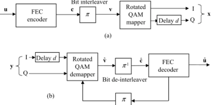
The SSD principle consists of introducing modifications to the mapper and demapper as shown in Fig. 1. The QAM constellation is rotated by an angle α and the component
axes are interleaved [5]. The in-phase and quadrature components are therefore subject to two different fading coefficients increasing the degree of diversity of the BICM scheme. Bit interleaver FEC encoder Rotated QAM mapper c u v x Delay d I Q π Bit de-interleaver Rotated QAM demapper FEC decoder y Delay d I Q vˆ cˆ uˆ π-1 (a) (b) π (b)
Fig. 1: the BICM-ID with SSD structure (a) transmitter and (b) receiver
The information frame u goes through the FEC encoder to generate the codeword c . Afterwards, this sequence c is interleaved using the bit interleaver π to generate the mapper input sequence v. At time t, m consecutive bits of the interleaved sequence v are mapped to complex symbol
t
x . At the receiver side, the Log Likelihood Ratio (LLR) computation has to take into account the introduced modifications (cf. Fig. 1(b)). For Gray-mapped QAM constellations, the demapper calculates a two-dimensional squared Euclidean distance for the computation of the LLR
ˆi t
v related to the ith bit of vt. After de-interleaving, the LLRs
are used as inputs to the decoder. When the received signal
t
y is erased, the LLR computation is updated accordingly. The extrinsic exchange of soft information is initiated between the decoder and the demapper thanks to a soft feedback.
2.2. The LDPC code of the DVB-T2 standard
Irregular Repeat Accumulate (IRA) codes are a family of special LDPC codes which can be encoded/decoded with linearcomplexitywhilestillkeepinggoodBERperformance. An IRA code is characterized by a parity check matrix composed of two sub-matrices: a sparse sub-matrix and a staircase lower triangular sub-matrix. Moreover, periodicity has been introduced in matrix design in order to reduce storage requirements. This family of LDPC codes has been adopted in the DVB-T2 standard. Unfortunately, the parity check matrices are not perfectly structured for layered decoding architectures, leading to some memory access conflicts. Moreover, an important issue in the design of LDPC decoder architectures for DVB-T2 is the fact that the standard supports multiple frame and code rate scenarios. Actually, two different frame lengths (16200 bits and 64800 bits) and a set of different code rates (1/2, 3/5, 2/3, 3/4, 4/5 and 5/6) have been adopted. In this paper, we propose a novel LDPC decoder architecture particularly suited to the BICM-ID context in order to closely approach best performance results provided in the implementation guidelines of the DVB-T2 standard.
3. A VERTICAL LAYERED DECODING SCHEME USING A NORMALIZED MS ALGORITHM 3.1 Vertical layered schedule
By means of the Gauss-Seidel algorithm, a vertical layered schedule for the BP algorithm updates the messages between check and bit nodes in a column by column way. In the sake of clarity, the algorithm is described as a fully serialized version, in which the messages are processed one by one. Let llrn denote the intrinsic channel reliability value of the variable node n , Emndenotes the message sent from check node m to bit node n , Tmndenote the message sent from variable node n to check node m and Tn denote a
posteriori log-likelihood ratio of bit node n during each
iteration.
Vertical layered BP algorithm 0. Initialization: 1. Tmn(0)=llrn m M n∈ ( ) 2. (0) ( ) sgn( ) m n m M n llr α ∈ =
∏
, (0) ( ) ( ) m n m M n llr β ϕ ∈ =∑
3. Iterative decoding 4. ∀ =t 1, 2,...,tmax // iteration 5. ∀ =n 1, 2,...,N // sub-iteration // check node processing6. ( )t sgn( ( 1)t ) ( ( ( 1)t ))
mn m mn m mn
E =α ⋅ T − ⋅ϕ β −ϕ T −
// bit node processing
7. ( ) ( ) ( ) t t n n mn m M n T llr E ∈ = +
∑
Tmn( )t =Tn( )t −Emn( )t// check node update for next sub-iteration 8. sgn( ( 1)t ) sgn( ( )t ) m m Tmn Tmn α =α ⋅ − ⋅ m M n∈ ( ) 9. ( ( 1)t ) ( ( )t ) m m Tmn Tmn β =β −ϕ − +ϕ m M n∈ ( )
10. Hard decision according to sign( ( )t n
T )
The decoding algorithm consists of passing messages mn
T from variable nodes to parity check nodes and messages mn
E from parity check nodes to variable nodes during an iterative process. In the serial vertical layered algorithm, one iteration is split into n sub-iterations, one for every layer.
First, the messages Tmn and values α and m β are m initialized with the intrinsic channel reliabilities llrn. Each sub-iteration is composed of three steps: check node processing, bit node processing and α , m β value update. m The check node processing is based on the property of
1( )x ( ) (x x 0)
ϕ− =ϕ > , with ( ) log tanh( ) 2
x x
ϕ ≡ − . Then,
the a posteriori log-likelihood ratio ( )t
n
T for bit node n is
achieved by adding all the ( )t mn
E to llrn. The messages ( )t mn
T
are computed from ( )t n
T . The α , m β values are updated m
according to the messages ( )t mn
T . Finally, the hard decision is
taken from the sign of ( )t n
T .
One of the main advantages of the vertical layered schedule is faster decoding convergence. By comparison with a flooding schedule, less iterations are needed thanks to
the computation of variables α and m β . m
' ' ' ' ( ) ( 1) ( )\ ( )\ ( t ) ( t ) m mn mn n N m n n N m n n n n n T T β ϕ ϕ − ∈ ∈ < > =
∑
+∑
' ' ' ' ( ) ( 1) ( )\ ( )\ sgn( t ) sgn( t ) m mn mn n N m n n N m n n n n n T T α − ∈ ∈ < > =∏
⋅∏
The vertical layered schedule is particularly suited for a hardware design in the sense that it can reduce the required number of memory accesses. Tmn is used and updated only once by iteration and the α and m β are used and updated m
dctimes by iteration.
3.2 Normalized MS algorithm
A normalized MS vertical layered message passing algorithm has been studied to reduce hardware complexity. Following the principle of MS algorithm for horizontal layered decoding, the vertical layered MS uses λ (λ≥2) minimum values of Tmn to simplify the check node processing.
Vertical layered normalized Min-Sum algorithm 0. Initialization: 1. ∀ =n 1, 2,...,N 2. sgn(Tmn) sgn(= llrn) m M n∈ ( ) 3. ( ) sgn( ) m n m M n llr α ∈ =
∏
4. Mm0 =min(llrn) 1 secmin( ) m n M = llr 5. 0 ( 0) m m P =nindex M 1 ( 1) m m P =nindex M 6. Iterative decoding 7. ∀ =t 1, 2,...,tmax // iteration 8. ∀ =n 1, 2,...,N // sub-iteration // check node processing 9. if (n== 0 m P ) ( )t sgn( ( 1)t ) 1 mn m mn m E =α η⋅ ⋅ T − ⋅M else ( )t sgn( ( 1)t ) 0 mn m mn m E =α η⋅ ⋅ T − ⋅M// bit node processing
10. ( ) ( ) ( ) t t n n mn m M n T llr E ∈ = +
∑
( )t ( )t ( )t mn n mn T =T −E// check node update for next sub-iteration 11. sgn( ( 1)t ) sgn( ( )t ) m m Tmn Tmn α =α ⋅ − ⋅ m M n∈ ( ) 12. ' 0 min( ( )t , ( 1)t ) m mn mk M = T T − ( ) \k'∈N m n 13. ' 1 secmin( ( )t , ( 1)t ) m mn mk M = T T − 14. Pm0 =nindex M( m0) Pm1 =nindex M( 1m) 15. Hard decision according to sign( ( )t
n
0
m
M and 1
m
M are the minimum and second minimum values
of Tmn for check node m . 0
m
P and 1
m
P are the corresponding bit node index of 0
m
M and 1
m
M , that belong to the set of n N m∈ ( ).Letη denotethescalingfactorfor thecorrection of the over-estimation introduced by the MS algorithm. Thus, the most complex part of normalized MS vertical layered message passing algorithm is the update of
0 m M , 1 m M and 0 m P , 1 m
P . Note that this part is quite different
from the horizontal layered schedule. Let’s take the update of 0
m
M at the nth sub-iteration as an example. Three cases have to be considered.
1-) 0
m
P = n , 0
m
M is selected from the previous 1
m M and ( )t mn T , 2-) 1 m P =n , 0 m
M is selected from the previous 0
m M and ( )t mn T , 3-) 0 m P ≠n and 1 m P ≠n , 0 m
M is selected from the previous
0 m M , previous 1 m M and ( )t mn T .
Normally, the update of 1
m
M needs a third minimum value as a candidate of the second minimum (λ=3). However, simulation results showed that only 0.05dB performance penalty is observed if λ=2. Consequently, this value has
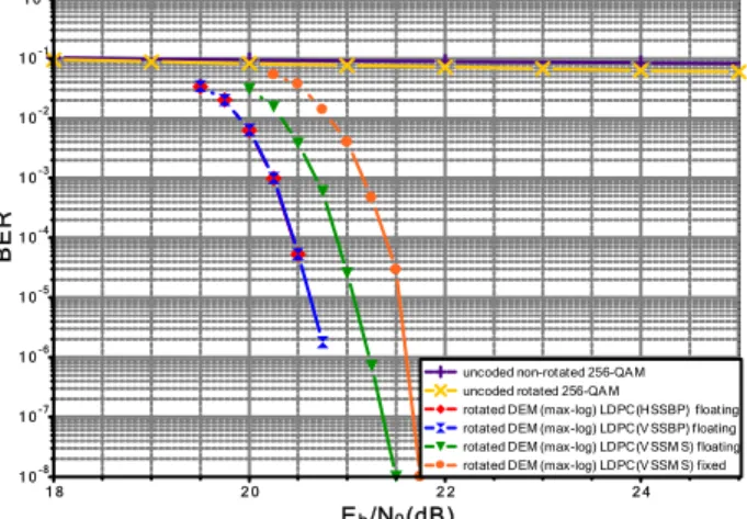
been chosen in our study. The impact of the normalized vertical layered MS algorithm for the decoding of DVB-T2 LDPC codes is illustrated in Fig. 2. Simulations were carried out for four decoding algorithms with a maximum number of 50 iterations: horizontal and vertical layered BP, floating-point and fixed-point versions of vertical layered normalized MS. For comparison, the uncoded 256-QAM is also plotted. Simulation results show that no significant BER deviation is observed between horizontal and vertical layered BP algorithms. BP algorithm outperforms normalized MS algorithm by about 0.4 dB at 10-6. An
additional penalty of 0.3 dB is introduced for a fixed-point version of the normalized MS algorithm. Results show decoding performance close to floating-point BP algorithm.
1 8 2 0 2 2 2 4 Eb/N0(dB) 1 0-3 1 0-2 1 0-1 1 00 1 0-4 1 0-5 1 0-6 1 0-7 1 0-8 B E R
uncoded non-rotated 256-QAM uncoded rotated 256-QA M
rotated DEM (max-log) LDPC(HSSBP) floating rotated DEM (max-log) LDPC(V SSBP) floating rotated DEM (max-log) LDPC(V SSM S) floating rotated DEM (max-log) LDPC(V SSM S) fixed
Fig. 2: BER at the outputs of the demapper and LDPC decoder for BP and normalized MS algorithms. Code rate R = 3/4, rotated 256-QAM constellation, and 64,800-bit frames. Transmission over flat fading Rayleigh channel with 15% of erasure events.
4. DESIGN OF AN LDPC DECODER FOR BICM
The DVB-T2 LDPC codes are architecture-aware codes. It means that a pipeline decoder can be implemented in parallel to improve the throughput. But, similarly to the horizontal layered decoder, the memory access conflict problem is the bottleneck of the design of a high throughput, low complexity vertical layered MS LDPC decoder. To our knowledge, this is the first architecture design that overcomes memory access conflicts without additional delays in the decoding process when a normalized MS vertical layered message passing algorithm is considered.
4.1 Architecture of a vertical layered MS LDPC decoder
Fig. 3 details the architecture of the proposed vertical layered MS LDPC decoder for the DVB-T2 standard. It consists of two main blocks: bit node processor SISO-A and check node processor SISO-B. Since the DVB-T2 standard supports two long frames, 90 SISO-A and 90 SISO-B blocks have been designed to work in parallel in our architecture. For one sub-iteration, the 0
m M , 1 m M , 0 m P ,α m
and sgn(Tmn) values are read out from memories to compute
the extrinsic messages ( )t mn
E in SISO-B processor. Afterward, the messages ( )t
mn
E are sent thanks to a barrel shifter to different SISO-A processors. They are in charge of performing the sum of extrinsic messages in order to compute the a posteriori log-likelihood ratios ( )t
n
T and the messages ( )t
mn
T . These latter are then sent to the different SISO-B processors by using another barrel shifter for updating sgn(Tmn) , 0 m M , 1 m M , 0 m P , 1 m P and α values. m
Unlike a horizontal layered decoder, it is not possible to assign only one barrel shifter in the vertical layered decoder. Indeed, the information exchange between SISO-A and SISO-B processors has to deal with two different cases: LLR initialization and classical exchange.
( )t mn E n T ( )t mn T ( )t n T 0 1 0 M 1 M 0 index=P α
α
(( 1)) sgnTt− ( )( ) sgn t mn E ( )t mn E ( )( ) sgnTt ( )t T (( 1)) sgnTt− 0, 1 M M 0,1 P P ( ) sgnTmn 0 1 0 1 index M M P P index ( )t T (t1) α − 0 1 0 1 update M M P Pα 0 1 0 1 0 1Fig. 3: Architecture of the vertical layered MS LDPC decoder
4.2 Memory access conflict resolution
A pipeline process is generally applied in order to increase the throughput. The main bottleneck is the memory access conflicts for the check node memory bank in the case
of a vertical layered MS LDPC decoder. Fig. 4 shows the scheduling of one sub-iteration for three column layers with a bit node degree of three, where MP means the check node memory bank. In this case, six periods are necessary for updating the check node memory bank.
0,0 MP MP1,0 MP2,0 MP0,1 MP1,1 MP2,1 MP0,2 MP0,3 MP1,3 0,0 E E1,0 E2,0 E0,1 E1,1 E2,1 E0,2 E1,2 0,0 T T1,0 T2,0 T0,1 0,0 MP MP1,0 MP2,0 (old) SISOB ij E ij T (new) SISOB
= 3+3=6
delay dv
=
+
ε
1 T 0 T i Tcolumn layer 0 column layer 1 column layer 2
Fig. 4: Scheduling of the vertical layered MS LDPC decoder
Let i j
cad denote the address of the ith check node connected to the column j. If address 0
0
cad is read out more than once before the update of MP0,0, then there is a memory access conflict. The condition that leads to a conflict-free memory access is:
{ } {
i ( ) clk delay of i}
j j
cad ∩ dv+ε cad = ∅
To respect this constraint, we propose a design process without additional idle time. The first step is applied to the set of
{ }
ij
cad for each column j. Permutations are done
between the addresses of all the check node processors connected to one bit node processor. After splitting the sub-matrix like in [13], this first step of the construction process enables to overcome 90 percent of the memory access conflicts. For the unsolved cases, a second step is applied to the set of
{
{ } { } {
0i , 1i , , i 1}
}
n
cad cad ⋅⋅⋅ cad− for all the columns. Permutations done during this second step introduce some additional hardware control to manage the input/output accesses of bit node processors. However, the corresponding hardware cost is very low thanks to the reduced number of required permutations.
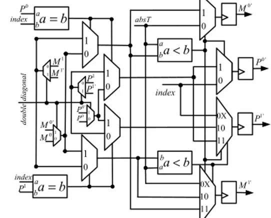
4.3 Conflicts due the parity check matrix structure
Parity check matrices for DVB-T2 LDPC codes are structured with shifted identify sub-matrices. Unfortunately, some sub-matrices contain two diagonals. It means that groups of variable nodes are connected twice to groups of check nodes. So, Double Diagonal Sub-Matrices (DDSM) introduce some memory access and update conflicts that have to be resolved during the decoder design. For example, if the column layer 0 of Fig. 4 has a DDSM, then two addresses 0
0
cad and 1 0
cad have to be processed at the same time. In this case, it is very difficult to avoid the conflict by a reordering mechanism, so the read data MP1,0is not the
latest updated value. Splitting the sub-matrix is a good way to reduce the number of DDSM. We propose a solution
based on this idea: for every DDSM conflict, only one memory position is allocated in the check node memory bank. However, two extrinsic messages Tmna and Tmnb get to be processed. Actually in our design, we first update the values { a m α , 0 a m M , 1a m M , 0a m P , 1a m
P } from Tmna. Then, these
values are saved in local registers as shown in Fig. 5. In a second time, these values and Tmnb are used to get the final values { b m α , 0 b m M , 1b m M , 0b m P , 1b m
P }. They are finally written in the check node memory bank. Two period times are thus necessary to process the two extrinsic messages Tmna and
mnb
T . Fig. 5 details the proposed architecture that requires 4 comparators, 8 multiplexors and 4 registers. It enables to overcome all the update conflicts.
0 1 1 M 0 M index 0 P b aa b = index 1 P baa b= 0 1 0 1 10 0X 11 a ba b< absT aba b< 0' M 1' M 0 1 0 1 1 P 0 P 0 1 P0 ' 10 0X 11 1' P index 0 1 0 ' P 0 1P1' 0 1 0 1M1' 0' M double diagonal
Fig. 5: Architecture for resolving update conflicts caused by the DDSMs
5.BICMRECEIVER DESIGNANDPROTOTYPING
In order to validate the BICM receiver, BER performance measures have to be carried out. For this reason, we have integrated a channel emulator from a classical Rayleigh fading channel adjusted to hardware implementation. The channel emulator is obtained from an AWGN generator of multiples variables. The hardware emulator is achieved using the Wallace method. Moreover, erasure event modeling was added to the channel emulator as explained in section 2.1. This module needs 4,907 slice Flip-Flops and 6321 slice LUTs. In addition, 59 DSP resources are necessary for multiplications and 13 BlockRAMs are also assigned.
The experimental setup is a development board from Dinigroup that contains 6 Xilinx Virtex5 LX330 devices. Fig. 6 shows the different components of the experimental setup implemented onto only one of the FPGAs. A Pseudo Random Generator (PRG) sends out pseudo random data streams at each clock period f0. This module is composed of flip-flops and XOR gates. An LDPC encoder processes the data streams. The codeword bits are then re-ordered thanks to the DVB-T2 interleaver. The last task of the transmitter is the mapping. The channel emulator previously describe generates emulator previously described generates Rayleigh fading samples with or without erasures and adds them to
rotated ma pper R ayl ei gh ch annel emulator XI XQ bit SNR Erasure % LLRI BER computation ρIρQ YIYQ 10 bits 11 bits 7 bits equa liz er csiIcsiQ YeqIYeqQ 9 bits rotated demap per d d d 8 bits bit PRG LDPC en coder int erleave r bit de in terleave r LLRq 6 bits 6 bits 9 bits 8 bits LDPC decoder LLRI LLRq 6 bits bit 6 bits interleaver
Fig. 6: Experimental setup for prototyping the BICM receiver
the data streams. The BICM receiver is made up of a demapper, a deinterleaver and an LDPC decoder. In the experimental setup, we have as well integrated the rotated demapper previously described in [8]. The proposed vertical layered MS LDPC decoder was synthesized and implemented onto the FPGA. Computational resources of the decoder take up 12,178 slice Flip-Flops and 37,161 slice LUTs. It means that the occupation rates are about 5% and 17% of a Xilinx XC5VLX330 FPGA for slice registers and slice LUTs, respectively. In addition, memory resources for the decoder take up 84 BlockRAMs of 18kbits or 36kbits. The maximum frequency estimated after logic synthesis is 122MHz, this result in a throughput of 174 Mbps, for R=3/4 @ 15 iterations.
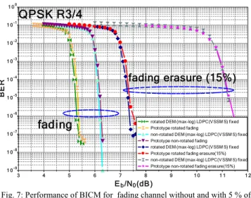
A comparison of simulatedperformance andmeasured performance in terms of BER of the designed BICM for a QPSK constellation, a code rate R=3/4and 64,800 bit frames, is presented in Fig. 7. The prototype shows quasi-identical performance when compared to fixed-point simulation for a maximum number of 25 decoding iterations.
3 4 5 6 7 8 9 1 0 1 1 1 2 Eb/N0(dB) 1 0-3 1 0-2 1 0-1 1 00 1 0-4 1 0-5 1 0-6 1 0-7 1 0-8 1 0-9 BE R
rotated DEM (max-log) LDPC(VSSM S) fixed Prototype rotated fading
non-rotated DEM (max-log) LDPC(V SSM S) fixed Prototype non-rotated fading
rotated DEM (max-log) LDPC(VSSM S) fixed Prototype rotated fading erasure(15%) non-rotated DEM (max-log) LDPC(V SSM S) fixed Prototype non-rotated fading erasure(15%) QPSK R3/4
fading
fading erasure (15%)
Fig. 7: Performance of BICM for fading channel without and with 5 % of erasures
CONCLUSION
BICM-ID shows best performance in the implementation guidelines of the DVB-T2 standard. In this paper, a
normalized MS decoder architecture based on a vertical layered schedule is presented. It enables an efficient exchange data process between the demapper and the decoder in the ID context. In addition, a prototype based on a FPGA device has been done to validate theperformanceof theproposedLDPCdecoderforDVB-T2.
ACKNOWLEDGMENT
The authors would like to thank Gerald Le Mestre for his help during the experimental setup design. This work has been carried out in the framework of the SME42 project of
the EUREKA's Eurostars programme.
REFERENCES
[1] E. Zehavi, “8-PSK trellis codes for a Rayleigh channel,” IEEE Trans. Commun., vol. 40, no. 5, pp. 873–884, May 1992. [2] X. Giraud, E. Boutillon, and J. C. Belfiore, “Algebraic tools to
build modulation schemes for fading channels,” IEEE Trans.
Commun., vol. 43, no. 3, pp. 938–952, May 1997.
[3] J. Boutros and E. Viterbo, “Signal space diversity: A power-
and bandwidth-efficient diversity technique for the Rayleigh fading channel,” IEEE Trans. Inform. Theory, vol. 44, no. 4,
pp. 1453–1467, July 1998.
[4] C. Abdel Nour and C. Douillard, “Improving BICM
performance of QAM constellations for broadcasting applications," 5th Int. Symp. on Turbo Codes and Related Topics, Lausanne, Switzerland, pp. 55-60, Sep. 2008.
[5] X. Li and J. Ritcey, “Bit-interleaved coded modulation with
iterative decoding,” IEEE Commun. Lett., vol. 1, no. 6, pp.
169–171, Nov. 1997.
[6] I. Abramovici and S. Shamai, “On turbo encoded BICM,” Ann.Telecommun., vol. 54, no. 3, pp. 225-234, March 1999. [7] DVB-T2, “Implementation guidelines for a second generation
digital terrestrial television broadcasting system (DVB-T2)”,
draft ETSI TR 102 831 3 V0.10.00, Nov., 2009.
[8] M. Li, C. Abdel Nour, C. Jégo and C. Douillard, “Design of
Rotated QAM Mapper/Demapper for the DVB-T2 Standard,”
SiPS 2009: IEEE workshop on Signal Processing Systems, October 2009.
[9] F. Guilloud, E. Boutillon, J. Tousch, J.L. Danger, “Generic
description and synthesis of LDPC decoder,” IEEE
Transactions on Communications, Vol. 55, n°11, pp 2084 - 2091, Nov. 2007.
[10] D. Hocevar, “A reduced complexity decoder architecture via
layered decoding of LDPC codes,” In Proc. Signal Processing
Systems SIPS 2004, pp 107–112, October 2004.
[11] J. Zhang and M. P. C. Fossorier, “Shuffled iterative decoding,” IEEE Trans. Commun., vol. 53, no. 2, pp. 209–213, Feb. 2005. [12] Z. Cui, Z. Wang, X. Zhang, Q. Jia, “Efficient Decoder Design
for High-Throughput LDPC Decoding,” IEEE Asia Pacific
Conf. on Circuits and Syst, pp. 1640-1643, Nov. 2008.
[13] C. Marchand, J.-B. Doré, L. Conde-Canencia, E. Boutillon, "Conflict Resolution by Matrix Reordering for DVB-T2 LDPC