HAL Id: hal-00552364
https://hal.archives-ouvertes.fr/hal-00552364
Submitted on 6 Jan 2011
(SCFC).
Jean-Paul Viricelle, Sorina Udroiu, Geoffroy Gadacz, Michele Pijolat,
Christophe Pijolat
To cite this version:
Jean-Paul Viricelle, Sorina Udroiu, Geoffroy Gadacz, Michele Pijolat, Christophe Pijolat.
Develop-ment of Single Chamber Solid Oxide Fuel Cells (SCFC).. Fuel Cells, Wiley-VCH Verlag, 2010, 10 (4),
pp.683. �10.1002/fuce.200900146�. �hal-00552364�
For Peer Review
Development of Single Chamber Solid Oxide Fuel Cells
(SCFC).
Journal: Fuel Cells
Manuscript ID: fuce.200900146.R1 Wiley - Manuscript type: Report
Date Submitted by the
Author: 28-Dec-2009
Complete List of Authors: VIRICELLE, Jean-Paul; Ecole des Mines, Centre SPIN Udroiu, Sorina; Ecole des Mines, SPIN/MICC
Gadacz, Geoffroy; Ecole des Mines, SPIN/MICC Pijolat, Michele; Ecole des Mines, SPIN/PROCESS Pijolat, Christophe; Ecole des Mines, SPIN/MICC
Keywords: Cathode, Conductivity, Fuel Cell, Low Temperature SOFCs, Screen Printing, Partial Oxidation, Performance Improvement
For Peer Review
Development of Single Chamber Solid Oxide Fuel Cells (SCFC).
J-P.. Viricelle*, S. Udroiu, G. Gadacz, M. Pijolat, C. Pijolat
Ecole Nationale Supérieure des Mines de Saint-Etienne, Centre SPIN, LPMG-UMR CNRS 5148, 158 cours Fauriel, 42023 Saint-Etienne Cedex 02 (France)
*Corresponding author: [email protected]
Abstract
Single Chamber Solid Oxide Fuel Cells (SCFC) have been prepared using an electrolyte as support (Ce0.9Gd0.1O1.95
named GDC). Anode (Ni-GDC) and different cathodes (Sm0.5Sr0.5CoO3 - SSC, Ba0.5Sr0.5Co0.2Fe0.8O3 - BSCF, and
La0.8Sr0.2MnO3 - LSM) were placed on the same side of the electrolyte. All the electrodes were deposited using
screen-printing technology. A gold collector was also deposited on the cathode to decrease the over-potential. The different materials and fuel cell devices were tested under propane / air mixture, after a preliminary treatment under hydrogen to reduce the as-deposited nickel oxide anode. The results show that SSC and BSCF cathodes are not stable in these conditions, leading to a very low open circuit voltage (OCV) of 150mV. Although LSM material isn’t the more adequate cathode regarding its high catalytic activity towards hydrocarbon conversion, ithas a better chemical stability
than SSC and BSCF. Ni-GDC-LSM SCFC devices were elaborated and tested; an open circuit voltage of nearly 750mVcould be obtained with maximum power densities around 20mW.cm-2 at 620°C, under air-propane mixture with C3H8/O2 ratio equal to 0.53 .
Keywords: BSCF, Fuel cell, GDC, LSM, Single chamber, SOFC, Solid oxide fuel cell, SSC.
1 Introduction
Solid Oxide Fuel cells have been studied intensively over the past two decades. Main efforts deal with the reduction of working temperature from 1000°C to around 600°C in order to reduce the cost due to the requirement of robust materials with adequate electrical and electrochemical properties, thermal stability, and due to the technological problems, especially sealing between anodic and cathodic chambers. More recently, a new type of device named “Single Chamber Solid Oxide Fuel Cells” (SCFC) has been proposed. In such device, contrary to conventional SOFC, anode and cathode are exposed to a gas mixture of fuel (hydrocarbon) and oxidant (air) so that no more sealing with electrolyte is necessary. Their operating principle is based on the different catalytic activities of anode and cathode: ideally, the anode has to be active for the oxidation of fuel while the cathode should only present a strong electro-activity for oxygen reduction. Most significant and initial developments of SCFC devices were performed by T. Hibino and co-workers who proposed a review on SCFC in [1]. In the first developments of SCFC devices [2-4], materials used in conventional SOFC were used, namely YSZ for electrolyte, Ni-YSZ cermet anode and LSM (La0.8Sr0.2MnO3) cathode. As for conventional SOFC, such materials are now more and more replaced in
order to significantly reduce the operating temperature while increasing or, at least maintaining performances. YSZ electrolyte is substituted by doped ceria oxide either with Gadolinium (GDC) or samarium (SDC). Most of the anodes are constituted by a cermet of previous electrolyte with nickel. For cathode, the trend is to use doped perovskites with cobalt, either Ba0.5Sr0.5Co0.8Fe0.2O3-δ (BSCF, [5]) or
Sm0.5Sr0.5CoO3 (SSC, [6-8]), or La0.5Sr0.5CoO3 (LSC, [9]). With such SCFC devices, depending on the cell
microstructure, geometry and flow conditions, maximum power densities of 700mW/cm2 at 600°C have been
reached [7]. However, such high values are not so easily obtained: even for fixed materials, all experimental details such as flow geometry [8] or the way of the SCFC initialization [10] for example, have significant influence on the performances.
The aim of this study was to investigate the influence of experimental parameters, especially flow composition, in our testing bench conditions. More comprehensive studies on SCFC working principle were reported by Hibino [1] and Haile [7]. In the present paper, we present our recent results concerning SCFC developments, with GDC electrolyte, Ni-GDC anode and LSM or SSC or BSCF as cathode. Materials characterizations and SCFC evaluations were performed under propane / oxygen mixtures. Among possible hydrocarbons, propane was chosen because it can be cracked at lower temperature than methane, and it can also produce more hydrogen by partial oxidation due to its higher carbon number (Eq. (1)).
Formatted: Font color: Blue Formatted: Font color: Auto Formatted: Font color: Auto Formatted: Font color: Auto Formatted: Font color: Blue Formatted: Tabs: 141.75 pt, Left + 481.95 pt, Right
Deleted: , with a thickness of 10 µm.
Deleted: Only Deleted: cathode
Deleted: can be used in this case, Deleted: showing a
Deleted: , and Deleted:
Deleted: the corresponding SCFC of Deleted: 500
Deleted: . Polarization measurements show a maximal Deleted: density Deleted: of Deleted: 1 Deleted: running Deleted: 600mW Deleted: 550 Deleted: were Deleted: are Deleted: a Deleted:
1
2
3
4
5
6
7
8
9
10
11
12
13
14
15
16
17
18
19
20
21
22
23
24
25
26
27
28
29
30
31
32
33
34
35
36
37
38
39
40
41
42
43
44
45
46
47
48
49
50
51
For Peer Review
2C3H8 + 3O2 → 6CO + 8H2 (1)2 Experimental
2.1 Materials, SCFC preparation
The electrolyte material was made using a starting commercial powder (®NexTech Materials Ltd) of gadolinium doped ceria (Ce0.9Gd0.1O1.95 named GDC), having a specific area around 9 m2/g. The particle size
is in the range 0.1-10µm with a mean size (d50) around 0.5µm. The powder was pressed into pellets
(100MPa, 2min) and sintered at 1350°C for 4 hours with an intermediate step at 1200°C during 6 hours. Temperature rates were 10°C/min for both heating and cooling. Final pellets have a diameter of 19mm and a thickness of 0.8 mm. Their relative density is around 92%.
Anode cermet was prepared from a mixture of 60%wt NiO (Sigma Aldrich) and 40%wt GDC. The initial NiO powder having a specific area around 3-4 m2/g was strongly agglomerated and was ball-milled in ethanol. The solvent was then evaporated while stirring and the resulting powder was passed through a 100µm screen sieve. The NiO powder particles size was then comparable to the one of GDC powder. The two powders were then mixed and ground in a mortar and pestle. Then, commercial binder and solvent were added to obtain an ink for screen-printing. The ink was homogenised with an ®Ultra-Turrax dispersion tool. The anode layer of 6*6 mm2 was then deposited by screen-printing technology on the previously described GDC pellet. To study the influence of electrode thickness, the number of deposited layer was varied, with an intermediate drying step at 130°C during 10 minutes between each deposit. The deposited filmswere fired at 1200°C for 2h, resulting in a porous anode layer with a thickness of either around 10µm (1 layer), 20µm (2 layer) or 40µm (4 layers). In order to activate the anode, reduction of nickel oxide was performed by thermal treatment in hydrogen. This part is detailed in paragraph 3.1.
Cathode was prepared using a similar process as for the anode. The powders were passed though a 100 µm screen sieve, and then mixed with a binder and a solvent to obtain an ink. Cathodes layers were also deposited using screen-printing. Three materials were used: La0.8Sr0.2MnO3 (named LSM) and
Sm0.5Sr0.5CoO3 (named SSC), commercial powders from ®NexTech Materials Ltd, and an in-house powder
supplied by IRCELYON laboratory (France), Ba0.5Sr0.5Co0.2Fe0.8O3 (named BSCF). Considering their
thermal stability, these cathodes were fired at 1200°C, 1000°C and 950°C for LSM, BSCF and SSC respectively.
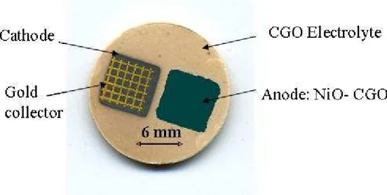
Anode and cathode were successively deposited and fired as reported previously, on the same side of the electrolyte pellet. The space between the two square electrodes is around 1mm. For SCFC performances tests, a gold current collector was deposited on the cathode. This collectors consist in a grid (line space of 0.5mm) deposited by screen-printing, using a commercial gold paste. It was fired after deposition, at 900°C during 20 minutes. A SCFC prototype can be seen in Figure 1.
2.2 Material characterization, fuel cell performance test
Prior to fuel cell performances tests, materials were characterized in regards of their electrical conductivity, catalytic activity and thermal stability.
Electrical conductivity of anode and cathode was measured according to Van Der Pauw method [11]. Particular samples supporting only the anode or the cathode on the GDC pellet were prepared, using the same elaboration process and parameters as described in previous part. Four thin platinum wires were stuck to the border of the studied layer with a platinum paste. These wires were connected to conventional electrical equipment to monitor current and voltage according to Van Der Pauw methodology. For cathode materials, measurements were conducted in air in the range 20-600°C. For anode, to avoid nickel re-oxidation, air-propane mixture was set in the bench after the reduction process made in hydrogen.
Catalytic activity of cathodes materials was investigated in a fixed bed reactor, towards propane conversion. The same quantity of cathode material in the form of powder dispersed in alumina was introduced to have comparative results. Propane conversion was measured thanks to a mass spectrometer coupled with a micro gas chromatograph (µGC-MS) placed at the bench outlet. Effectively, as the SCFC principle is based on the difference of catalytic activity of anode and cathode, cathode materials have to be the less active as possible with the hydrocarbon; they should only present a strong electrochemical activity towards oxygen reduction.
Anode and cathode thermal stability was investigated in the SCFC running conditions, after exposure to air-propane mixtures, by X-Ray diffraction. For cathodes, same characterizations were performed after the hydrogen treatment of the anode in order to control if they can withstand it.
Deleted: In fact, generally speaking, propane can be cracked more easily than methane, and can also produce more hydrogen by partial oxidation (Eq. (1)).¶ ¶ 2C3H8 + 3O2 → 6CO + 8H2 (1)¶ Deleted: support Deleted: of Deleted: , and Deleted: was Deleted: around Deleted: in nickel Deleted: IRCELyon
Deleted: and platinum Deleted: s Deleted: were Deleted: respectively Deleted: and anode Deleted: These Deleted: and platinum Deleted: They were Deleted: simultaneously Deleted: 7 Deleted: s
1
2
3
4
5
6
7
8
9
10
11
12
13
14
15
16
17
18
19
20
21
22
23
24
25
26
27
28
29
30
31
32
33
34
35
36
37
38
39
40
41
42
43
44
45
46
47
48
49
50
51
52
53
54
55
56
57
58
59
60
For Peer Review
SCFC performances were measured in a simple test bench consisting in a tubular furnace with a quartz tube. Electrical contacts are achieved thanks to gold wires in mechanical contact with gold collector on the cathode, and directly on the anode. In-situ activation of the anode was performed under a gas flow of 2% hydrogen balanced with argon. Then, after purging the system with nitrogen, the propane-air mixture was introduced. Three parameters were mainly investigated: total gas flow, C3H8/O2 ratio and the temperature. The gas flow was varied in the range 15 l/h to 50l/h: it is constituted of air-propane mixture and, for safety reasons, of an additional nitrogen flow in order to decrease the oxygen content to 12% in the bench. For example, total gas flow of 45l/h was composed of 30l/h of air-propane mixture and 15l/h of nitrogen. Effectively, in air, the explosive domain of air-propane mixtures is in the range 2.2-10% of propane. The decrease of oxygen content reduces this area which disappears for oxygen content lower than 12%. Another important parameter is air-propane ratio which was investigated in the range 10-16% vol. in propane, corresponding respectively to C3H8/O2 ratio in the range 0.53-0.95. It must be noted that the corresponding
ratio for partial oxidation of propane (Eq. 1) is 0.66. SCFC were tested in the temperature range 580-650°C.
These temperatures correspond to the regulated value of the furnace; depending on gas conditions, strong exothermic effect (overshoot of around 50°C) can occur during propane oxidation. If not specified, the reported temperatures are the furnace temperatures. A gas chromatograph and an infrared gas analyser performed gas analysis at the outlet of the test bench. The polarization curves of the SCFC devices were simultaneously measured in order to correlate performances with experimental conditions.
3 Results
3.1 Anode characterization
3.1.1 Anode reduction
The as-prepared NiO-CGO cermet anode has to be reduced before use in SCFC device. As in-situ reduction in air-propane mixture could not be easily achieved, a pre-treatment in H2 (2% balanced in Ar) was
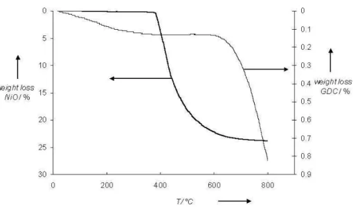
conducted. In order to define the adequate temperature range, thermogravimetric experiments were conducted with NiO and GDC powders. These powders were previously fired in air at 1200°C during two hours, as done for the screen-printed layers. Results reported in Figure 2 show that NiO begins to reduce at around 400°C, with a total reaction reached around 800°C corresponding to the theoretical weight loss of 21.4%. For GDC, a significant weight loss attributed to partial reduction of cerium IV in cerium III is observed from 600°C.
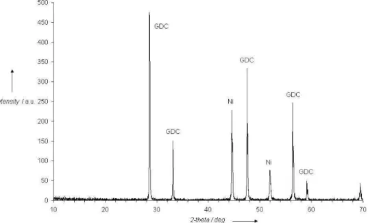
Taking into account previous results, various reduction conditions of the anode in the same gas have been tested in the temperature range 400-600°C, with varying duration from 30 minutes to few hours. Optimum condition to obtain a total reduction of NiO in our test bench, as shown by X-ray diffraction analysis (Figure 3), was found for a treatment of 600°C during 30 minutes.
3.1.2 Anode conductivity
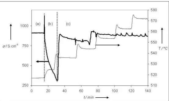
In order to check if the Ni-GDC anode has a satisfying electronic conductivity, conductivity measurements were performed as described in part 2.2. Results can be seen in Figure 4. Immediately after reduction at 600°C, the anode is stabilised under a nitrogen flow and the temperature is decreased to 520°C. During this period (domain (a) in figure 4), the conductivity is quite high around 900 S.cm-1. However, as soon as nitrogen is replaced by the flow of air-propane (C3H8/O2 ratio equal to 0.66), at 520°C, the conductivity
begins to decrease (domain b). The temperature is then raised to 535°C, and step by step up to 570°C. At 535°C, the conductivity comes back to its initial value and keeps a nearly constant and high value in the range 535-570°C (domain c). Same experiment (not shown in figure 4) was done with decreasing temperature and a similar behaviour was observed. At temperature lower than 530°C, the conductivity begins to collapse. After cooling back to room temperature, a green colour of the anode was observed at the surface, indicating a re-oxidation of nickel. These results validate the preparation process of the anode, but indicate that, for SCFC operating in our experimental conditions, temperature must be kept higher than 520°C to avoid nickel re-oxidation. A thermodynamic study was performed to check these experimental observations. A good agreement was obtained: calculations of the free Gibbs energy indicate that, among possible reactions of nickel and nickel oxide in the studied system, the predominant reaction at temperature lower than 535°C is the re-oxidation of nickel (Eq. (2)). At higher temperature, reduction of nickel oxide by propane is favoured (Eq. (3)).
Ni + 1/2O2 → NiO (2)
Formatted: Portuguese (Brazil) Formatted: Portuguese (Brazil) Formatted: Portuguese (Brazil) Deleted: the device
Deleted: s Deleted: initially Deleted: set at 3 Deleted: of Deleted: mixture Deleted: in Deleted: 55
Deleted: However, for safety reasons, an additional nitrogen flow of 15l/h was added in order to decrease the oxygen content to less than 12% in the bench. Effectively, in air, the explosive domain of air-propane mixtures is in the range 2.2-10% of propane. The decrease of oxygen content reduces this area which disappears for oxygen content lower than 12%.
Deleted: 500 Deleted: 700
Deleted: , in our experimental conditions
1
2
3
4
5
6
7
8
9
10
11
12
13
14
15
16
17
18
19
20
21
22
23
24
25
26
27
28
29
30
31
32
33
34
35
36
37
38
39
40
41
42
43
44
45
46
47
48
49
50
51
For Peer Review
1/3 C3H8 + NiO → Ni + CO + 4/3 H2 (3)3.2 Cathode characterization
3.2.1 Cathode conductivity
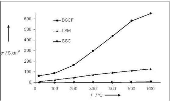
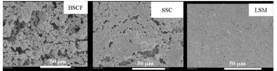
Electrical conductivity of the three studied cathode material, LSM, SSC and BSCF was measured under air in the range 20-600°C. Values reported in Figure 5 point out that SSC is the more conducted cathode with conductivity around 650 S.cm-1 at 600°C. The value for LSM and BSCF are respectively around 130 and 10 S.cm-1 at 600°C. The difference of electrical conductivity and especially the low value measured for BSCF cathode may be explained by the morphology of the layers: SEM observations (Figure 6) clearly point out that BSCF layer is quite more porous than SSC and LSM layers.
3.2.2 Cathode catalytic activity
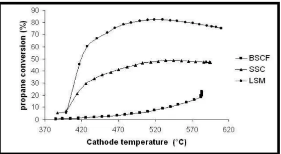
As reported previously, the efficiency of a cathode in a SCFC device is based on its low catalytic activity in regards of hydrocarbon conversion. Figure 7 represents propane conversion measured by the µGC-MS equipment at the outlet of the catalytic test bench versus temperature, for the three studied cathode material. Gas composition was set at a C3H8/O2 ratio equal to 0.66, thus corresponding to stoechiometric conditions of
partial oxidation (Eq. (1)).Results show a strong catalytic activity of LSM and SSC material in the range 450-600°C, quite higher than the one of BSCF. For this material, propane conversion increase slowly versus temperature but remains lower than 20% at 600°C, whereas it reaches respectively around 50% and 80% for SSC and LSM. Hence, considering catalytic activity criteria, BSCF is the more adequate cathode material for SCFC device.
3.2.3 Cathode thermal stability
Although interesting performances have been obtained with the studied cathode materials used in SCFC, the problem of SSC and BSCF stability has been reported previously [9-10]. Hence, it is necessary to investigate the thermal stability of the three cathode materials both in hydrogen (conditions of anode reduction) and air-propane (SCFC test conditions) gas flow.
After a thermal treatment similar to the anode reduction one, 600°C during 30 minutes in H2 (2% balanced in
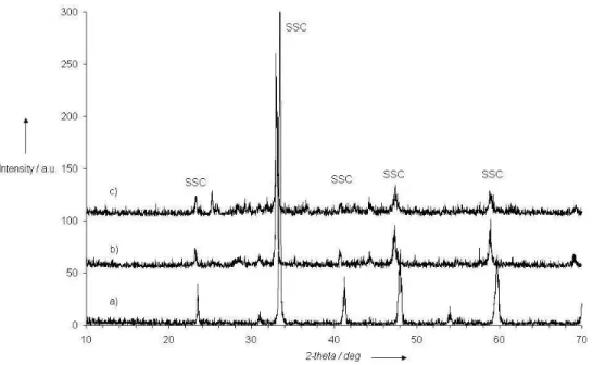
Ar), SSC and BSCF materials are degraded (Figure 8 for SSC). On the contrary, LSM material appears not affected,according to XRD analysis. Cathodes were also exposed to air-propane mixture at 630°C during 3 hours, without the reduction pre-treatment in H2. Effectively, other processes have been proposed in the
literature [10] to avoid anode initialization by hydrogen pre-treatment, in order to prevent cathode degradation. However, in our conditions, SSC and BSCF materials still present degradation, even if it appears less drastic than in hydrogen. LSM did not present any degradation in the same conditions.
In our actual preparation process of the SCFC device, both anode and cathode are deposited on the GDC support before the anode reduction treatment. Moreover, long term stability of BSCF and SCC materials is questionable in air-propane mixtures, at least in our experimental conditions. Hence, for the present study, it was only possible to use LSM material as a cathode, although we have confirmed that it is not the more adequate one, in regards of a too high catalytic activity for propane conversion.
3.3 (Ni-CGO / CGO / LSM) SCFC performance tests
3.3.1 Preliminary tests with a 20µm thick anode
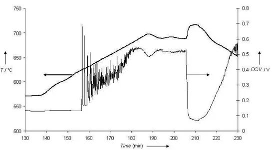
SCFC devices were tested in our bench as described in part 2.2. Preliminary tests were conducted with the sample prepared with a 20µm thick anode, a C3H8/O2 ratio equal to 0.55 and a total flow of 45l/h. Typical variation of the open circuit voltage (OCV) versus time and sample temperature can be seen in Figure 9. After the in-situ reduction of the anode at 600°C, the sample temperature is set at 580°C and the air-propane mixture is introduced. At this temperature, the OCV is quite low, in the range 100-200mV. Then, the temperature is increased to find the optimum value corresponding to the highest OCV. Figure 9 shows that the OCV increases sharply from around 620°C with also increasing exothermic effect, but the OCV presents some strong oscillations. It tends to stabilize around 500mV at 700°C ( sample temperature; furnace is at around 650°C). If the temperature is more increased, a sudden reduction of OCV value is observed, which is
Formatted: Portuguese (Brazil) Formatted: Portuguese (Brazil) Formatted: Portuguese (Brazil) Formatted: Portuguese (Brazil) Formatted: Portuguese (Brazil)
Formatted: Font: Not Bold Formatted: Font color: Blue
Formatted: Font: Not Bold Deleted: 2
Deleted: thermal stabi Deleted: li
Deleted: T
Deleted: was investigated Deleted: Deleted: . Deleted: ¶ Deleted: 6 Deleted: considering Deleted: a degradation Deleted: slower
Deleted: However, other processes may be proposed to overcome this inconvenient [8].
Deleted: Ni-CGO / CGO / LSM Deleted: 7
Deleted: , when the air-propane mixture is introduced
Deleted: It must be noted that a strong exothermic effect occurs when the fuel mixture is introduced, which can induce an overshoot of 50°C. Deleted: 7 Deleted: , Deleted: its Deleted: for Deleted: ,
Deleted: , and in the present conditions, OCV was around 500mV
1
2
3
4
5
6
7
8
9
10
11
12
13
14
15
16
17
18
19
20
21
22
23
24
25
26
27
28
29
30
31
32
33
34
35
36
37
38
39
40
41
42
43
44
45
46
47
48
49
50
51
52
53
54
55
56
57
58
59
60
For Peer Review
reversible with temperature decrease. Hence, for this sample (20µm thick anode) and in the present
experimental conditions, the optimum sample temperature is 700°C. In a previous paper [12], we have
shown that the optimal conditions are strongly dependant on experimental parameters.
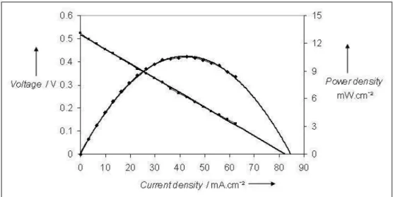
Voltage-current characteristic measured at these optimum conditions for this sample is reported in Figure 10. The effective area considered for calculation of current and power densities, taking into account our planar geometry (Figure 1), is the section of the electrolyte between the two electrodes, equal to 4.8mm2 (6*0.8mm2). A maximum power density of around 10 mW/cm2 is obtained. Characterisations of anode and cathode materials after the SCFC evaluation with various conditions were carried out by X-ray diffraction. For LSM, no significant modification could be detected. For Ni-CGO anode, results are more various depending on the history of the SCFC device. A partial nickel re-oxidation is sometimes observed, but it is not clear if it occurs during the fuel cell test, or during cooling down to ambient after test, which would be in agreement with observations made during anode conductivity characterisation (part 3.1.2). In other conditions, especially higher C3H8/O2 ratio (0.95), carbon deposition is observed on the anode.
3.3.2 Influence of experimental parameters on outlet gas composition
The influence of C3H8/O2 ratio and of total gas flow was investigated in more detail thanks to gas analysis at
the bench outlet. Thick anode sample (40µm) were used is this part of the study. For this sample, the optimum SCFC temperature was shifted to 620°C in conditions similar to previous ones (C3H8/O2 ratio equal
to 0.55 and a total flow of 45l/h). Hence, this sample temperature was fixed for following tests. Influence of C3H8/O2 ratio with a fixed total flow of 45l/h is shown in Figure 11. The concentration (vol. %) of main
constituents detected by the gas chromatograph are reported. Taking into account that the desired reaction is partial oxidation for CO and H2 production (Eq. (1)), comments are focused on these gases. Figure 11 shows
that, with increasing C3H8/O2 ratio, CO and H2 production decreases, contrary to concentrations of propane
conversion sub products. SFC performances were also observed to decrease, both OCV and power densities with increasing C3H8/O2 ratio, starting from a value of 0.53. The influence of total gas flow in the range
12-45 l/h was then investigated at 620°C and C3H8/O2 ratio fixed at 0.53. Figure 12 indicates that CO and H2
production increases with increasing flow higher than 25l/h. The same trend was also observed for SCFC performances. The polarization curve measured for our optimum conditions, 620°C, C3H8/O2 ratio 0.53, and
total gas flow of 45l/h can be seen in Figure 13. Main curve is obtained with a 40µm thick anode, while the insight shows measurements performed with a device having a 10µm thick anode. For the first one (40µm thick anode), OCV is around 780mV, and the maximum power density reaches 18mW/cm2. Hence performances are improved compared to previous tested device with a 20µm thick anode (Figure 10). Moreover, insight of Figure 13 shows that the 10µm thick anode device exhibits almost no more power density (0.035mW/cm2). Observations of SCFC samples tested in our optimum conditions (Figure 14)
reveals that the thin anode (10µm) is totally degraded with a black colour compared to grey colour of safe nickel anode. Strong exothermic effect due to high anode reactivity can explain this phenomenon. Hence, for fixed gas conditions (composition, flow), the thickness of the anode is of crucial importance for SCFC performances.
4 Conclusions
A SCFC device with a simple coplanar geometry of the electrodes was developed. The feasibility of operating in air-propane mixture was confirmed. However, with the actual configuration of SFC device (LSM-GDC-Ni) and test bench (furnace and gas feed geometry), limited performances were recorded. The maximum power density that we could obtain is around 20mW/cm2. Considering the too high catalytic
activity of LSM towards hydrocarbon conversion, and the low studied temperature around 600°C, SSC and BSCF cathode materials should lead to higher performances compared to LSM. However, stability of SSC and BSCF materials in air-propane mixtures could be hardly achieved. For nickel anodes, in our test conditions, a minimum temperature of 535°C was required to avoid its re-oxidation. Moreover, a minimum thickness is also probably required, regarding strong exothermic effects during propane oxidation. In order to improve SCFC performances, investigations on anode behaviour in running conditions is still continued, and modelling of the reactor geometry and chemical reactions rates around cathode and anode is required to optimize the experimental conditions.
Formatted: Font color: Auto
Formatted: Font color: Auto
Formatted: Font color: Blue
Formatted: Subscript Formatted: Font color: Blue Formatted: Font color: Blue Formatted: Font color: Blue
Formatted: Font color: Blue Formatted: Superscript Formatted: Font color: Blue Formatted: Font color: Blue Formatted: Font color: Blue Deleted: our
Deleted: demonstrated
Deleted: This temperature corresponds to the sample temperature, which is reported in Figure 7 and Figure 8. Deleted: was
Deleted: of our SOFC device, 700°C for a C3H8/O2 ratio equal to 0.55.
Effectively, these optimal conditions are strongly dependant on experimental parameters, in particular on fuel-air ratio, as shown in a previous paper [9]. The result Deleted: 8 Deleted: Deleted: running Deleted: ; Deleted: demonstrated Deleted: device Deleted: is Deleted: 10mW Deleted: such Deleted: are Deleted:
1
2
3
4
5
6
7
8
9
10
11
12
13
14
15
16
17
18
19
20
21
22
23
24
25
26
27
28
29
30
31
32
33
34
35
36
37
38
39
40
41
42
43
44
45
46
47
48
49
50
51
For Peer Review
References
[1] M. Yano, A. Tomita, M. Sano, T. Hibino, Solid State Ionics 2007, 177, 3351. [2] T. Hibino, S. Wang, S. Kakimoto, M. Sano, Solid State Ionics 2000, 127, 89.
[3] T.W. Napporn, X. Jacques-Bédart, F. Morin, M. Meunier, J. Electrochem. Soc. 2004, 151 [12], A2088. [4] D. Rotureau, J-P. Viricelle, C. Pijolat, N. Caillol, M. Pijolat, J. Eur. Ceram. Soc. 2005, 25, 2633. [5] Z. Shao, J. Mederos, W.C. Chueh, S.M. Haile, J. Power Sources 2006, 162, 589.
[6] L.J. Gauckler, et al., J. Power sources 2007, 171, 310.
[7] Y. Hao, Z. Shao, J. Mederos, W. Lai, DG Goodwin, S. Haile, Solid State Ionics 2006, 2013.
[8] I.C Stefan, C.P. Jacobson, S.J. Visco, L.C. De Jonghe, Electrochem; and Solid-State letters 2004, 7(7), A198. [9] M. Morales, S. Pinol, M. Segarra, J. Power Sources 2009, 194, 961.
[10] C. Zhang, Y. Zheng, R. Ran, Z. Shao, W. Jin, N. Xu, J. Ahn, J. Power Sources 2008, 179, 640. [11] .J. Van Der Pauw, Philips research reports 1958, 13, 1.
[12] JP Viricelle, C. Pijolat, B. Riviere, D. Rotureau, D. Briand, N.F. de Rooij, Sens. Actuators, B 2006 , 118, 263.
Remark:
*This paper has been presented at the Fundamental and Developments of Fuel Cells 2008 Conference (FDFC08) held in Nancy, France, on Dec. 10-12th, 2008.
Formatted: Font: Font color: Auto, (Asian) Chinese (PRC)
Formatted: English (U.K.)
Formatted: English (U.K.) Formatted: English (U.K.) Formatted: English (U.K.) Formatted: Font: Italic, English (U.K.)
Formatted: Font: Italic Formatted: Font: Bold Formatted: Font: (Asian) Chinese (PRC)
Formatted: Bullets and Numbering Formatted: Font: Italic
Formatted: Font: Bold
Formatted: Font: Font color: Auto, (Asian) Chinese (PRC)
Formatted: Portuguese (Brazil) Formatted: Portuguese (Brazil) Formatted: Font: (Asian) Chinese (PRC), (Other) Portuguese (Brazil) Formatted: French (France) Deleted: al.,
Deleted: L
Deleted: <#>C. Zhang, Y. Zheng, R. Ran, Z. Shao, W. Jin, N. Xu, J. Ahn, J.
Power Sources 2008, 179, 640.
1
2
3
4
5
6
7
8
9
10
11
12
13
14
15
16
17
18
19
20
21
22
23
24
25
26
27
28
29
30
31
32
33
34
35
36
37
38
39
40
41
42
43
44
45
46
47
48
49
50
51
52
53
54
55
56
57
58
59
60
For Peer Review
Figure caption
Fig. 1 SCFC prototype on GDC pellet with screen-printed electrodes.
Fig. 2 Thermogravimetric analysis of NiO and GDC powders under hydrogen (2% in Ar), temperature rising rate 10°C/min.
Fig. 3 XRD pattern of NiO-GDC anode after reduction 600°C-30min under hydrogen (2% in Ar) Fig. 4 Ni-GDC anode conductivity in air-propane mixture (C3H8/O2 = 0.66), versus temperature
Fig. 5 LSM, SSC and BSCF cathodes conductivity in air, versus temperature
Fig. 6 SEM of BSCF, SSC and LSM cathodes (as prepared layers)
Fig. 7 Catalytic activity measured as propane conversion rate with a µGC-MS,of BSCF, SSC and LSM cathodes (powders in a fixed bed reactor))
Fig. 8 XRD patterns of SSC cathode a) as prepared, b)after reduction 600°C-30min under H2 (2% in Ar), c) after
C3H8/O2 exposure at 630°C during 3 hours
Fig. 9 Open Circuit Voltage time dependence of a Ni-CGO / CGO / LSM SCFC under Air-propane (C3H8/O2=0.55),
versus time, with varying sample temperature
Fig. 10 Voltage-current characteristic of a Ni-CGO / CGO / LSM SCFC at 700°C (SCFC temperature) under Air-propane (C3H8/O2=0.55)
Fig. 11 Influence of C3H8/O2ratio on outlet gas composition, during SCFC test, at 620°C with a total gas flow of 45l/h.
Fig. 12 Influence of total gas flow on outlet gas composition, during SCFC test, at 620°C with a C3H8/O2 ratio set at
0.53.
Fig. 13 Voltage-current characteristic of a Ni-CGO / CGO / LSM SCFC at 620°C (SCFC temperature) under Air-propane (C3H8/O2=0.53), with a total gas flow of 45l/h. Influence of anode thickness: 40µm in main curve, 10µm in
insight.
Fig. 14 Photographs of SCFC devices with a 10µm (left) and 40µm (right) thick anode, after tests shown in figure 13.
Formatted: English (U.K.)
Formatted: English (U.K.)
Formatted: English (U.S.) Deleted: ¶ Deleted: 6 Deleted: 7 Deleted: 8 Deleted: Deleted:
1
2
3
4
5
6
7
8
9
10
11
12
13
14
15
16
17
18
19
20
21
22
23
24
25
26
27
28
29
30
31
32
33
34
35
36
37
38
39
40
41
42
43
44
45
46
47
48
49
50
51
For Peer Review
Fig. 1 SCFC prototype on GDC pellet with screen-printed electrodes. 131x65mm (96 x 96 DPI)
1
2
3
4
5
6
7
8
9
10
11
12
13
14
15
16
17
18
19
20
21
22
23
24
25
26
27
28
29
30
31
32
33
34
35
36
37
38
39
40
41
42
43
44
45
46
47
48
49
50
51
52
53
54
55
56
57
58
59
60
For Peer Review
Fig. 2 Thermogravimetric analysis of NiO and GDC powders under hydrogen (2% in Ar), temperature rising rate 10°C/min.
224x131mm (96 x 96 DPI)
1
2
3
4
5
6
7
8
9
10
11
12
13
14
15
16
17
18
19
20
21
22
23
24
25
26
27
28
29
30
31
32
33
34
35
36
37
38
39
40
41
42
43
44
45
46
47
For Peer Review
Fig. 3 XRD pattern of NiO-GDC anode after reduction 600°C-30min under hydrogen (2% in Ar) 256x159mm (96 x 96 DPI)
1
2
3
4
5
6
7
8
9
10
11
12
13
14
15
16
17
18
19
20
21
22
23
24
25
26
27
28
29
30
31
32
33
34
35
36
37
38
39
40
41
42
43
44
45
46
47
48
49
50
51
52
53
54
55
56
57
58
59
60
For Peer Review
Fig. 4 Ni-GDC anode conductivity in air-propane mixture (C3H8/O2 = 0.66), versus temperature 205x123mm (96 x 96 DPI)
1
2
3
4
5
6
7
8
9
10
11
12
13
14
15
16
17
18
19
20
21
22
23
24
25
26
27
28
29
30
31
32
33
34
35
36
37
38
39
40
41
42
43
44
45
46
47
For Peer Review
Fig. 5 LSM, SSC and BSCF cathodes conductivity in air, versus temperature 176x105mm (96 x 96 DPI)
1
2
3
4
5
6
7
8
9
10
11
12
13
14
15
16
17
18
19
20
21
22
23
24
25
26
27
28
29
30
31
32
33
34
35
36
37
38
39
40
41
42
43
44
45
46
47
48
49
50
51
52
53
54
55
56
57
58
59
60
For Peer Review
Fig. 6 SEM of BSCF, SSC and LSM cathodes (as prepared layers) 247x65mm (150 x 150 DPI)
1
2
3
4
5
6
7
8
9
10
11
12
13
14
15
16
17
18
19
20
21
22
23
24
25
26
27
28
29
30
31
32
33
34
35
36
37
38
39
40
41
42
43
44
45
46
47
For Peer Review
Fig. 7 Catalytic activity measured as propane conversion rate with a µGC-MS,of BSCF, SSC and LSM cathodes (powders in a fixed bed reactor))
150x81mm (108 x 109 DPI)
1
2
3
4
5
6
7
8
9
10
11
12
13
14
15
16
17
18
19
20
21
22
23
24
25
26
27
28
29
30
31
32
33
34
35
36
37
38
39
40
41
42
43
44
45
46
47
48
49
50
51
52
53
54
55
56
57
58
59
60
For Peer Review
Fig. 8 XRD patterns of SSC cathode a) as prepared, b)after reduction 600°C-30min under H2 (2% in Ar), c) after C3H8/O2 exposure at 630°C during 3 hours
256x159mm (96 x 96 DPI)
1
2
3
4
5
6
7
8
9
10
11
12
13
14
15
16
17
18
19
20
21
22
23
24
25
26
27
28
29
30
31
32
33
34
35
36
37
38
39
40
41
42
43
44
45
46
47
For Peer Review
Fig. 9 Open Circuit Voltage time dependence of a Ni-CGO / CGO / LSM SCFC under Air-propane (C3H8/O2=0.55), versus time, with varying sample temperature
205x114mm (96 x 96 DPI)
1
2
3
4
5
6
7
8
9
10
11
12
13
14
15
16
17
18
19
20
21
22
23
24
25
26
27
28
29
30
31
32
33
34
35
36
37
38
39
40
41
42
43
44
45
46
47
48
49
50
51
52
53
54
55
56
57
58
59
60
For Peer Review
Fig. 10 Voltage-current characteristic of a Ni-CGO / CGO / LSM SCFC at 700°C (SCFC temperature) under Air-propane (C3H8/O2=0.55)
186x95mm (96 x 96 DPI)
1
2
3
4
5
6
7
8
9
10
11
12
13
14
15
16
17
18
19
20
21
22
23
24
25
26
27
28
29
30
31
32
33
34
35
36
37
38
39
40
41
42
43
44
45
46
47
For Peer Review
Fig. 11 Influence of C3H8/O2 ratio on outlet gas composition, during SCFC test, at 620°C with a total gas flow of 45l/h.
109x72mm (150 x 150 DPI)
1
2
3
4
5
6
7
8
9
10
11
12
13
14
15
16
17
18
19
20
21
22
23
24
25
26
27
28
29
30
31
32
33
34
35
36
37
38
39
40
41
42
43
44
45
46
47
48
49
50
51
52
53
54
55
56
57
58
59
60
For Peer Review
Fig. 12 Influence of total gas flow on outlet gas composition, during SCFC test, at 620°C with a C3H8/O2 ratio set at 0.53.
112x89mm (115 x 105 DPI)
1
2
3
4
5
6
7
8
9
10
11
12
13
14
15
16
17
18
19
20
21
22
23
24
25
26
27
28
29
30
31
32
33
34
35
36
37
38
39
40
41
42
43
44
45
46
47
For Peer Review
Fig. 13 Voltage-current characteristic of a Ni-CGO / CGO / LSM SCFC at 620°C (SCFC temperature) under Air-propane (C3H8/O2=0.53), with a total gas flow of 45l/h. Influence of anode thickness:
40µm in main curve, 10µm in insight. 232x164mm (96 x 96 DPI)
1
2
3
4
5
6
7
8
9
10
11
12
13
14
15
16
17
18
19
20
21
22
23
24
25
26
27
28
29
30
31
32
33
34
35
36
37
38
39
40
41
42
43
44
45
46
47
48
49
50
51
52
53
54
55
56
57
58
59
60
For Peer Review
Fig. 14 Photographs of SCFC devices with a 10µm (left) and 40µm (right) thick anode, after tests shown in figure 13. 120x56mm (96 x 96 DPI)