HAL Id: tel-03186032
https://tel.archives-ouvertes.fr/tel-03186032
Submitted on 30 Mar 2021HAL is a multi-disciplinary open access archive for the deposit and dissemination of sci-entific research documents, whether they are pub-lished or not. The documents may come from teaching and research institutions in France or abroad, or from public or private research centers.
L’archive ouverte pluridisciplinaire HAL, est destinée au dépôt et à la diffusion de documents scientifiques de niveau recherche, publiés ou non, émanant des établissements d’enseignement et de recherche français ou étrangers, des laboratoires publics ou privés.
parameter modelling
Geneviève Mkadara
To cite this version:
Geneviève Mkadara. Contribution to the monitoring of hydraulic axial piston pumps for helicopters, with special focus on lumped parameter modelling. Mechanics of materials [physics.class-ph]. INSA de Toulouse, 2020. English. �NNT : 2020ISAT0020�. �tel-03186032�
THÈSE
En vue de l’obtention du
DOCTORAT DE L’UNIVERSITÉ DE TOULOUSE
Délivré par l'Institut National des Sciences Appliquées de
Toulouse
Présentée et soutenue par
Geneviève MKADARA
Le 8 octobre 2020
Contribution à la surveillance des pompes hydrauliques à pistons
axiaux pour les hélicoptères, avec un accent particulier sur la
modélisation à paramètres localisés
Ecole doctorale : MEGEP - Mécanique, Energétique, Génie civil, Procédés Spécialité : Génie mécanique, mécanique des matériaux
Unité de recherche :
ICA - Institut Clément Ader
Thèse dirigée par
Jean-Charles MARE
Jury
M. Giovanni JACAZIO, Rapporteur M. Esteban CODINA MACIà, Rapporteur
Mme Christine PRELLE,
M. Marc BUDINGER, Examinateur M. Jean-Charles MARE, Directeur de thèse M. Gregor PAULMANN, Co-directeur de thèse
Contribution to the monitoring of hydraulic ax ial piston pumps for helic opters, with special foc us on lumped parameter modelling
MK A D A R A G. 1
If someone had told me five years ago that I would write a preface for my doctoral thesis manuscript, I wouldn't have believed it. Well, it seems that, despite everything, I really have done a Ph.-D... And there has to be a preface to the manuscript! Many pe ople have supported me during these years of research, and have allowed me to complete this work. I can't name them all and I hope no one will take offence.
First of all, I would like to thank Prof. Jean -Charles Maré and Gregor Paulmann, who have always pushed me to do better, who have both taught me a lot and given me so much good advice both professionally and privately. Thank you for always being attentive to my ideas. I think I have become a better person, certainly more pragmatic, in your contact.
Next, I would like to thank Bruno C., Thomas B. and Olivier N., as well as all my team at Airbus Helicopters, for all the help they gave me during my research. I am happy to have been part of this very nice team.
I would also like to thank the industrial partn er we cooperated with during the thesis, for his reactivity and for all his precious advice.
Thanks to Odile, Marion, and my family for the welcome and the desserts. Many thanks to my roommates and all of my friends (from IC A, INSA, Airbus Helicopters as well as the Swing dance team) for the moral support, dancing and laughter. I don't think I could have reached this far without you.
And then, to all the musicians out there, thank you for the music you bring to the world. You certainly don't know it, but yo u have contributed greatly to the writing of this manuscript.
2 Contribution to the monitoring of hydraulic ax ial piston pumps for helic opters, with special foc us on lumped parameter modelling
MK A D A R A G.
Si quelqu’un m’avait dit il y a cinq ans que j’écrirais une préface pour mon manuscrit de thèse de doctorat, je ne l’aurais pas cru. Et bien il semble que, malgré tout, j’ai réellement fait un doctorat… Et il faut bien une préface au manuscrit ! Beaucoup de personnes m’ont soutenue pendant ces années de recherche, et m’ont permis d’aller au bout de ce travail. Je ne peux pas les citer tous et j’espère que personne n’en prendra ombrage.
Je souhaite remercier tout d’abord Pr. Jean-Charles Maré et Gregor Paulmann, qui m’ont toujours poussé à fai re mieux, qui m’ont tous deux beaucoup appris et donné tant de bons conseils tant professionnels que privés. Merci de vous être toujours montré attentif à mes idées et ressentis. Je pense être devenue une meilleure personne, certainement plus pragmatique, à votre contact.
Je tiens ensuite à remercier Bruno C., Thomas B. et Olivier N ., ainsi que toute mon équipe à Airbus Helicopters, pour toute l’aide qu’ils m’ont fourni pendant ma recherche. Je suis heureuse d’avoir pu faire partie de cette très sympathique équipe.
Je souhaite aussi remercier le partenaire industriel avec qui nous avons coopéré pendant la thèse, pour sa réactivité et pour tous ses pré cieux conseils.
Merci à Odile, Marion et ma famille pour l’accueil et les desserts. Merci beaucoup à mes colocataires ainsi qu’à tous mes amis (de l’ICA, de l’INSA, d’Airbus Helicopters et du Swing) pour le soutien moral, la danse et les rires. Je ne pense pas que j’aurais pu venir à bout de ce travail sans vous.
Et puis, à tous les musiciens qui vivent et ont un jour vécu , merci pour la musique que vous apportez au monde. Vous ne le savez certainement pas, mais vous avez grandement contribué à l’écriture d e ce manuscrit.
Contribution to the monitoring of hydraulic ax ial piston pumps for helic opters, with special foc us on lumped parameter modelling
MK A D A R A G. 3
This dissertation presents a contribution to helicopter axial piston pump monitoring through modelling and simulation. A lumped -parameter model of such pump is developed to serve as a virtual test bench for monitoring studies. A s lumpedparameter models of axial piston pumps are less detailed than distributed -parameter models, the author proposes improvements of lumped --parameter modelling state-of-the-art, focusing on the monitoring industrial need. The proposal concentrates on t he pressure compensator simulation in degraded conditions, and on the slipper/swashplate leakage computation through a variable gap height. The developed pump model is compared to experimental data. Then , a graphical tool is proposed, which allows for the isolation of pump degradation within the hydraulic system. The study is concluded by recommendations for increasing the maturity level of the proposed monitoring approach.
Résumé
Cette thèse présente une contribution à la surveillance des pompes à pistons axiaux des hélicoptères par modélisation et simulation. Un modèle de pompe à paramètres localisés est développé pour servir de banc d'essai pour les études de surveillance. L'auteure propose des améliorations de l'état de l'art de la modélisation à paramètres localisés des pompes à pistons axiaux, en se concentrant sur le besoin industriel de surveillance. La proposition se concentre sur la simulation du régulateur de pression dans des conditions dégradées, et sur le calcul des fuites de patin/plateau à tra vers un jeu de hauteur variable. Le modèle de pompe développé est comparé à des données exp érimentales. Un outil graphique est ensuite proposé. Cet outil permet d'isoler la dégradation de la pompe dans le système hydraulique. L'étude se termine par des rec ommandations pour augmenter le niveau de maturité technologique de l'approche proposée.
4 Contribution to the monitoring of hydraulic ax ial piston pumps for helic opters, with special foc us on lumped parameter modelling MK A D A R A G. Preface ... 1 Préface ... 2 Abstract ... 3 Résumé ... 3 Content ... 4 1. General introduction ... 7
1.1. About maintenance: benefits of monitoring ... 7
1.2. H/C hydraulics: a help to fly ... 9
1.3. H/C hydraulic pumps and maintenance ... 11
1.4. Manuscript organization ... 14
2. Improvement of lumped parameter modelling of axial piston pumps ... 15
2.1. Introduction ... 15
2.2. Model architecting ... 20
2.2.1. Architecting process... 20
2.2.2. Definition of architecture structure and causality ... 22
2.3. About Bond-Graphs ... 25
2.4. Generic Ld0 axial-piston pump model ... 27
2.4.1. Fluid compressibility ... 28
2.4.2. Flow through orifices ... 28
2.4.3. Generic pump main clearance models ... 30
2.4.4. Contact management models ... 33
2.5. Improvement of pressure compensator modelling ... 35
2.5.1. Literature review ... 36
2.5.2. Compensator model for condition monitoring - implementation proposal ... 44
2.5.3. Verification of compensator model and discussion ... 49
2.6. Proposition of a variable slipper/swashplate gap height model ... 55
Contribution to the monitoring of hydraulic ax ial piston pumps for helic opters, with special foc us on lumped parameter modelling
MK A D A R A G. 5 2.7. Conclusion ... 73 3. Model assessment ... 77 3.1. Introduction ... 77 3.2. Experiments ... 78 3.2.1. Test procedure ... 79
3.2.2. Test bench set up ... 80
3.2.3. Analysis of the measurements ... 83
3.3. Model assessment ... 94
3.3.1. Test bench model ... 94
3.3.2. Pump model evaluation process ...102
3.4. Conclusion ...111
4. Helicopter axial piston pump monitoring ...115
4.1. General considerations ...115
4.2. Case pressure as a monitoring means ...116
4.2.1. Theoretical considerations ...116
4.2.2. Pump model simulations ...117
4.2.3. Pump vs. hydraulic system degradation ...118
4.3. Feasibility study of the proposed approach ...122
4.4. About implementation on helicopter ...132
4.4.1. Measurement conditions on H/C ...132 4.4.2. Other considerations ...133 4.5. Conclusion ...134 5. General conclusion ...137 References ...141 Abbreviations ...148 Definitions ...149 Nomenclature ...150 List of figures ...154 List of tables ...156
6 Contribution to the monitoring of hydraulic ax ial piston pumps for helic opters, with special foc us on lumped parameter modelling
MK A D A R A G.
A-2 Test bench photos ... A-3 Test bench data (hoses and sensor locations) ... A-4 Test pump ATP results ... A-5 Additional graphs from experiments ... A-6 Published papers ...
Contribution to the monitoring of hydraulic ax ial piston pumps for helic opters, with special foc us on lumped parameter modelling
MK A D A R A G. 7
1. General introduction
Prior to anything, it is brought to the readers’ attention that the present work is the fruit of the cooperation of the Institut Clément Ader (ICA) public laboratory and Airbus Helicopters (AH), via an Industrial Convention of Training through Research (in French, CIFRE1). The research, started in May 2017, focuses on
monitoring of helicopter hydraulic pumps, with the aid of modelling and simulation. The rationale behind the present research is introduced hereafter. For information, the published scientific documents are provided in Annex A-6.
1.1. About maintenance: benefits of monitoring
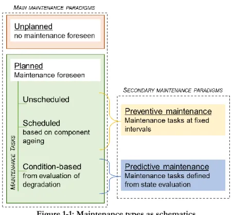
Maintenance is defined as “the work needed to keep a road, building, machine, etc. in good condition”2. In practice, two main paradigms can be highlighted:
unplanned and/or planned maintenance. In the first paradigm, the health of the product is ignored and the product is replaced whe n it fails. The second one acknowledges that some products (which can be systems, subsystems, equipment, components, etc.) require maintenance. As maintenance is deemed necessary, verifications and modifications are made on the product throughout its life3 and
usage.
Planned maintenance involves three types of tasks: unscheduled, scheduled and condition-based. Unscheduled tasks are planned but without explicit consideration to product amount of service or life. Scheduled tasks are realised according to a schedule that is defined from product use or ageing. Condition-based maintenance tasks are triggered by the evaluation of the product degradation, whether through visual inspection or measurement of variables of interest (i.e. condition monitoring). In that manner, condition-based maintenance tasks are engaged only when necessar y, opposite to scheduled tasks. It is to be noted that unscheduled maintenance tasks are equivalent to condition -based ones when the monitored product has failed. It is considered within this dissertation
1 Conventions Industrielles de Formation par la Recherche.
2 Definition supplied by the Cambridge Dictionary.
8 Contribution to the monitoring of hydraulic ax ial piston pumps for helic opters, with special foc us on lumped parameter modelling
MK A D A R A G.
(although it is not the common definition at AH) that condition-based maintenance tasks are done prior to product failure.
Then, another pair of paradigms can be added to the first one: preventive against predictive maintenance. On th e one hand, preventive maintenance aims at avoiding unexpected failures by realizing maintenance tasks at fixed interval (service or life). On the other hand, predictive maintenance reduces downtime through optimized maintenance schedule. In this case, mai ntenance is anticipated by: 1) Monitoring the product condition (taking measurements and deducing health status), 2) Computing the remaining life or service (simulating an evolution model against statistical use rate of the product), and 3) Scheduling the next required maintenance task.
Figure 1-1 is proposed to summarize the described categorisation with two pairs of paradigms and three types of maintenance tasks.
Figure 1-1: Maintenance types as schematics
Preventive maintenance is the most common approach deployed in the aerospace industry to ensure flight safety, i ncluding at Airbus Helicopters. The amount of life or service is quantified using calendar time, start/stop cycles, number of landings or flight hours (FH), respectively. In practice, maintenance schedules are defined in terms of inspection intervals, ti me between overhaul (TBO), etc.
However, unexpected failures may occur. The related maintenance effort can ground a helicopter (H/C) for a long time, even more when the supply chain of
Contribution to the monitoring of hydraulic ax ial piston pumps for helic opters, with special foc us on lumped parameter modelling
MK A D A R A G. 9
spare parts or work force is disturbed and/or the H/C is operated in a remote place. In this context, introducing predictive maintenance will generate several benefits. By allowing anticipated order of spares and working schedules for crews, it improves aircraft availability and therefore clients’ satisfaction. For Airbus Helicopters itself, it increases the current knowledge on the effective service and the condition evolution of the product. Last but not least, it supports the continuous improvement of the design as well as early identification of the most frequent faults and failure mechanisms.
Several studies have been launched to study and propose condition -based maintenance solutions on H/C, see e.g. (Nesci, et al., 2020). AH has launched several projects to move towards condition-based maintenance. One of them, the present research, focuses on condition monitoring (CM) of H/C hydraulic pumps. The needs for hydraulics on helicopters as well as maintenance of hydraulic pumps are addressed in the next section.
1.2. H/C hydraulics: a help to fly
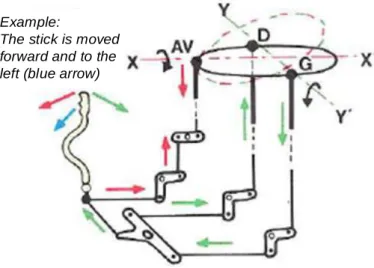
H/C attitude and trajectory are piloted by actions on the pitch of the main and tail rotor blades. To this end, pilots position three interfaces: the cyclic stick, the collective lever, and the pedals. On smaller helicopters without automatic flight control systems, these actions can be transmitted to the rotor s by pure mechanical linkage (i.e. mechanical flight controls) as can be seen on Figure 1-2. However, this is not only signalling because force is required to hold the position of the inceptors and balance aerodynamic loads. For larger weight helicopters equipped with automatic flight control systems for stabilization and guidance, it is no more possible for the pilot/automatic systems to apply and to maintain these forces. Assistance is therefore provided through mechanically -signalled, hydraulically supplied, position servo-actuators. Additionally, hydraulic power is sometimes used to supply some electro -hydraulic actuators that are connected to the mechanical linkage from the pilot to perform stability and control augmentation (e.g. on AS332, Tiger). In H/C with fly -by-wire flight control systems (e.g. NH90), pilot actions are exclusively transmitted through electrical links to servo actuators which remain hydraulically supplied (i.e. electro -hydraulic servo-actuators).
The loss of blade pitch control is mainly classified as a “catastrophic” event. To meet the corresponding reliability requirement (<10- 9 event/FH), the
hydraulic system is made redundant with segregated channels. As such, any failure of a given hydraulic system channel is classified as “major” (reliabi lity target <
10 Contribution to the monitoring of hydraulic ax ial piston pumps for helic opters, with special foc us on lumped parameter modelling
MK A D A R A G.
10- 5 event/FH) and leads to mission interruption or cancelling which means either
un-planned landing if in flight or H/C not available for the mission. Example:
The stick is moved forward and to the left (blue arrow)
Figure 1-2: Illustration of mechanical linkage from pilot stick to rotor swashplate, adapted from (Raletz, 2009, p. 49)
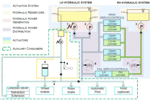
As displayed by the example given on Figure 1-3, the H/C hydraulic system is composed of generic elements (including main rotor-driven pumps or auxiliary/emergency electro pumps, by -pass valves, filters, check valves, pressure switches, accumulators, etc.) that are combined to meet the functional and the safety requirements. It is worth noting that, on Figure 1-3, left and right hydraulic system are hydraulically independent: a failure in one hydraulic system cannot propagate to the other system.
Hydraulic pumps are the power source of th e hydraulic system. As such, any loss of a main pump is classified as “major”, and leads in practice to cancel /abort the mission. Therefore deploying a predictive maintenance approach for hydraulic systems and their pumps in particular is an efficient mean to improve helicopter availability and safe operation. The next section focuses on hydraulic pumps in H/C, giving a glimpse of the importance of their maintenance.
Contribution to the monitoring of hydraulic ax ial piston pumps for helic opters, with special foc us on lumped parameter modelling
MK A D A R A G. 11
Figure 1-3: Example of a typical H/C hydraulic system (Coïc, 2017)
1.3. H/C hydraulic pumps and maintenance
The main hydraulic pumps used on AH H/C are driven by the engine. In nominal operating conditions, the pump rotating speed is consequently almost constant.
Two pump technologies are used on H/C: gear pumps and pressure regulated axial piston pumps. Compared with axial piston pumps, gear pumps are cheaper and have better reliability due to fewer internal parts. However, in order to provide a constant pressure source, t hey must be combined with additional components (e.g. pressure relief valve). Due to low er power efficiency and associated additional thermal control demands compared to pressure regulated axial piston pumps, this design is only selected for low power appl ications.
Pressure regulated axial piston pumps are chosen for high power applications and are the focus of this work. The regulation of these pumps is accomplished by a pure hydro-mechanical mechanism without any electrical element in the control loop. Such type of pump has three main hydraulic ports: suction, discharge, and case drain. The pump sucks in fluid from the tank at suction port and, after pressurization, delivers it into the hydraulic system at discharge port. Dynamic sealing between internal moving parts is performed with resort to calibrated clearances, which also enable lubrication. Consequent leakage flows are collected in the pump case and exit at the case drain port. In that manner, case drain port avoids the case pressure to rise and ena bles the heat produced by the pump energy losses to be evacuated. Dynamic external sealing is performed between the
12 Contribution to the monitoring of hydraulic ax ial piston pumps for helic opters, with special foc us on lumped parameter modelling
MK A D A R A G.
rotating drive shaft and the housing . The leakage here is mostly collected and dissipated by the additional seal drain port.
The function of the axial piston pump is to provide the users with fluid at a constant pressure, whatever the demanded flow. As a consequence, pump failure is defined here as the “inability of the pump to keep pressure at rated value in the hydraulic system” in the plann ed operational range. Pump degradation, prior to failure, can be detected during the overhauls that occur at fixed FH or year intervals. In between overhauls, t wo events are currently used at AH to try and detect pump failure:
- External droplet leakage at seal drain port observed during a visual inspection. This inspection mainly highlights seal wear, and not the internal state of the pump.
- Spontaneous light up of the “hydraulic pressure” indicator in the cockpit. This event happens when the system pressure goes out of a reference pressure zone for a certain time. However, pump failure is not the only reason for the system pressure rise or to drop (e.g. hose leak). In this light, this indicator only gives the information that something, which might be the pump, has already failed in the hydraulic system.
On latest H/C with increased avionic capabilities, the trend of the hydraulic system pressure evolution is also monitored, giving information of creeping degradation of the hydraulic system. None of these approaches allows to detect pump failure with certainty. As such, there is a need to develop new monitoring approaches for condition -based maintenance of hydraulic pumps on helicopters.
However, the wide range of possible operation environmental conditions (altitude as high as 7000m and temperature from -45 to +50°C) constrains monitoring approaches to solutions that are independent from ambient pressure and temperature. Another point to be considered is the diversity of types, operating conditions, and displa cement of pumps. As an example, Table 1-1 illustrates the range of axial piston pumps used in Airbus Helicopter fleet. The aim of the project is to develop a monitoring approach applicable to every axial piston pump of the fleet. As a consequence, any considered monitoring approach must use non pump-intrusive sensors: using intrusive sensors would mean designing the approach for one pump in particular.
Table 1-1: Key figures of axial piston pumps on AH fleet (Paulmann & Mkadara, 2018) Flow rate [L/min] Pressure [bar] Weight [kg] Max power consumption [W]
Range 8 to 60 103 to 210 1.1 to 5.6 1700 to 22000
Condition monitoring approaches for hydraulic pumps are already implemented on static applications (e.g. for industrial plant pumps: DMT PlantSafe®,
Contribution to the monitoring of hydraulic ax ial piston pumps for helic opters, with special foc us on lumped parameter modelling
MK A D A R A G. 13
Prüftechnik Vibnode®). A continuous extensive research work is undertaken to develop fault detection and diagnosis concepts for hydraulic pumps, e.g. (Succi & Chin, 1996) and (Torikka, 2011). However, in the Airbus Helicopters industrial context, the only necessity is to detect pump degradation on H/C level: there is no need to diagnose which part of the pump is the root cause of its failure.
Pump degradation generally leads to increased internal leakage, loss of pressure, increase of drive torque, abnormal vibration and/or rise of temperature. All five variables impacted by pump degradation (flow, pressure, torque, acceleration, and temperature, respectively) can be used to monitor the pump state.
Temperature measurement is very informative and could be used, but due to complex environmental constraints defined earlier, it was decided to leave it out the current study. This decision also comes from the fact that not a ll Airbus Helicopter H/C are equipped with temperature sensors in hydraulic systems, which makes the usage of this variable more difficult.
The highly vibratory helicopter environment is hardly reproducible on a ground test bench. As such, accelerations measurement, however commonly used for the study of rotating machinery, was also excluded of the current study.
Finally, drive torque measurement is highly intrusive and cannot be implemented without deep modification of the pump integration, which is why it was also left aside.
In this context and due to the current project constraints , priority has been given in this work to pump leakage monitoring. However, off-the-shelf flow sensors qualified for aerospace applications are rare and non -qualified ones are not accepted on H/C for safety reasons: most flow sensors use turbines put in the stream, that could get blocked by particles and generate unacceptable hydraulic resistance in the hydraulic circuit. Possible fracture of flow turbine, generating additional polluting particles, also ha s to be considered. The calibration of flow sensors over the larger temperature range of the H/C hydraulic fluid can also be seen as an obstacle. Given these considerations, pressure sensors are seen as the most attractive and feasible monitoring option.
As the overall pump leakage flows at case drain port, this research work aims at investigating pump monitoring through pressure measurement at case port. Thus, the industrial questions that this dissertation has to answer to are the following:
Q1. On H/C, can external case pressure sensors be used to detect pump degradation prior to failure?
14 Contribution to the monitoring of hydraulic ax ial piston pumps for helic opters, with special foc us on lumped parameter modelling
MK A D A R A G.
Q2. Can pump degradation be isolated from hydraulic system degradation when using one additional case pressure sensor only?
The merits of condition monitoring approaches can be assessed using degraded pumps. Unfortunately, the current maintenance process at AH does not make such pumps available for test (without contract ual changes between AH, the customers and suppliers). To go around this issue, pumps could be purposely degraded as discussed in Chapter 3. There are several examples of this approach in literature , e.g. (Chen, et al., 2016), however, it is very difficult to artificially create real in -service damage, and/or to cope with the multiple possible permutations of damages. In addition, this option is very destructive and costly. In the end, developing and simulating a realistic pump m odel has been found the most attractive alternative. Following this choice, scientific questions were identified:
Q3. What is the current state of the art for axial piston pump modelling? Q4. What improvements can be made from state of the art 1 -D pump
modelling in the view of condition monitoring and what do those improvements bring?
Q5. Is the pump model, running a simulated test in given operating conditions, able to reproduce the same result data and patterns as real tests made in the same operating conditions?
The research work performed to answer all scientific and industrial questions is reported in the following dissertation, using the structure introduced in the section 1.4.
1.4. Manuscript organization
In order to answer the five highlighted questions, the manuscript is organized as follows.
The discussion is opened on scientific questions in the second chapter, where improvements of the current axial piston pump lumped -parameter models state of the art are implemented and discussed.
The third chapter focusses on model validation to answer the question Q5. Then the fourth chapter answers the industrial questions on the basis of the developed and validated models.
Contribution to the monitoring of hydraulic ax ial piston pumps for helic opters, with special foc us on lumped parameter modelling
MK A D A R A G. 15
2. Improvement of lumped parameter modelling
of axial piston pumps
2.1. Introduction
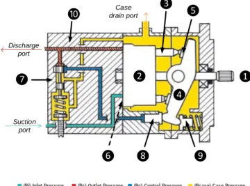
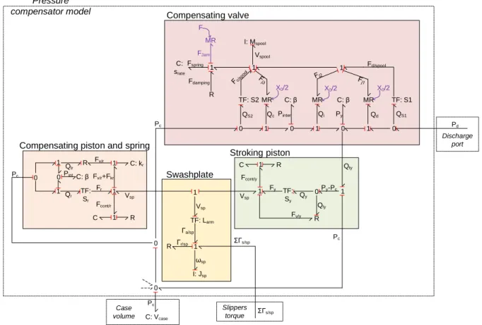
Most of the hydraulic axial piston pumps used on H/C are engine gearbox-driven, variable-displacement, and hydro-mechanically pressure -compensated (see pump cut displayed on Figure 2-1). The shaft is driven by an external source of mechanical power (the main gear box), leading the barrel into rotation with respect to the pump housing . The pistons , being placed inside the barrel cylinders, are forced into a combined rotating -translating motion due to their link to the inclined swashplate through the slippers . The pistons translation inside the barrel allows for the suction and discharge of the fluid through the barrel and valve-plate ports (not explicit on Figure 2-1 but marked ). The swashplate tilt, setting the pump displacement, is controlled through the pressure compensating device, composed of a compensating valve supplying flow to the stroking piston that reduce swashplate tilt when in extension. The last part of the compensating mechanism is the rate piston that tends to push back the swashplate to full displacement position in the pump housing (or case) . This pressure compensation mechanism makes the pump a source of near constant pressure. ❶ ❷ ❸ ❹ ❺ ❻ ❼ ❽ ❾
❿ drain portCase
Discharge port
Suction port
16 Contribution to the monitoring of hydraulic ax ial piston pumps for helic opters, with special foc us on lumped parameter modelling
MK A D A R A G.
The pump parts are completely immerged in hydraulic fluid inside the pump case. Designed-in leakages flow to the pump case and exit the housing at case drain port (as explained in section 1.3). There are many contact pairs between
moving bodies: piston/barrel, barrel /valve-plate, piston/slipper,
slipper/swashplate, stroking piston/case, rate piston/case, and compensating valve spool/case. They are lubricated through calibrated gaps. An increase of these built-in gaps and clearances intensifies the pump leakage, and provides an image of the pump wear.
A pump simulation model is developed to serve as a virtual test bench for the study of pump leakage through pressure measurement. This pump model is based on one of the H225 pumps, which characteristics are given on Table 1-1 hereafter. These characteristics originate from Acceptance Test Procedure (ATP) specifications, which define the proper behaviour of the pump upon reception by AH. During the acceptance tests, performed on each produced pump, key functions of the pump are obtained to demonstrate conformity of a production pump to characteristics of the pumps used for qualification.
Table 2-1: H225 axial piston pump steady state characteristics during ATP
Operating conditions Zero flow Full flow
Discharge pressure [bar] 175 ± 2 Min 160
Discharge flow [L/min] 0 27.0–28.0
Case drain pressure [bar] 0.8-1 0-1
Case drain flow [L/min] 0.3-1.5 Max 1.5
Fluid temperature [°C] 60 ± 5
Several approaches exist when considering modelling. T wo main paradigms can be highlighted: data driven models or physics-based models.
Data-driven (or knowledge-based) models are constructed from history data measured on the monitored system, and do not need any information about the system inner workings. On the contrary, physics -based models require a deep understanding of the system physics. In between both paradigm lay mixed approaches. Due to lack of history data , data-driven approaches are not implementable. Consequently, a physics -based approach is chosen.
In the physics-based paradigm, lumped -parameter approaches are distinguished from distributed-parameter approaches. Several model classifications exist: static or dynamic models, lumped or distribute d, against geometrical dimensions, etc.
A generic way to classify them all could be to change the usual short identification of the model type (0-D, 1-D or 3-D with D understood as geometrical Direction) which is often source of discussion and lack of mut ual understanding, to a new approach. Here we propose the notation 𝑋𝑧𝑦 where X is either L(umped) or D(istributed), y is either s(tatic) or d(ynamic) and z
Contribution to the monitoring of hydraulic ax ial piston pumps for helic opters, with special foc us on lumped parameter modelling
MK A D A R A G. 17
corresponds to the number of spatial dimensions considered for the variation of a physical variable. For example, a static lumped parameter model is classified as 𝐿𝑠0 while a distributed-parameter model of the flow in a pipe simplified in 2 -D with temporal variation of the upstream pressure will be classified as 𝐷2𝑑.
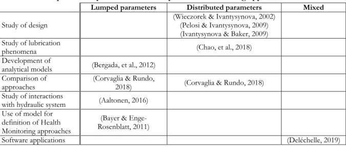
An extensive work has been done using lumped and distributed approaches for axial piston pumps. Table 2-2 shows that model purposes drive the choice of the modelling approach in literature.
Table 2-2: Examples of lumped and distributed parameters modelling approaches in literature
Lumped parameters Distributed parameters Mixed
Study of design (Wieczorek & Ivantysynova, 2002) (Pelosi & Ivantysynova, 2009)
(Ivantysynova & Baker, 2009) Study of lubrication
phenomena (Chao, et al., 2018)
Development of
analytical models (Bergada, et al., 2012)
Comparison of
approaches (Corvaglia & Rundo, 2018) (Corvaglia & Rundo, 2018)
Study of interactions
with hydraulic system (Aaltonen, 2016)
Use of model for definition of Health Monitoring approaches
(Bayer & Enge-Rosenblatt, 2011)
Software applications (Deléchelle, 2019)
In the light of physics-based approaches, AH does not need a highly detailed
𝐷∀𝑑 model, which would generate high computational loads, but a system -level one
that can be interfaced with already existing hydraulic system models. Th is point had driven the choice of a lumped-parameter approach for the present project.
However, when considering leakage modelling, 𝐿𝑑0 models are very light
compared to 𝐷∀𝑑 (Computational Fluid Dynamics or CFD models in fluid
mechanics) models, as can be seen on Table 2-3. A void cell means that no explicit mention of the physical effect is made in the cited paper.
18 Contribution to the monitoring of hydraulic ax ial piston pumps for helic opters, with special foc us on lumped parameter modelling
MK A D A R A G.
Table 2-3: Comparison of 3-D and 0-D models considering the pump main leakage paths
Interface Physical effect considered
(W ie cz or ek & Iva ntysy no va , 2002) (Pe lo si & Iva ntysy no va , 2009) (I va ntysyno va & Ba ke r, 200 9) (Ch ao , e t a l., 2018) (B er gad a, e t a l., 20 12) (A alto ne n, 2016) (1) : Piston/barrel type Tilt O O
Axial relative velocity O O Δ Δ
Eccentricity O O Δ
Spin O
Hydrodynamic forces O O
Varying gap length O O
Variable gap height O O
Solid to solid contact O O
Local thermal effects O O
Elastic deformations O
(2) : Slipper/
swashplate Tilt Relative velocity O O O O Δ Δ
Spin O
Hydrodynamic forces O
Variable gap O O
Solid to solid contact O
Local thermal effects O
Elastic deformations (3) : Barrel /
valve-plate Tilt Relative velocity O O O O Δ Δ Δ Δ
Timing grooves Δ
Hydrodynamic forces O O
Variable gap O O
Solid to solid contact O
Local thermal effects O O
Elastic deformations O
Legend:
Δ Lumped parameters O Distributed parameters
Bold Compared to experiments Italic Compared to CFD models
The observation of Table 2-3 gives rise to the scientific questions drawn in section 1.3 and reminded hereafter:
Q3. What is the current state of the art for axial piston pump modelling? Q4. What improvements can be made from state of the art 1 -D pump
modelling in the view of condition monitoring and what do those improvements bring?
Contribution to the monitoring of hydraulic ax ial piston pumps for helic opters, with special foc us on lumped parameter modelling
MK A D A R A G. 19
Q5. Is the pump model, running a simulated test in given operating conditions, able to reproduce the same result data and patterns as real tests made in the same operating conditions?
In this chapter, scientific questions Q3 and Q4 are answered focusing on two pump mechanisms (pressure compensator and slipper) , and improvements of the current state of the art of lumped -parameter modelling for axial piston pumps are discussed.
Scientific questions must be answered to. However, it is to be reminded that the model is initially developed to answer industrial questions . Thus, the model must meet industrial requirements with priority. The said requirements are defined in Table 2-4, where two types are highlighted: requirements from project purpose and requirements for durability. Durability is a very important consideration in the industry, where cooperation is needed in the everyday-work. It is very frequent for models to be shared with other company departments. Models can also be improved by several persons throughout their life, and it frequently happens that the final user of the model is not the model creator. However, the usual model development process (through step-by-step improvement) leads to prototype -like models. This type of model is hardly readable for any person other than the model creator.
Table 2-4: List of requirements for the pump model Project Purpose
Rq1 Shall simulate accurate behaviour for internal leakage, as well as suction and discharge pressure and flow Rq2 Shall be ready for simulation of pump degradation leading to increased internal leakage
Rq3 Shall enable to assess the monitoring approach Durability
Rq4 Shall be as generic as possible for further modifications, easy to assemble and modify (e.g. changing the number of pistons) Rq5 Shall allow for parameters and mathematical expression modifications
Rq6 Shall grant easy access to the basic components of the model
Rq7 Shall be usable as a digital twin, also as “plug and simulate” (only applicable to the whole pump model)
While Table 2-4 requirements defined under “project purpose” must be met through relevant modelling, “durability” requirements can be met through a proper model architecture. In the following section 2.2, the definition of the model architecture is presented. Section 2.3 gives basic information about Bond-Graphs, which formalism is used throughout this chapter to generated and explain the proposed models, and section 2.4 about generic lumped-parameter axial piston pump models. Then, sections 2.5 and 2.6 are focused on improvements to be made on the pressure compensator mechanism and on the slipper/swashpla te interface
20 Contribution to the monitoring of hydraulic ax ial piston pumps for helic opters, with special foc us on lumped parameter modelling
MK A D A R A G.
using the lumped-parameter approach and in the frame of condition monitoring. Finally, the chapter conclusion is given in section 2.7.
2.2. Model architecting
Model architecting is seldom discussed in lit erature as it a product of pragmatism. When architecture is needed, it is generally managed implicitly through the modellers’ experience. Distributed parameters models have explicit architecture as they tend to be the perfect image of the real product. Thi s is not the case of lumped-parameters models. In the case of the latter, a few published papers show architected models without discussing architecting or structuration methodology, e.g. (Poole, et al., 2011) or (Mancò, et al., 2002). In (Maré & Akitani, 2018) , the authors define an electro mechanical actuator model architecture derived from the product topology. The author of (Maré, 2019), after defining “Workshare” and “Capitalization” requirements, emphasizes that a topology-based architecture allows to partially meet those requirements as it helps model understanding and reuse. Then (Mkadara & Maré, 2020) stated that architecture should be fixed during the first phases of a project, however anticipating future modifications.
2.2.1. Architecting process
Model architecting is the process of suggesting/offering a structure to something that is initially abstract. Doing so, on e must think about the elements that compose the structure and the links between them. In this dissertation, it is chosen to define the structure elements as “blocks”, and t he links as “interconnections”. Blocks are box-like objects, meant be filled with models. Nevertheless, architecture must be defined in the early phases of a project. Thus, blocks must be ready for any evolution or upgrade : every possible interconnection to another block, through “ports”, must be prepared. A port is a lumped interface of a block to another, through which the interconnection passes.
Figure 2-2 illustrates a block that would contain a complete pump model. This pump block shows every pump ports and interfaces, including dynamics of the housing:
- For hydraulics: Suction ( 𝑠), Discharge (𝑑), and Case ports (𝑐) with pressure (𝑃𝑥) and volume flow rate ( 𝑄𝑥) at each port;
- For mechanics: Drive shaft (𝑚) and Base (𝑏) ports, with Torque (𝛤𝑥) and angular velocity (𝜔𝑥) at each port;
- The thermal port with temperature ( 𝑇𝑥) and heat flux (𝛷𝑥) power variables. The orientation of the arrows on Figure 2-2 shows the power positive sign convention.
Contribution to the monitoring of hydraulic ax ial piston pumps for helic opters, with special foc us on lumped parameter modelling
MK A D A R A G. 21
Figure 2-2: Pump block illustration
Blocks are prepared for any model. However, it is possible to fill the blocks with very simple models, leading to completely or partially unused ports. For example, one could develop a purely hydraulic model. In this case, the thermal port and the base mechanical port of Figure 2-2 would be completely unused. The drive shaft mechanical port would be partly used as only rotating speed is needed to model the pumping motion, and the torque is of no interes t.
With the formalism of Figure 2-2, a completely used port means that the interconnection is of power type. Partially used ports are most likely to be used with signal type interconnections. If possible, explicit d istinction between both types should be made. In addition, it is better to represent the architecture so as to visually distinguish technical domains as illustrated on Figure 2-2. In this dissertation, the colour code used for this differentiation is the following:
- shades of green highlight the mechanical domain ;
- dark blue is used for hydraulics;
- orange is for heat transfer;
- red shows signal/control domain (not used on Figure 2-2);
Figure 2-3 summarizes the architecting process with regards to the complete model development process. The first step of this process is to define the structure outline. This step is discussed in the followin g section.
22 Contribution to the monitoring of hydraulic ax ial piston pumps for helic opters, with special foc us on lumped parameter modelling
MK A D A R A G.
Figure 2-3: Architecting process proposal
2.2.2. Definition of architecture structure and causality
The structure of the model architecture answers the question: how can one make a coherent ensemble of the to-be-modelled product subparts? Two options are presented hereafter: a structure based on subpart function or on product topology.
The pump topology is shown on Figure 2-4-a. Figure 2-4-b and Figure 2-4-c illustrate both options for model structure (by function or topology, respectively) applied to it. For the sake of clarity, only mechanical and hydraulic interconnections are shown on these figures. The “pump block” is represented by a dotted box to highlight the pump and the complete model interfaces.
Contribution to the monitoring of hydraulic ax ial piston pumps for helic opters, with special foc us on lumped parameter modelling
MK A D A R A G. 23
a)
b) c)
Figure 2-4: Proposition of architecture structures
a) Pump transparent view. b) Structure by function. c) Structure by pump part.
It was previously discussed that durability requirements can be answered by a well-defined architecture. These requirements drive the final choice of an architecture. The structure by func tion (Figure 2-4-b) is simpler in appearance than the topological one (Figure 2-4-c), which increase s its attractiveness.
Requirement Rq4 of Table 2-4 (p. 19) asks for easiness of model (and structure) modification. To this end, at least one block per pump part should be defined, the interconnections with other blocks must be straightforward and the architecture prepared for future modifications. The model structure is constructed as a matryoshka doll : with blocks inside other blocks. Consequently, pump part blocks could be included in the function blocks.
In order to grant easy access to the models (as required by Rq6), the architecture should be less than two-blocks deep. It means that the models must be available opening two block s at most, including the pump block , as illustrated by Figure 2-5. In the light of these two requirements, the structure by function is ruled out and a topology-based architecture is implemented.
Drive Regulate flow * * * Collect leakage * Discharge port Suction port Pump fluid Di strib u te flu id Piston * * Slipper Drive Piston Ba rrel / V al ve -Pla te * * * Case drain volume *
Discharge port Suction port Slipper * * * Compensating valve Stroking piston Rate piston Sw ash -pl ate
24 Contribution to the monitoring of hydraulic ax ial piston pumps for helic opters, with special foc us on lumped parameter modelling
MK A D A R A G.
Figure 2-5 : Illustration of a “matryoshka” block
The model is implemented in a causal commercial simulation environment, which can generate causality constraints. Causality comes from the concept of cause and consequence. In modelling and simulation, causality is about defining the sequence of computation. Taking the example of Newton’s second law, it is possible to compute a body velocity when all forces applied on the said body are known. On the other hand, knowing velocity, and all forces on a body except one, it is possible to compute the missing force. In a causal simulation environment, the sequence of computation is pre-defined. In a non-causal simulation environment, the solver deals with the model equations resolution by itself during computation, given known variables. A-causality can be seen as the best option for a simulation environment, as the user does not need to manage sequences of computation. However, letting the software manage them on its own may cause increased computation times (e.g. due to the presence of algebraic loops) . As such, causal simulation environments are unavoidable for real-time simulation applications, in which sometimes complex models are expected to run synchronously to other systems, for example in flight simulators .
In the present project, the model implementation environment, Simcenter AMESim, is causal. It means that once the model is implemented in the defined blocks of the architecture, the blocks causalities are frozen.
The example of the swashplate is taken to illustrate this statement. In a variable displacement axial piston pump, the swashplate is actuated by the stroking and rate pistons, in order to tilt it and modify the pump displacement . The swashplate block proposed in the present study (for a variable displacement pump) is interconnected mechanically to stroking and compensating pistons blocks. Causality-wise, force must be supplied to the swashplate block at both mechanical interfaces. In the case of a fixed displacement axial piston pump, the swashplate angular stroke is limited by end-stops, which counterbalance any force aiming to tilt the swashplate. To model such a pump, the most straightforward approach
Contribution to the monitoring of hydraulic ax ial piston pumps for helic opters, with special foc us on lumped parameter modelling
MK A D A R A G. 25
would be to supply a fixed tilt value to the rest of the pump model through a signal link. In this case, the swashplate block could be reduced to a signal duplicator, which transforms one inni ng tilt information into 𝑛 outing information, one per piston. The causality of a block is frozen as soon as it is filled with a model. Deleting the model does not remove the causality of the block. As such, if one would want to reuse the proposed swashplate block for a fixed displacement axial piston pump simulation model, one would need to use the mechanical interfaces of the presented block towards stroking and compensating pistons, and to follow the defined causality (force supplied to the block).
As a conclusion, it is to be remembered that the choice of the architecture (definition of blocks with ports and interconnections) , and its alliance with the models, result in fixed blocks that can only be reused as are.
2.3. About Bond-Graphs
Bond-Graphs (BG) are oriented graphs showing the energy and information transfers from one system or object to another. It was first introduced by: (Paynter, 1961). BG are mainly meant to model the dynamics of power systems with a lumped parameters approach.
The BG formalism is widely spread due to its following benefits: it is usable (and the formalism is the same) for any physical domain, it helps understanding power paths, and enables simulating multi -domain systems without necessarily writing all equations, while effec tively allowing for identification of the said mathematical equations. BG are used mainly in modelling, control, monitoring and diagnostic (e.g. (Khemliche, et al., 2004) and (Coïc, 2017)). In this dissertation BG are used to define the proposed models and to help the identification of the necessary model modifications to be made when considering condition monitoring.
The process of BG creation is not detailed in the body of this dissertation, the reader should refer to literature like (Thoma, 1975) or (Dauphin-Tanguy, 2000) if he/she ever needs more information about Bond -Graphs. However, the main components of BG modelling used in this disser tation are highlighted in Table 2-5 based on (Maré, 2015), with examples from several physical domains.
26 Contribution to the monitoring of hydraulic ax ial piston pumps for helic opters, with special foc us on lumped parameter modelling
MK A D A R A G. Table 2-5: Basics of Bond-Graph elements
BG
component Description Domain Electricity Hydraulics Translational Mechanics
Flow F Power variable Current Volume flow rate Velocity
Effort E Power variable Voltage Pressure drop Force
Dissipative element R
Dissipates energy, with algebraic relation between
effort and flow Resistance Short orifice Friction
Capacitive element C
Stores and restores energy. The energy is stored as a function of displacement
(integral of flow)
Capacitance Domain of compressible fluid Spring
Inertial element I
Stores and restores energy. The energy is stored as a
function of momentum (integral of effort)
Inductance Hydraulic inertia Inertia
Transformer TF
Two port element used for ideal power transmission or conversion of k coefficient.
Examples:
Hydraulics/mechanics: pistons Mechanics/mechanics: gear box, lever arm
Gyrator GY ideal power transmission or Two port element used for
conversion of k coefficient.
Examples:
Electricity/mechanics: electric motor Hydraulics/mechanics: hydraulic motor or pump
Mechanics/mechanics: gyroscope
0 Junction Multiport balance of flux, all effort variables are equal Kirchhoff’s law Mass conservation Ex: spring damper system in series
1 Junction Multiport balance of effort, all flux variables are equal Kirchhoff’s voltage law
Ex: actuator with double hydraulic chambers and same symmetrical piston
area
Newton’s second law
“Flow” and “effort” power variables are sometime s respectively classified as “through” and “across” variables, which use is anterior to the development of bond-graphs. The Bond-Graph formalism allows for describing dynamic systems of several physical domains with the same elements. However, it is said that two systems of analogous schematics diagrams have analogous Bond-Graphs only if the flow variable is “that variable which is divided between parallel elements in the system” (Fairlie-Clarke, 1999). In that case and contrary to Table 2-5, the mechanical force should be considered as the flow va riable. It was proposed by (Fairlie-Clarke, 1999) to use the term “potential” variable instead of “effort”, in order to make the analogy between force and the flow (through) variables clearer. Despite this discussion, the use of mechanical force as an effort variable is currently widely spread in literature. In this dissertation, force is considered an “effort/across” variable, while velocity is a “flow/through” variable.
In some cases, the Bond-Graphs elements R, TF and GY can be “modulated”. When it is the case, the letter “M” is put before the element (e.g. M TF). This modulation is used when the component behaviour depends on variable external
Contribution to the monitoring of hydraulic ax ial piston pumps for helic opters, with special foc us on lumped parameter modelling
MK A D A R A G. 27
parameters, and allows to go from signal to power domain . Literature strongly advises against modulating energy storing elements (I, C), as it could fail in complying with the law of energy conservation (Dauphin-Tanguy, 2000).
In BG, power flows are highlighted by half arrows that indicate their sign convention. The convention used in this document is to write the flow on the same side as the half arrow. To distinguish them from power -bonds, signal (or information) bonds bear a full arrow . When necessary, bond causality is marked on the power half arrow using a perpendicular straight line. The line is put on the side of the arrow which receives the effort (i.e. which supplies the flow) for computation of the model. Figure 2-6 shows the different bonds that will be used in this dissertation. Figure 2-6.c) shows a causal power bond. In this example, the model on the right hand-side of the bond receives the flow ( 𝑣) and returns the effort (𝐹) to the model on the left hand -side of the bond. I and C have preferred causality to avoid numerical derivation. Non-linear R elements may have preferred causality to allow computation . Going against them require derivation in simulation instead of integration , which generally reduce accuracy and/ or introduces phase lag.
a) Signal arrow b) Acausal power bond c) Causal power bond F
v
F v
Figure 2-6: Examples of bonds used throughout the dissertation
BG can be simulated in directly graph form using BG-oriented software like 20-sim, see (20-sim) reference, or after extraction of equations, e.g. in Matlab/Simulink. The BG formalism focusing of power flows is also the base of some well-established software in the industry, for example Simcenter AMESim or Dymola.
2.4. Generic 𝐋
𝐝𝟎axial-piston pump model
In the lumped-parameter modelling paradigm, the real distributed behaviour of a system is approximated by discrete elements. In the case of hydraulic equipment or systems, flow passages (including leakage paths) are modelled as local orifices and an equivalent domain pressure is computed considering fluid compressibility. Mechanical bodies are considered rigid and are taken into account through their inertia, while contacts between them can be approximated as spring -dampers. In this section, generic models of the local elements are discussed.
28 Contribution to the monitoring of hydraulic ax ial piston pumps for helic opters, with special foc us on lumped parameter modelling
MK A D A R A G.
2.4.1. Fluid compressibility
The compressibility coefficient 𝛽 of a fluid highlights its tendency to change volume (𝑉) due to pressure (𝑃). The isothermal compressibility coefficient of a fluid is written as follows:
𝛽 = −1𝑉(𝑑𝑉𝑑𝑃)
𝑇 (2-1)
The fluid bulk modulus 𝐵 is the inverse of the compressibility coefficient. For hydraulic fluids used in aerospace, fluid bulk modulus is theoretically large. E.g. for fluid MIL-PRF-83282, the isothermal bulk modulus ranges from 8000 to 18000 bar for fluid temperatures between 40 and 150 °C and pressures from 0 to 550 bar (rel) (SAE International, 2000). However, fluid compressibility depends on the free air or gas content. In practice, it is possible to simulate air pollution and its effect on a hydraulic system performance through reduction of the fluid bulk modulus parameter.
The pressure of a given fluid domain is linked to the flow and volume balance in this domain, considering fluid compressibility . It is modelled following the equation hereafter. By convention, flow or volume entering the domain are positive, otherwise negative.
𝑑𝑃 𝑑𝑡 =
𝛣 ∑ 𝑄𝑖 𝑖
𝑉𝑜𝑙 (2-2)
where:
𝑄𝑖 volumetric flow rate inning/outing the fluid domain [m3]
𝑡 time [s]
𝑉𝑜𝑙 current fluid volume in the domain [m3]
2.4.2. Flow through orifices
(Meritt, 1967) models the steady state flow 𝑄 of an incompressible fluid through an orifice with the following equation:
𝑄 = 𝐶𝑑𝐴√2𝜌(𝑃0− 𝑃1) (2-3)
with:
𝜌 fluid density [kg/m3]
𝐴 orifice passage area [m²]
𝐶𝑑 orifice discharge coefficient [ -]
𝑃0 orifice upstream pressure [Pa]
Contribution to the monitoring of hydraulic ax ial piston pumps for helic opters, with special foc us on lumped parameter modelling
MK A D A R A G. 29
In the absence of more accurate data, th e discharge coefficient can be defined through an asymptotic model as a function of the Reynolds number 𝑅𝑒 (Viersma, 1961) as per equation (2-4).
𝐶𝑑 = {𝛿𝑅𝑒√𝑅𝑒 𝑖𝑓 𝑅𝑒 < 𝑅𝑒𝑡
𝐶𝑑∞ 𝑖𝑓 𝑅𝑒 ≥ 𝑅𝑒𝑡 (2-4)
With:
𝛿𝑅𝑒 laminar flow coefficient of the orifice [ -], dependent on geometry
𝐶𝑑∞ limit discharge coefficient [-]
𝑅𝑒𝑡 transition Reynolds number [-], defined as per equation (2-5) (Viersma,
1961). 𝑅𝑒𝑡= (𝐶𝑑∞
𝛿𝑅𝑒)
2
(2-5) In practice, the discharge coefficient 𝐶𝑑, which is difficult to measure, is replaced by the flow coefficient 𝐶𝑞 which value is very close to that of 𝐶𝑑 and follows the same asymptotic model (Mc Cloy, 1968).
The model (2-3) of the flow through an orifice as several shortcomings: a) it does not account for the possible flow inversion generated by a downstream 𝑃1
greater than the upstream pressure 𝑃0 , b) the computation assumes an
uncompressible fluid, when it is in reality compressible. The first shortcoming can be tackled through the use of the pressure difference absolute value and applying the pressure difference sign to the computed flow. The second dr awback of the model can be overcome via the correction of the flow by the fluid density. Coupling both solutions leads to equation (2-6), used in Simcenter AMESim (LMS AMESim, 2015). In AMESim, flow is computed at a mean fluid density, then brought back at the correct value at each orifice port with the corresponding density. Doing so, flow conservation is ensured.
𝑄 = 𝐶𝑞𝐴𝜌(0)𝜌 √𝜌2|𝑃0− 𝑃1| sgn(𝑃0− 𝑃1) (2-6)
With:
𝜌 fluid density at pressure (𝑃0+ 𝑃1)/2 [kg/m3]
𝜌(0) fluid density at the reference pressure [kg/m3]
One computational problem arise when using equation (2-3) or (2-6), which is due to the definition of the flow coefficient 𝐶𝑞. This coefficient is a function of the Reynolds number, which itself depends on the flow rate. This interdependence generates in practice an algebraic loop during simulation. To cut the algebraic
30 Contribution to the monitoring of hydraulic ax ial piston pumps for helic opters, with special foc us on lumped parameter modelling
MK A D A R A G.
example in Simcenter AMESim, transition from zero to this maximum coefficient is made through an hyperbolic ta ngent of the flow number 𝜆.
𝐶𝑞 = {𝐶𝑞∞tanh ( 2𝜆
𝜆𝑐𝑟𝑖𝑡) 𝑖𝑓 𝜆 ≤ 𝜆𝑐𝑟𝑖𝑡
𝐶𝑞∞ 𝑖𝑓 𝜆 > 𝜆𝑐𝑟𝑖𝑡 (2-7)
Where:
𝜆𝑐𝑟𝑖𝑡 critical flow number at which flow changes from laminar to turbulent [-]
𝐶𝑞∞ limit flow coefficient [-]
The flow number is computed as a function of the pressure difference following the next equation (MacLellan, et al., 1960) :
𝜆 =ℎ𝑑 𝜈 √ 2 𝜌|(𝑃0− 𝑃1)| (2-8) With: ℎ𝑑 hydraulic diameter [m]
𝜈 fluid kinematic viscosity [m2/s]
2.4.3. Generic pump main clearance models
Every clearance can be modelled as an equivalent orifice. However, each clearance has its own distinctive geometry, leading to the declination of several models in literature. In (Mkadara & Maré, 2020) , the authors summarize the well-known lumped-parameter models relative to the generic leakage sou rces that appear in pressure-compensated axial-piston pumps. Although several leakage paths exist at barrel/valve plate interface, only the leakage from a valve plate port to the c ase is considered in Table 2-6.
As leakage type (1) of Table 2-6 on the next page can be used for several parts of the pump (e.g. the pistons, stroking and compensating pistons), it is discussed in details hereafter with inclusion of eccentricity.
Contribution to the monitoring of hydraulic ax ial piston pumps for helic opters, with special foc us on lumped parameter modelling
MK A D A R A G. 31
Table 2-6: Generic main pump leakage lumped-parameter models
Leakage Generic form of the leakage Analytical formulation (Ivantysyn & Ivantysynova, 2003)
(1) Annular leakage with variable length:
Pistons / housing dp P0 P1 vb Q l vp
h For a centred piston with speed and no spin:
𝑄 =6𝜇π 𝑃0−𝑃1 𝑙 𝑟 ( 𝑑𝑝 2) 3 + 𝜋𝑑𝑝 2 (𝑣𝑏+ 𝑣𝑝)ℎ
Where 𝑑𝑝 is the piston diameter, ℎ the gap
height, 𝑣𝑝 the piston velocity, and 𝑣ℎ the
housing velocity, 𝑃0 and 𝑃1 the chamber and
case pressures respectively.
(2) Hydrostatic bearing: Slippers h P0 P1 P1 di de Q Q
Laminar flow and logarithmic variation of the pressure along the radius, without spin or tangential velocity:
𝑄 = (𝑃0− 𝑃1)
𝜋ℎ3
6𝜇 ln (𝑑𝑒
𝑑𝑖)
Where ℎ is the gap height, 𝑑𝑒 and 𝑑𝑖 the
bearing external and internal diameter
respectively, 𝑃0 and 𝑃1 the internal and
external bearing pressures respectively.
(3) Valve-plate / barrel h P0 P1 P1 Q Q
Laminar flow, barrel not tilted and relative speed not considered:
𝑄 = (𝑃0− 𝑃1)𝜋ℎ
3
12𝜇∫
1
𝑙𝑑𝛾
Where 𝑃0 is the port pressure, 𝑃1 the case
pressure, ℎ the gap height and 𝑙 and 𝛾 geometrical features depending on barrel angular position.
In order to avoid any non -linear friction, sealing at pistons is achieved with resort to low clearances, only. This is paid by leakage that reduces the volumetric efficiency. The common model considers that the piston and housing axes are parallel, making an annular gap, as illustrated by Figure 2-7. It also assumes the leakage flow to be laminar in steady-state conditions.
(3)
(3) (1)
32 Contribution to the monitoring of hydraulic ax ial piston pumps for helic opters, with special foc us on lumped parameter modelling MK A D A R A G. ep dp d P0 P1 vb Q l vp
Figure 2-7: Schematics of an eccentric piston in a bushing with annular leakage
These assumptions enable getting a formal model from the Navier -Stokes equations giving, based on (Blackburn, et al., 1960) , for a pressure and velocity induced flow in an annular passage :
𝑄 = −(𝑃0−𝑃1) 12 𝜇 𝑙 𝑏 3 𝜋 𝑑 𝑏(1 +32(𝑒𝑏𝑝) 2 ) +(𝑣𝑏+𝑣𝑝) 2 𝑏 𝜋 𝑑𝑏 (2-9) where:
µ absolute viscosity of the fluid [Pa.s]
𝑏 radial clearance between piston and bushing [m]
𝑑𝑏 bushing diameter [m]
𝑒𝑝 eccentricity of the piston in the bushing [m]
𝑙 length of the piston in the housing [m]
𝑃0 upstream pressure [Pa]
𝑃1 downstream pressure [Pa]
𝑣𝑏 housing absolute velocity [m/s]
𝑣𝑝 piston absolute velocity [m/s]
The clearance 𝑏 between piston and housing is defined as 𝑑𝑏−𝑑2 𝑝 , where 𝑑𝑝 is the diameter of the piston. This model is implemented in Simcenter AMESim within the HCD (hydraulic component design) library.
Frictional losses on the moving body (here the piston) due to pressure difference and relative velocity is adapted from the force model from the fluid flow between a moving plates, see e.g. (Blackburn, et al., 1960), and written as:
𝐹/𝑝 = −𝜋𝑏𝑑2𝑝(𝑃0− 𝑃1) + 𝜇𝑙𝜋𝑑𝑏𝑝(𝑣𝑝 − 𝑣𝑏) (2-10)
One drawback of equation (2-10) is that shaft eccentricity in the cylinder is not considered. A model which includes the effect of eccentricity is proposed in (Linköping University, 2008):