HAL Id: hal-01417075
https://hal.inria.fr/hal-01417075
Submitted on 13 Feb 2017
HAL is a multi-disciplinary open access
archive for the deposit and dissemination of
sci-entific research documents, whether they are
pub-lished or not. The documents may come from
teaching and research institutions in France or
L’archive ouverte pluridisciplinaire HAL, est
destinée au dépôt et à la diffusion de documents
scientifiques de niveau recherche, publiés ou non,
émanant des établissements d’enseignement et de
recherche français ou étrangers, des laboratoires
Temporal Properties
Daian Yue
To cite this version:
Daian Yue. TRAP: A Platform For Flexible Runtime Verification of Temporal Properties. [Research
Report] RR-9006, INRIA. 2016, pp.46. �hal-01417075�
0249-6399 ISRN INRIA/RR--9006--FR+ENG
RESEARCH
REPORT
N° 9006
December 2016Flexible Runtime
Verification of Temporal
Properties
Daian Yue
RESEARCH CENTRE
RENNES – BRETAGNE ATLANTIQUE
Daian Yue
∗Project-Teams TEA
Research Report n° 9006 — December 2016 — 43 pages
Abstract: The TRAP Trace Runtime Analysis Platform provides a model-based framework and implements the corresponding tool chain to support runtime analysis and verification of traces generated by virtual prototypes or cyber physical systems. The main goal is to make it easy for engineers to define system properties that should be satisfied and verify them at system runtime (or from a recorded session). The property verification tools proposed do not require a detailed knowledge of the system implementation, do not require any modification or recompilation of the system to investigate different properties, and do not require the engineers to be familiar with temporal logic. TRAP proposes Domain Specific Languages (DSL’s) integrated within the Eclipse Modeling Framework to express the properties. The DSL toolchain uses the concept of Logical Clock defined by CCSL and takes advantage of CCSL clock algebra as the underlying formal support. The DSL’s compilers eventually generate C++ code to verify the properties at run time, making usage of dynamically loaded code.
Key-words: cyber physical systems, embedded systems, formal methods, verification, temporal properties, Eclipse Modeling Framework, automata, simulation
cadre de l’ingénierie dirigée par les modèles qui permet l’analyse et la vérification de traces pour des prototypes virtuels et des systèmes cyber physiques. Le principal objectif est de faciliter la définition de propriétés qui doivent être satisfaites, et leur vérification soit pendant le fonction-nement du système, soit sur des traces enregistrées. Les outils de vérification proposés n’exigent pas de connaitre dans les détails l’implémentation du système, et aucune recompilation ou recon-struction du système n’est nécessaire pour explorer différentes propriétés. Les langages proposés ne requièrent pas non plus de connaissance préalable de la logique temporelles pour ceux qui les manipulent. TRAP propose des Langages Spécifiques de Domaine (DSL) intégrés dans les outils Eclipse. Ces langages reposent sur le formalisme CCSL avec sa notion d’horloge logique et l’algèbre d’horloges associée. Les compilateurs des langages génèrent du code C++ qui vérifie les propriétés temporelles en faisant usage de chargement dynamique de code.
Mots-clés : cyber physical systems, embedded systems, formal methods, verification, temporal properties, Eclipse Modeling Framework, automata, simulation, property specification, CCSL, temporal logic
1
Prologue
The Ecole Normale Supérieure de Rennes (ENS Rennes), one of the French ENS schools and East China Normal University (ECNU) have created under the PROSFER agreement, a joint education program proposing courses taught at ECNU to selected Chinese students with possi-bility for these ECNU students to come to France for internship or possibly registering in the ENS PhD cursus.
This project was initially started by Dr. Vania JOLOBOFF when he was invited scientist at ECNU, where I am studying as a master student and joined his project. I have been accepted as an exchange student in the ENS/ECNU program, but the research work has been carried out at the IRISA/Inria/ENS joint laboratory, working in the INRIA TEA Project Team.
2
Introduction
Since System-On-Chip (SoC) has been widely used in many places in daily life like cars, subways, airplanes etc. Modeling and simulation of SoCs gained lots of attraction from both academic and industry world. Among the popular approaches, Virtual Prototyping (VP) provides a good solution to model SoC and makes it possible to simulate and test hardware components or build and execute embedded software inside SoC simulator.
Since there are usually constraints for both hardware and software designs to satisfy, one of the traditional ways to find bugs from VP simulator is to analyze the traces generated during the execution of programs. However, during the execution of VP simulators, it often generates huge amount of traces which makes it really hard to extract useful information even with the help of regex tools, not to speak of the analysis of property violation.
This project, Trace Runtime Analysis Platform (TRAP) is started to provide a model-based framework and implement corresponding tool chain to support runtime analysis and verification of traces generated by VP simulators. The overall goal is to reduce the size of traces gener-ated, and make it easy for engineers to define the properties, then to automatically analyze the properties according to the execution of simulators.
3
SimSoC Simulator
3.1
Overview
The development of embedded systems platforms requires increasingly large pieces of software running on complex System On Chips (SoC). It is necessary for engineers to have a simulation environment to simulate the system under design so that software developers can test the software and hardware developers investigate alternative designs.
For the embedded software developers, the simulation environment must achieve full system simulation: it must have exactly the same behavior at least when executing binary inputs; also it must run fast enough for interactive testing and fast software verification cycles. However, a full system simulation at very low level of hardware detail (e.g. cycle accurate) is much too slow for software testing. These requirements call for an integrated, modular full simulation environment which can simulate proven hardware components quickly whereas new IP under design can be tested separately and thoroughly.
So in around year 2008, Vania JOLOBOFF together with many other people brought up such an simulation environment - SimSoC [1], which is an open source software, copyrighted by INRIA in France, and distributed under the GNU LGPL license.
SimSoC is a Virtual Prototyping (VP) framework to fully simulate hardware platforms, and more generally Cyber Physical Systems. The cornerstone of SimSoC is the simulator. This sim-ulator is meant to be used by either software developers who can validate their software or by hardware developers who want to validate an architecture and/or calibrate hardware design to meet the application requirements. SimSoC is not a cycle accurate simulator. It is a bit accu-rate simulator. It simulates the hardware at so-called “programmer’s view”, that is a hardware abstraction level that given some input provides the same output as the real hardware, but the computation and communication techniques inside the virtual device might be different from the real one. The simulator is based on simulation models implemented in SystemC and using Transaction Level Modeling (TLM) to communicate among each other.
3.2
Definitions
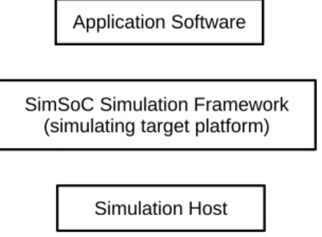
The idea is to run the exact application binary software on the simulation framework as described in diagram below.
Figure 1: SimSoC execution diagram
The target platform is simulated on a host machine. For example, the ST Spear600 platform is simulated on a PC. One must simulate the instruction set of the target, the state and behavior of the processor. For example, a comparison instruction usually positions a condition code that must be emulated in the machine state, and the simulation must simulate that.
The target instruction all together form the instruction set. The instruction set is simulated by the Instruction Set Simulator or ISS. An ISS is instruction accurate when the state of the CPU is known between each instruction; an instruction accurate ISS can abstract the micro-architecture of the CPU (e.g. pipelines).
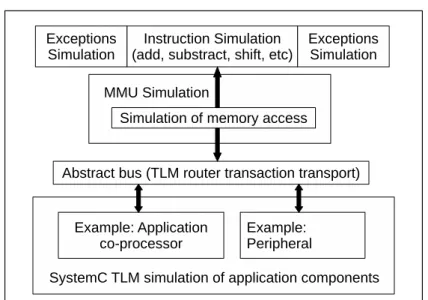
SimSoC consists of two parts: the simulation of some hardware components in System-C/TLM, and the simulation of other components, in particular off-the-shelf processors, as illus-trated in diagram 2.
The simulator of a particular processor is named a CPU simulator. A machine simulation therefore includes three parts: simulation of each individual instruction, simulation of state and behavior, simulation of communication with devices.
To simulate accurately some processors it may be necessary to also simulate one or more specific co-processors.
Communication with peripheral devices, or peripherals, must be simulated too. SimSoC assumes that all simulated processors are carrying I/O’s through memory-mapped I/O’s, that is, communication with devices is carried through load-stores on specific memory addresses, also called I/O ports.
To simulate state, a data structure is defined called the state. The environment contains in particular the simulated CPU registers, both general purpose registers and state registers of the
Figure 2: SimSoC architecture
machine. At any time, it must reflect accurately the state of the simulated CPU.
Processors execute instructions that are referred to by the register of Program Counter (PC). Most processors nowadays use a Memory Management Unit (MMU). In particular, the mech-anism to translate a virtual address into a physical address is usually handled by the MMU. The MMU must be simulated; the simulation includes the behavior of virtual memory management.
3.3
Overview
SimSoC is activated with a command line that takes a number of arguments, and possibly a configuration file. These arguments are given to the SystemC elaboration code, which build the architecture of target platform.
Each hardware component of the target platform is simulated by a SystemC module. In particular, the CPU simulator with its MMU is included in a SystemC module. The MMU generates SystemC-TLM transactions to the other devices trough its initiator TLM port. The CPU simulator implements a function to receive interrupts, which are forwarded by the interrupt controller (IRQC).
Target memory is simulated with host memory. Memory is implemented as a TLM target module. It can receive transactions from any module in the system but it also provides a direct access to memory for the CPU simulator. At start-up time, a large memory space is allocated on the host, equal to the size of the simulated memory. Therefore, assuming the beginning address of that space on the host is “a”, then the translation of physical address “b” of the target is simply “a+b” on the host. Also, It is assumed that virtual memory is paged.
4
Modeling Frameworks
In this section some modeling frameworks are introduced. The tool chain mainly uses modeling frameworks related with Eclipse that will be introduced in detail.
4.1
Eclipse Modeling Framework
Eclipse is an Integrated Development Environment (IDE) which has been widely used for var-ious development for more than 10 years. It was initially designed for Java development, and because of its plug-in system, its function has been expanded into a full-featured IDE for other programming languages. In addition, Eclipse can be used for building models by using Eclipse Modeling Framework (EMF).
By the definition from its official website http://www.eclipse.org/emf, “The EMF project is a modeling framework and code generation facility for building tools and other applications based on a structured data model. From a model specification described in XMI, EMF provides tools and runtime support to produce a set of Java classes for the model, along with a set of adapter classes that enable viewing and command-based editing of the model, and a basic editor.” In addition to be a complement modeling framework, EMF has also been used as a stable standard by many other technologies in the Eclipse world.
The core EMF framework consists of three fundamental parts:
• EMF Core: The core of EMF framework includes a meta model (Ecore), which can be considered as a UML dialect, for describing models, with a runtime which has a set of class system and support for reflective API of EMF objects and some other features.
• EMF Editor: A programmable framework which allows developers to program on the behavior of modeling editor and customize some features such as content and label provider etc.
• EMF Code Generator: The EMF code generation facility is able to generate everything needed to build a complete editor for EMF model. It includes a GUI which can be used to specify generation options and invoke generators.
Apart from being used directly as a modeling tool, Ecore file format introduced by EMF is also used by other modeling frameworks to hold information. Ecore becomes a generally used exchangeable file format between frameworks built upon Eclipse environment.
4.2
Textual Modeling Framework
Textual Modeling Framework (TMF, also known as Xtext) is both a framework and a tool for developing Domain Specific Language (DSL). After defining the grammar with a meta language, Xtext will generate lots of commodities for the DSL such as a parser, a syntax checking editor, and utilities to facilitate type checking and code generation from the DSL. Xtext uses EMF to construct an Abstract Syntax Tree (AST) and generate a fully featured Eclipse syntax directed text editor, that may have many features like text coloring, error checking, formatting, refactoring and so on. Reusable Java classes are generated by Xtext and DSL developers may manually write code to provide additional functions operating on the generated structures. Here lists some Xtext features mainly used by the platform:
• The AST. The parser automatically generated from the grammar (using the ANTLR tech-nology from http://www.antlr.org/) constructs an AST, the nodes of which are customiz-able in the grammar definition. By default, it constructs an AST that directly reflects the concrete syntax, but one may specify otherwise in the grammar.
• Validator. The Xtext framework contains a validator which can be customized to check if the DSL instances contain any error. The validator can be set to be triggered automatically after the user finishes typing, or when the user saves the file, or by manually clicking. The
reflective feature of Xtext framework makes it possible for the validator to access the current context of each grammar element to be checked. When errors are detected, the validator may provide error marks and quick fixes programmed inside the validator. Also, some validation code can be specified to be called only to check some sub-tree of the AST, using the “@Check” annotation mechanism.
• Generator. when the user saves a DSL file, the Xtext framework calls the validators and if no errors are reported, it then calls the generator The generator can be used to generate code from the DSL, or whatever function is needed after the user saves the DSL file. Inside the generator, it is possible to access the AST. After the generator finishes execution, Xtext restarts its current loop.
• IDE support. The Xtext framework offers support for several different IDEs to edit the DSL instances. For Eclipse, DSL developers can provide many nice features like content consist, labeling, outline etc. These features can be very helpful when the DSL is complex and the user may get code template or other convenience. For example, when the user presses ctrl + space, Xtext shows a pop-up window to let the user select from possible completions. This feature can be programmed and provide many customized completions. The Xtext framework also has some other facilities such as cross reference and scope, unit tests. It simplifies the development of DSL and makes it easier to integrate with other facilities.
4.3
Xtend the Language
In the Xtext framework, the programming language can be either Java or Xtend. Xtend is a statically-typed programming language based on top of Java. In fact, the Xtext framework will parse Xtend codes and generate corresponding Java codes from Xtend. The grammar of Xtend looks similar to Java, with less redundant and some helpful concepts which may help speedup the development:
• Operator overloading. Like C++, Xtend make it possible to overload operators for any type by implementing the right method signature.
• Type inference. Xtend has a strong type inference system. Type of variables or methods can be automatically inferred according to the context. So that developers do not have to specify the type explicitly.
• Multiple dispatch. It is also called polymorphic method invocation, meaning that methods can be invoked according to the inheritance of method arguments. In Java, polymorphic only works with objects which invoke methods instead of arguments. Xtend supports keyword dispatch which will add multiple dispatch support to a trivial function. The translated Java is actually a series of if-else clauses with instanceof checking.
• Powerful switch expressions. switch expression in Xtend not only works with trivial value types like Java, but also works with complex data types such as String and other abstract data types. Xtend uses equals method to compare the values. Instead and in addition to case guard, Xtend supports type guards which can check the type of switch argument. Note that a type guard and normal predicate can be used together which will be satisfied when both guards match.
• Expressions instead of statements. Xtend has no concept for statements because everything in Xtend is an expression so that can return a value. Together with type inference, this would save a lot of time.
Xtend adds some new concepts from other languages together with some syntax sugar. In Xtext framework, it is somehow equivalent to use Xtend versus Java. But Xtend code is usually more readable and expressive compared with original Java code.
5
Project Goal
When a user is designing a hardware component or developing embedded software, it is usually helpful to test the product on a simulator first. In both cases, the system usually has some constraints to satisfy. If the developers wants to find the bugs inside the system where constraints are violated, they have to investigate the actual execution of the hardware/software system in order to analyze it. A widely used method consist in recording data during execution of simulation. The recorded information is called the trace.
Running many executions of a VP simulator with different input conditions, it generates a lot of traces that record the various simulation sessions. The traces are usually dumped into trace files, and the traditional way to analyze errors is to look into the trace file and study what has happened during the simulation sessions. For example, if users are running software upon SimSoC and want to tell if there is any violated constraint, they have to dig into the trace file and compare it with the correct behavior. There are two major problems during manual analysis:
1. It is hard to extract useful information from a huge trace file. A trace file generated by a VP simulator often contains very detailed information about the system, including some internal states, and the trace file can reach gigabytes of data, which is too huge to handle manually.
2. It is difficult to reason about the detailed traces. Because the trace often contain raw binary data and not symbolic information, it may not be obvious to reason about a long chain of causality events that eventually lead to the failure. The too low level detailed trace information makes it hard to reason at abstract level.
In order to simplify the complexity during trace analysis, we propose a platform that makes it possible to reason at a higher level of abstraction, and does automated verification of the trace to find violated requirement. Our platform relies on the concept of logical clocks as proposed in the Constrained Clock Specification Language (CCSL). Our platform is ultimately verifying properties expressed as logical clocks formulas that must be satisfied, the logical clocks being extracted from the trace files.
In a first step, we want to reduce the size of traces generated during one execution of simu-lation and express the trace streams at a higher level of abstraction. The platform must provide a way for modeling the trace, filter out the low-level details, and possibly synthesize complex data structures from the raw trace into a single logical clock tick (reduce many bytes of data to a few). We provide to that end a concept of event model, derived from a meta-model, which can be mapped in an automated way to the abstract level of logical clocks.
Next, the platform provides a specification language to express the property constraints of the hardware/software design. The language should be carefully designed to be both simple and powerful:
1. For engineers, it should be simple enough to learn so that engineers can use it to express the system properties very quickly. We do not want to set as a pre-requisite for the engineers to be experts either in linear temporal logic, or in CCSL algebra.
2. Considering the function considered, it should be powerful enough to cover most popular cases and provides possibility to express some non-common but useful situation. Note that, because trace files are by construction finite, we do not need to reason on infinite traces... 3. For future extension, it should be flexible enough to allow future development of the
lan-guage to add more expressions.
Finally, the platform should have a verifier which takes the property specifications and traces generated by one execution, and verify if any property is violated during the execution. The verification should be automatically done with an easy-to-use user interface and gives analysis result in a readable way. Also, one should be able to invoke the verifier in two modes: offline mode in which the verifier takes a trace file and analyzes it; runtime mode in which the verifier takes the traces generated by simulator on the fly. If any error is detected during the verification, the platform should provide a GDB-like debugger which makes it possible to analyze the trace piece by piece to find out the root of problem.
In addition, some other features are also interesting for the developers. In real embedded hardware/software applications, there are most often different phases/stages during an execution. The platform should support the notion of scope so that some properties only take effect in some specific scopes. The scopes should be able to overlap and be nested. Different scopes do not affect each other, and are independent from trace events.
Another aspect is that recompiling a simulator can be tedious, and sometimes impossible if all of the source code is not available. In order to facilitate usage of our property checker, we have added the constraint that modifying the trace generation for checking new properties should be fully dynamic and should not require recompiling the simulator.
In conclusion, the goal of this project is to provide a platform that let users to define trace event, how these events map to logical clocks and scopes, what are the properties that should be verified, and then automatically analyze and verify the traces generated by the simulator on the fly, and possibly debug the traces if any errors are detected; all of this without having to recompile the simulator when checking different properties based on difference clock specification.
6
Related Works
As mentioned above, the goal of this project is to overcome the difficulty of analyzing simulation traces and verifying the properties. Trace analysis has been a topic for some time in the simulation community, so that many people have worked on it and gave some approaches.
Several languages in the literature allow to express temporal properties. Linear Temporal Logic (LTL) [2] abstracts the system behavior as an infinite sequence of states and establishes either properties of invariance of eventuality. All the properties are expressed relative to the steps of execution, using model temporal operators, and not relative to an external clock. There are also some other formal specification language designed for trace verification such as Com-putational Tree Logic (CTL) [3] and Graphic Interval Logic (GIL) [4]. However, all of these specification languages cannot be used to specify real-time properties because none of them sup-port quantitative reasoning about time. Later, several efforts such as Metric Temporal Logic (MTL) have been made to provide real-time extensions for LTL.
However, languages like LTL and its extensions can be very complex in practical use. The users must know well about the formal theory behind the language to use it well. In order to provide a higher level of abstraction which can be used to express constraints in real-time systems, Balarin and al. [5] introduced a new specification language, named Logic Of Constraints (LOC). Later on, Chen [6] has used LOC as theoretical basis and built an algorithm to generate model
checker in C++ to verify the properties specified in LOC on simulation trace. After using LOC to express annotations including sequential index, time and causes relation, the generated checker can verify properties such as rate, latency, jitter, etc.
As SystemC is widely used by the embedded system community, the specific Value Change Dump (VCD) trace format has been defined for tracing and many commercial or non-commercial tools have been developed for analyzing it. The C-based Unified Logging and Tracing (CULT) [7] system has introduced a flexible trace generation framework for C-based designs of embedded hardware/software systems. The framework is highly configurable and scalable, but there is no associated tool to analyze the traces produced. A SystemC analyzer like [8] can be used to specifically verify temporal properties holding in the SystemC processes, but it requires access to the SystemC modules and cannot check information produced by embedded software running over the simulated hardware.
The COSITA tool [9] makes it possible to analyze traces resulting from co-simulation between SystemC and Matlab models for automotive applications. The tool uses VCD to dump the execution trace of their platform and feed the trace to both simulator and emulator to compare the difference, but there is no property specification language defined from the paper. This paper [10] is used to verify properties in traces of packets in network simulation, using the Monitoring And Checking (MAC) framework [11]. It is based on a logic for events and conditions, which allows to consider instances of events by means of counters, similar to LOC.
Referring to property specification language, Dwyer et al published in 1999 a classic paper [12] which did a survey from many sources and developed a pattern system. Their pattern system covers most popular situations. Based on their research, this paper [13] builds a new pattern system containing some real-time extension. Also, they studied many formal specification lan-guages and provides an English-like grammar which can be rather convenient. However, their paper does not refer to the implementation, thus there is no information of how to really apply their pattern system to the real simulators or on the real simulation traces.
Regarding the tool aspect, the Open Trace Format 2 [14] provides a flexible trace format that inspired our mapping work.
7
System Design
7.1
Architecture
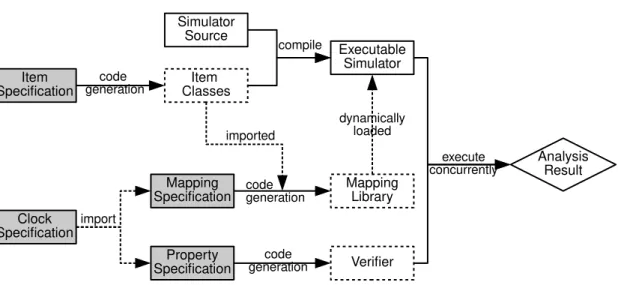
The global architecture of this project is decomposed as shown in figure 3. One complete execu-tion instance of TRAP contains four independent steps:
1. First the simulator runs and generates well-formed trace items, which are data structures defined inside trace item model.
2. In the second step, the trace items are transformed into corresponding clock ticks according to the mapping rules that is expressed by a pre-defined DSL. After that, simulator is able to generate stream of logical clock ticks in some fixed format.
3. In the third step, the trace stream is fed into the verifier and system properties are expressed by another pre-defined DSL.
4. Finally the verifier analyzes the stream of clock ticks and checks if properties are satisfied and gives the analysis result.
In the figure 3, the gray rectangles represent the input of the platform that will be im-plemented by the end user. All the DSL languages for specifications are defined using Xtext
Figure 3: Platform architecture
framework. The dashed rectangles represents C++ components that will be generated according to the input. During the development of TRAP, SimSoC is used as the simulation back-end. However SimSoC and TRAP are loosely coupled and by definition, TRAP can be integrated with any simulator back-end as long as the simulator uses interface provided by TRAP to generate traces. The interface and requirements will be introduced in detail in section 14.
7.2
Main Components
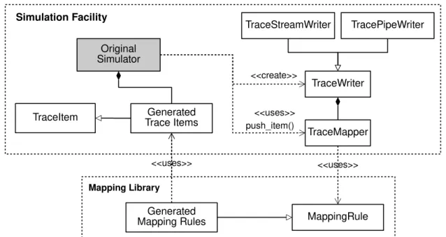
Given any simulation platform, there must be a corresponding specification describing infor-mation structures. It represents what kind of inforinfor-mation it can provide to its simulator user. TRAP defines a DSL for this purpose named Trace Item Specification Language (TISL). This language defines all the trace items and corresponding data types used in next process. Each trace item stores a basic information structure that can be a hardware interrupt, a designed event or a plain information block.TRAP generates C++ code according to the specification. The generated code together with some previously written code can be integrated into simulator and compiled together to get an new executable simulator. Inside this new simulator, the traces are generated via interface provided by TRAP will generate a stream of trace items instead of raw state changes.
Runtime verification is based on the logical clock notion from Clock Constraint Specification Language (CCSL) [15]. In this theory, the basic notion of trace is a infinite sequence of clock ticks. TRAP takes the notion logical clock to represent a basic “event” during the execution. Logical clocks in TRAP are then used to describe system properties and they are defined in the clock specification DSL named Logical Clock Specification Language (LCSL). Since TRAP analyzes the trace generated during one execution of simulator, it does not deal with the infinite traces and this is a big difference between TRAP and CCSL based tools.
After trace items and logical clocks are defined, the next step is to provide mapping rules telling how patterns of trace items are transformed into logical clocks. This step is inspired by Open Trace Format 2 [14] and it converts a trace item stream into a stream of logical clock ticks. Mapping rules are defined via Simulation Trace Mapping Language (STML). TRAP takes the DSL instance and generates code consisting dynamic library for mapping. This library will be loaded dynamically by executable simulator to do the transformation. Since dynamic
library and simulator works through an interface, modification of STML instance does not require recompilation of simulator. After this step, simulator is ready to run and generate clock tick stream.
Since the goal of this project is to provide runtime trace analysis, the most important part is to express system properties. Another pre-defined DSL named Trace Property Specification Language (TPSL) is used to specify specify system properties. TRAP takes DSL instance and generates C++ code that will compose with verifier and verify the traces for corresponding properties. Each time the properties are changed, the verifier must be re-compiled with newly generated code.
Verifier contains two parts: 1) the basic library providing template-like facilities; 2) code generated from TPSL that uses the library. Verifier can be invoked via command line interface. It can work in three modes:
1. Offline mode. Verifier takes a trace file generated by simulator and analyze it line by line. If there are any properties that are not satisfied, it gives an error. After all, it gives a summary of all the properties according to the trace file.
2. Pipe mode. Verifier analyzes the trace stream just like offline mode, except that under this mode, it runs simultaneously with simulator and reads clock ticks from a named pipe. 3. Debug mode. Verifier takes a trace file and waits for the user input via a command line
interface. It provides tick-by-tick analysis and so on according to the user command. After this step, the analysis result is given and one cycle of execution is finished.
7.3
Summary
In summary, TRAP is used as follows from a user’s perspective:
1. Basic trace items and logical clocks are defined using TISL and LCSL respectively and the simulator is compiled together with code generated in this step.
2. Mapping rules are provided using STML and a dynamic library are compiled using code generated in this step.
3. System properties are specified using TPSL, verifier is compiled with generated code. 4. Simulator loads the mapping library and generates trace stream, and verifier takes the
trace and analyze it.
In the chain of TRAP, simulator, mapping library and verifier are weakly connected with each other so that modification of one piece does not affect the others. This flexible way makes it possible for engineers to work in parallel and then merge their works. In the rest of this section, these components of this platform will be introduced in detail.
8
Trace Item Specification Language (TISL)
8.1
Overview
TISL contains every necessary information for trace emission and is closely related to simulation back-end, thus by definition should be provided by simulator developers. Grammar of TISL is similar to C++ declarations, specifying alias of data types, declaration of enumerations and trace
items. Each item is an abstraction of a series of internal state changes or information collections of simulator. These specifications are transformed into C++ typedef, enum and class using Xtext generator. As mentioned above, code generated by TISL generator should be put into imports/ directory inside given C++ code.
All the specification language make use of Xtext IDE support and provide content assistant at the right time. For example, <target-directory> introduced in next sub-section can be completed with content assistant triggered by ctrl+space and let user choose desired directory in a pop-up window.
8.2
Grammar
The BNF-like grammar of TISL can be expressed as following:
⟨item-specification⟩ ::= ‘generate’ ⟨target-directory⟩ ⟨definition⟩* ⟨definition⟩ ::= ⟨type-definition⟩
| ⟨enum-definition⟩ | ⟨item-definition⟩
⟨type-definition⟩ ::= ‘type’ ⟨type-name⟩ ⟨real-type⟩ ⟨real-type⟩ ::= ⟨built-in-type⟩ | ⟨custom-type-name⟩ ⟨built-in-type⟩ ::= ‘int’ | ‘int8’ | ‘int16’ | ‘int32’ | ‘int64’ | ‘uint’ | ‘uint8’ | ‘uint16’ | ‘uint32’ | ‘uint64’ | ‘bool’ | ‘float’ | ‘double’
⟨enum-definition⟩ ::= ‘enum’ ⟨enum-name⟩
‘{’⟨enum-literal⟩ (‘,’ ⟨enum-literal⟩)* ‘}’
⟨item-definition⟩ ::= ‘item’ ⟨item-name⟩ (‘extend’ ⟨item-name⟩)?
‘{’⟨attribute-definition⟩* ‘}’
⟨attribute-definition⟩ ::= ⟨type-name⟩ ⟨attribute-name⟩ (‘[’ ⟨array-size⟩ ‘]’)?
TISL by default supports some built-in data types, which maps to C++ built-in simple types. Other than that, some custom data types can also be defined by using keyword type and providing information of custom type name and string of real type. The built-in types and custom types can then be used in item declarations.
• <target-directory> tells TRAP where to put the generated C++ code. It must be an existing directory pointing to the imports/ sub-directory in the pre-written code.
• <type-definition> declares a C++ type and its alias. <real-type> is a built-in type or a string representing a valid C++ type while <type-name> is an alias that can be used in other specifications.
• <enum-definition> is translated into C++ enum directly, so all the <enum-literal> will stay in the same namespace. Thus, each single <enum-literal> must be unique.
• <item-definition> contains a list of attributes. <attribute-definition> is a pair consisting of a built-in type name or <type-name> defined previously and its own name <attribute-name>. Also an attribute can be an array of elements and the size is specified by <array-size>.
8.3
Example
Suppose there is a chip designed for controlling train system and there is a simulator that simulates this hardware. During the door is closing, the light above the door will blink to warn passengers. Suppose the light has different colors and may blink with different rate for some time. Then the information item of “the light of some color blinks for some time with rate” may be abstracted as following:
type IntType " u i n t 3 2 _ t " enum C o l o r {
RED, YELLOW, GREEN } item L i g h t B l i n k { C o l o r c o l o r ; I n t r a t e ; I n t d u r a t i o n ; }
When the program built upon the simulator needs to serialize the information of light blinking, it should create an instance of generated C++ class defined by “item LightBlink”, then set value of its attributes and call the TRAP emission interface.
9
Logical Clock Specification Language (LCSL)
9.1
Overview
As a notion taken from CCSL, logical clock is the basic block for expressing system properties. A clock is one kind of basic “event” happening during the abstract time line. Each clock may
tick as many times during the time line. Each clock tick has mainly two attributes: timestamp
and name of the clock. All of the clock ticks share the same physical real time clock, thus the timestamp represents the presence order of ticks in the trace stream.
In TRAP, logical clocks are defined by the clock specification, which provides a higher layer of abstraction than the item specification because it is isolated with the low-level detail of simulator and represents more on logical level. A clock specification defines basic items of behavior of the hardware component or software that will run upon the simulator.
9.2
Grammar
BNF-like grammar of LCSL can be expressed as below:
⟨clock-specification⟩ ::= ‘scope’ ⟨scope⟩* ‘clock’ ⟨clock⟩*
Compared with other languages, grammar LCSL is rather simple. However it is important because scopes and clocks defined inside LCSL will be used by both STML and TPSL. Logical clocks are declared using keyword clock followed by a list of names, and keyword scope declares a list of phases. During the execution of simulator, HW/SW system may have different phases. Inside different phases, there may be different system properties to verify. In TRAP, phase are called scope that is defined in LCSL. Scopes may overlap with each other, so nested scopes can be expressed simply by overlapping two scopes with different ranges.
9.3
Example
Consider the train control system example in TISL section. During its execution, the train may have several phases: speed_up, uniform_motion, slow_down etc. Also, there might be many actions like door_open, door_close, light_blink_rapidly and light_blink_slowly. It can be declared using LCSL shown below:
scope speed_up uniform_motion slow_down
clock t r a i n _ s t a r t t r a i n _ s t o p door_open d o o r _ c l o s e l i g h t _ b l i n k
10
Simulation Trace Mapping Language (STML)
10.1
Overview
Since item specification and clock specification provides two different layer of abstraction, there must be a specification defining how to convert trace items into clock ticks, i.e. a mapping language. In this platform, STML builds the bridge between items and ticks. This mapping language defines how the items are mapped into clocks in a pattern matching manner. It takes as input two parameters, on one hand the TISL instance file, on the other hand LCSL instance. STML takes another parameter as output, which defines the place where the platform put the generated C++ codes.
Since logical clocks represents system events in a larger scale, several trace items may be mapped into single logical clock. Thus the timestamp may be scaled so that trace items of different timestamp can map to one tick. Here a notion of period is introduced to describe the maximum interval of trace items timestamp (i.e. real system clock) that will be considered as one timestamp in logical clock side. All the timestamp within one period is considered to be simultaneous while mapping. This design reflects the fact that trace item models lower level properties than logical clocks.
An STML instance consists of a header importing the item specification and the clock speci-fication, then global variable definitions, then a set of rules, each one introduced by the keyword for followed by a item name defined inside TISL instance that defines the rule for that trace item. For each final item (i.e. not inherited by other items) in the trace model, there must be a corresponding mapping rule defined for it inside mapping specification, so that the mapping is guaranteed to be fully defined.
For each matched pattern, the mapping consists in transformation the input items into one of the three possibilities:
• simply ignore the pattern because it is irrelevant to the properties considered in this anal-ysis. It is introduced by keyword ignore meaning no output clock ticks in this case. • enter or leave a scope defined in imported LCSL instance with keyword enter or leave. • emit a list of clock ticks introduced by keyword emit.
The language also has constructions related to the trace model. Given the input item speci-fication, it makes it possible to:
• specifify conditional action, with a boolean condition and two branches. The condition must bear on the values of the attribute of items, or on the global variables. Each branch can be a basic action, or another nested conditional action.
• check for a sequence of items that finally construct a pattern. This sequence of items is specified using a construction similar to switch instruction in C++ programming language, introduced by keyword when followed by candidate case, with a mandatory else clause in case the sequences of items specified are not matched. This construction builds a pattern tree used by the pattern matching algorithm described in section 14.
• assign some attribute value of an item to a global variable. This feature makes it possible to considerably reduce trace file sizes. Indeed in many cases the trace items contain state information that is duplicated over and over again in the trace, whereas the verification is only interested in state changes. Global variables in the language make it possible to only emit clock ticks when some particular global values have changed, and the conditional makes it possible to quantify that change. For example, it is possible to express the case “emit a clock tick if the train speed has increased by more than 10% compared to last time considered”.
By defining the mapping rule for each trace item, any trace items stream can be mapped into clock ticks to generate a new trace. Since the mapping process may ignore some data, or reduce repeated state to state changes only, and reduce multiple items into a single clock tick, the size of trace stream can be remarkably reduced when studying a given set of properties. After mapping, the engineer is able to focus on the clocks and scopes that provide much higher abstraction for reasoning on properties.
10.2
Grammar
BNF-like grammar of STML can be expressed as follows:
⟨mapping-specification⟩ ::= ‘mapping’ ⟨item-specication-file⟩
‘to’⟨clock-specification-file⟩ ‘generates’⟨target-directory⟩ ‘from’⟨source-directory⟩ ‘;’
⟨global-variable-declaration⟩* ⟨rule⟩+
⟨global-variable-declaration⟩ ::= ⟨type⟩ ⟨global-variable⟩
‘=’⟨global-variable-initial-value⟩
⟨global-variable-initial-value⟩ ::= ⟨constant⟩
⟨global-variable-initializer⟩ ::= ⟨item⟩ ‘.’ ⟨attribute⟩ ⟨rule⟩ ::= ‘for’ ⟨item⟩ ⟨variable⟩ ‘{’ ⟨statement⟩ ‘}’ ⟨statement⟩ ::= ⟨simple-stmt⟩
| ⟨sequence⟩
⟨simple-stmt⟩ ::= ‘ignore’ ⟨global-variable-update⟩*
| ⟨emission⟩ ⟨global-variable-update⟩* | ⟨conditional-stmt⟩
⟨global-variable-update⟩ ::= ‘update’ ⟨global-variable⟩
‘=’⟨variable⟩ ‘.’ ⟨attribute⟩
⟨emission⟩ ::= ‘emit’ ⟨clock⟩
| ‘enter’⟨scope⟩ | ‘leave’⟨scope⟩
⟨conditional-stmt⟩ ::= ‘if’ ‘(’ ⟨boolean-expr⟩ ‘)’ ‘{’ ⟨simple-stmt⟩ ‘}’
‘else’ ‘{’⟨simple-stmt⟩ ‘}’
⟨boolean-expr⟩ ::= ⟨boolean-expr⟩ ‘||’ ⟨boolean-expr⟩
| ⟨boolean-expr⟩ ‘&&’ ⟨boolean-expr⟩ | ‘(’⟨boolean-expr⟩ ‘)’
| ‘!’⟨boolean-expr⟩ | ⟨comparison⟩
⟨comparison⟩ ::= ⟨arithmetic-expr⟩ ⟨compare-operator⟩ ⟨arithmetic-expr⟩ ⟨arithmetic-expr⟩ ::= ⟨arithmetic-expr⟩ ⟨arithmetic-operator⟩ ⟨arithmetic-expr⟩
| ‘-’⟨arithmetic-expr⟩ | ‘~’⟨arithmetic-expr⟩ | ‘(’⟨arithmetic-expr⟩ ‘)’ | ⟨primary⟩ ⟨compare-operator⟩ ::= ‘<’ | ‘<=’ | ‘==’ | ‘!=’ | ‘>=’ | ‘>’ ⟨arithmetic-operator⟩ ::= ‘+’ | ‘-’ | ‘*’ | ‘/’ | ‘%’ | ‘&’ | ‘|’ | ‘^’
| ‘«’ | ‘»’ ⟨primary⟩ ::= ⟨integer-constant⟩ | ⟨boolean-constant⟩ | ⟨enum-literal⟩ | ⟨global-variable⟩ | ⟨variable⟩ ‘.’ ⟨attribute⟩
⟨sequence⟩ ::= ‘when’ ⟨pattern⟩* ‘else’ ⟨simple-stmt⟩ ⟨pattern⟩ ::= ‘either’ ⟨item⟩ ⟨variable⟩ ‘:’ ⟨statement⟩
As shown in the grammar, global variables are introduced by
<global-variable-declaration> above the definition of mapping rules. Global variables can be initialized by a constant, or a list of initializers. Each initializer consists of a pair of trace item and its attribute. During the simulation, global variables will be initialized by the first trace item belonging to the initializer list when it shows up. This only work for the first time. Later, the update of global variables are specified by <global-variable-update> via assigning attribute value to the global variable. Update field is designed to appear after <emission> or <ignore> because global variables follows read-then-update pattern.
The element <pattern> in the grammar reflects the concept of pattern matching mentioned above. It can be nested to build several patterns. A pattern is a tree of trace items, with its root being the start point for matching. Any path of the tree (i.e. a sequence of items) represents a case that once matched, <simple-stmt> will be taken into account. This filters out patterns that is not interesting for analysis.
Also inside STML, <variable> has its visible scope. Notion scope here is different from LCSL, here it denotes the life time of a variable. Local variables inside STML are introduced by <rule> or <pattern>, and referred to by their identifier inside <expressions>. A local variable introduced by any grammar element can be seen inside the children element, but not sibling elements.
STML supports various ways to express arithmetic expressions and values. All the arithmetic operators in C++ programming languages is supported and the operator precedence is exactly the same as C++. Also, apart from decimal constants, different representation of integer con-stants including hex, octal, binary are supported by specifying 0x, 0, 0b in front of the number respectively.
Some other tokens are described below:
• <item-specification-file> and <clock-specification-file> represents location of instance files of TISL and LCSL respectively.
• <target-directory> indicates the location to put generated code.
• <source-directory> is the directory of code prepared by TRAP including C++ classes generated by TISL.
• <item> is id of trace item defined inside event specification.
• <clock> and <scope> are valid names of clocks and scopes declared in the clock specifica-tion.
10.3
IDE Support
TRAP contains a validator that will detect any errors on-the-fly and give error marks when the user stops editing. Any mistake in the events, clocks, scopes and attributes, will be spotted. Also, the platform is loading the event model and clock specification right after the user defines them. If the imported models cannot be loaded properly, an error message will be given to the user about it. Every time the user changes the location of the model, the platform will reload it automatically.
An important feature is type checking. For example, comparison can only happen when left and right operands have the same type, and operands of boolean operators must both return boolean values. In STML, when an expression is taken into account, type checking works as follows:
• If both operands (sometimes one operand) are defined with built-in data types introduced in TISL section, type checking is triggered. In this case, operands must have the same data type as operator requires, otherwise an error is signaled. If two data types are in the same category but have different types, for example one int16 variable is compared with one int32 variable, a warning instead of an error is given.
• If any one operand has a custom type, type checking mechanism works in another way. Since a custom type is defined with string, STML validator does not know what the real type is. In this case, the type string is compared and if they do not match, a warning is given.
STML editor also contains some other features that makes development of instances easier: • Event template. After the user specifies the imported event model, the platform will parse
the model and extract all the final events, so the platform will provide a list of final events defined in event specification with an “ignore” as the default behavior.
• Name completion. The name of events, clocks and scopes can be automatically completed according to the event model and clock model.
• Attribute completion. Since STML allows comparison between values inside boolean con-ditions, it is possible to access the attributes of events. After typing ‘.’, the code assistant will give a list of valid attributes of that event.
• Pop-up window for directory selection. Same as TISL.
10.4
Example
Consider the blinking light inside train controlling system. Suppose if the light blinks in green or yellow color, it is ignored; otherwise it is in red color, light_blink_rapidly and light_blink_-slowly will be emitted according to the rate. This example can be expressed by following:
f o r L i g h t B l i n k b { i f ( b . c o l o r == RED) { i f ( b . r a t e <= 0 . 5 ) { e m i t l i g h t _ b l i n k _ r a p i d l y } e l s e { e m i t l i g h t _ b l i n k _ s l o w l y }
} e l s e {
i g n o r e }
}
11
Trace Property Specification Language (TPSL)
11.1
Overview
After mapping, the original trace has been transformed into clock ticks. Now the clocks and scopes defined inside clock specification can be used to specify the properties of the HW/SW system user wants to verify. Considering the fact that most commonly used patterns are causality, universality and absence [13], pattern system in TRAP was built covering these ones and others commonly used in the embedded system development. In order to make it easy for engineers, TPSL was built as an English-like language to express the patterns with the Xtext framework. This makes it possible for user to define properties without needing to know CCSL algebra behind TPSL.
The TPSL specification takes the clock specification as input, imports all the clocks and scopes defined inside it, and at last generates corresponding code for verifier. A valid TPSL file consists of three parts:
1. Constant declaration. Constants are defined at the beginning of TPSL files and then used inside the rules. Currently only integers with arithmetic operations including addition, subtraction, multiplication and division are supported.
2. Clock declaration. To make it clear, clocks defined inside clock specification are called basic
clocks, while those defined in this section are called virtual clocks. Basic clocks is acquired
after mapping and virtual clocks is a composition of other clocks using logical clock algebra operations like union, intersection etc. Both base clocks and virtual clocks can be used by the rules defined in the same TPSL file.
3. Rule declaration. This section consists of a list of rules that each one expresses one property of the system and will be verified by TRAP verifier. Each rule will be checked inside its own scope defined inside clock specification. If a rule contains more than one scope, then the intersection of scopes are taken into account in such cases.
Each rule can be one of the supported patterns. Some patterns are taken as a subset from CCSL and then extended to provide more functionality, while some others are commonly known in embedded HW/SW development. Given a TPSL file, TRAP generates C++ code consisting the verifier by compiling them together. Each verifier executable file is gain from a specific TPSL instance file.
11.2
Grammar
BNF-like grammar of TPSL is shown as follows:
⟨property-specification⟩ ::= ‘import’ ⟨clock-specification⟩
‘generates’⟨target-directory⟩
⟨constant-declaration⟩ ::= ‘define’ ⟨constant-assignment⟩
(‘,’⟨constant-assignment⟩)*
⟨constant-assignment⟩ ::= ⟨constant-variable⟩ ‘=’ ⟨arithmetic-expression⟩ ⟨arithmetic-expression⟩ ::= ⟨constant⟩ ⟨arithmetic-operator⟩ ⟨constant⟩
| ‘(’⟨arithmetic-expression⟩ ‘)’ ⟨constant⟩ ::= ⟨constant-variable⟩ | ⟨constant-value⟩ ⟨arithmetic-operator⟩ ::= ‘+’ | ‘-’ | ‘*’ | ‘/’
⟨clock-declaration⟩ ::= ‘clock’ ⟨clock-assignment⟩ (‘,’ ⟨clock-assignment⟩)* ⟨clock-assignment⟩ ::= ⟨variable⟩ ‘=’ ⟨clock-expression⟩
⟨clock-expression⟩ ::= ⟨clock-union⟩
| ⟨clock-sub⟩ | ⟨clock-intersect⟩
⟨clock-union⟩ ::= ⟨clock-union⟩ ‘union’ ⟨clock⟩
| ⟨clock⟩
⟨clock-sub⟩ ::= ⟨clock⟩ ‘by’ ⟨constant⟩
⟨clock-intersect⟩ ::= ⟨clock-intersect⟩ ‘intersect’ ⟨clock⟩
| ⟨clock⟩
⟨rule-declaration⟩ ::= ⟨scope-declaration⟩ ⟨rule⟩ ⟨scope-declaration⟩ ::= ⟨global-scope⟩
| ⟨inside-scope⟩ | ⟨outside-scope⟩
⟨global-scope⟩ ::= ‘always’
⟨inside-scope⟩ ::= ‘inside’ ⟨scope⟩ ⟨outside-scope⟩ ::= ‘outside’ ⟨scope⟩ ⟨rule⟩ ::= ⟨alternates-rule⟩ | ⟨causes-rule⟩ | ⟨each-causes-rule⟩ | ⟨absent-rule⟩ | ⟨jitter-rule⟩ | ⟨throughput-rule⟩
| ⟨burstiness-rule⟩ | ⟨period-rule⟩
⟨alternates-rule⟩ ::= ⟨clock⟩ ‘alternates’ ⟨clock⟩
⟨causes-rule⟩ ::= ⟨before-expression⟩ ‘causes’ (‘!’)? ⟨clock⟩
(‘unless’⟨unless-statement⟩)? (‘if’⟨if-statement⟩)?
(‘satisfies’⟨satisfies-statement⟩)?
⟨before-expression⟩ ::= ⟨clock-sequence⟩ ‘before’ ⟨before-expression⟩
| ⟨clock-sequence⟩
⟨clock-sequence⟩ ::= ⟨clock⟩ ‘<>’ ⟨clock-sequence⟩
| ⟨clock⟩
⟨unless-statement⟩ ::= ⟨inside-statement⟩ ‘and’ ⟨unless-statement⟩
| ⟨inside-statement⟩
⟨inside-statement⟩ ::= ⟨clock⟩ ‘inside’ ⟨clock⟩ ‘to’ ⟨clock⟩ ⟨if-statement⟩ ::= ⟨clock-count-statement⟩ ‘and’ ⟨if-statement⟩
| ⟨clock-count-statement⟩
⟨clock-count-statement⟩ ::= (‘global’)? ‘count’ ⟨clock⟩ (‘+’ | ‘-’) ⟨clock⟩ ⟨comparator⟩ ⟨constant⟩ ⟨comparator⟩ ::= ‘<’ | ‘<=’ | ‘==’ | ‘!=’ | ‘>=’ | ‘>’
⟨satisfies-statement⟩ ::= ⟨satisfies-statement⟩ ‘and’ ⟨satisfies-statement⟩
| ⟨clock-delay-statement⟩ | ⟨clock-count-statement⟩ | ⟨clock-absent-statement⟩
⟨clock-delay-statement⟩ ::= ‘delay’ ⟨clock-timestamp-expression⟩
‘-’⟨clock-timestamp-expression⟩ ⟨comparator⟩ ⟨constant⟩
⟨clock-timestamp-expression⟩ ::= ⟨clock⟩ ‘.’ (‘first’ | ‘last’)
⟨clock-absent-statement⟩ ::= ⟨clock⟩ ‘absent’ ‘from’ ⟨clock⟩ ‘to’ ⟨clock⟩ ⟨each-causes-rule⟩ ::= ⟨before-expression⟩ ‘each’ ‘causes’ ⟨clock⟩
⟨unless-statement⟩ ⟨satisfies-statement⟩ ⟨absent-rule⟩ ::= ⟨clock-absent-statement⟩
⟨jitter-rule⟩ ::= ‘jitter’ ‘(’
⟨clock⟩ ‘,’ ⟨constant⟩ ‘,’ ⟨constant⟩ ‘,’ ⟨constant⟩
‘)’
⟨throughput-rule⟩ ::= ‘throughput’ ‘(’ ⟨clock⟩ ‘,’ ⟨constant⟩ ‘,’ ⟨constant⟩
‘)’
⟨burstiness-rule⟩ ::= ‘burstiness’ ‘(’
⟨clock⟩ ‘,’ ⟨constant⟩ ‘,’ ⟨constant⟩ ‘,’ ⟨constant⟩
‘)’
⟨period-rule⟩ ::= ‘period ‘(’ ⟨clock⟩ ‘,’ ⟨constant⟩ ‘,’ ⟨constant⟩ ‘)’
Some other concepts are explained below:
• <clock-specification> is the path of clock specification file.
• <target-directory> is the directory where TPSL will put the generated C++ code for verifier.
• <constant-value> is an integer value.
• <clock> is a valid clock defined inside TPSL file, or inside clock specification imported by it.
• <scope> is a valid scope defined in the clock specification imported by TPSL. • <variable> is a valid variable name consisting of characters and underscores.
In TPSL, relationships between two or more clocks can be mainly divided into three categories: clock expressions, clock relations and clock properties.
• A clock expression takes two or more clocks as arguments and defines a new virtual clock from given parameters. In the grammar, virtual clocks are introduced by <clock-declaration> and can be used everywhere <clock> is needed. They tick every time the expression is satisfied, with the timestamp of last input clock who triggered it.
• A clock relation takes two or more clocks as input and defines the constraint of given clock(s). Clock relations are defined by <rule> and they will be verified by the verifier. • A clock property takes exact one clock and expresses the property of it. Similar to clock
relations, they are defined by <rule> and verified by the verifier.
Since TPSL was built as a layer of abstraction upon CCSL, the user may be unaware of the theory behind TPSL. TPSL are designed to be flexible and extendable to provide more possibilities in the future, with consistent behavior among different composition of use cases. In next subsections, clock expressions, relations and properties are explained in detail.
11.3
Clock Expression
Current three kinds of expressions are supported to introduce manually-defined virtual clocks: 1. Subclocking expression specified by <clock-sub>. It takes a clock A and a constant N
as input, and generates a new clock which ticks every N ticks of the input clock A. It is designed to express sub-clocks relying on others.
2. Union expression introduced by <clock-union>. It takes a sequence of clocks concatenated with keyword union. The output clock ticks when any one of input clocks ticks.
3. Intersection expression specified by <clock-intersect>. Similar to <clock-union>, it takes a sequence of clocks as input concatenated with keyword intersect, generating an output clock that ticks when all the input clocks tick simultaneously.
A special case is <before-expression>. Unlike other clock ones, <before-expression> can only be used inside <causes-rule> or
<each-causes-rule>. It can not be used to define a virtual clock, however it introduces an implicit virtual tick used internally by TRAP.
Clock expressions provides more power of abstraction and makes it easier to express compli-cated properties while keeping the syntax neat and clean. TRAP handles nested expressions in a recursive manner, i.e. the expression with highest priority is handled first and acts like one virtual tick to the outside nested expressions. So each expression and relations only cares about its own input clock and ignores the original raw clocks.
11.4
Rule
11.4.1 Overview
In TPSL, each rule defines a system property, thus the verification ability of TRAP is mainly decided by the power of TPSL. A rule consists of two parts: scope declaration and rule body. In TRAP tool, each type of rule is mapped into a specific template of automaton that will be explained in section 14. Every time a rule gets its first input clock inside the corresponding scope, the automaton is activated. During its state transitions, input ticks are fed into the automaton and stored inside its local history. If any error occurs, this automaton fails and is deactivated. If nothing wrong happens this rule is passed for its input and the automaton is reset to the initial state. Scopes and rule body definition will be explained in the following sub-sections.
11.4.2 Rule Scope
As mentioned above, LCSL declares both logical clocks and scopes. In TPSL, each rule has its own scope defined by <scope-declaration>. It indicates the range in which the rule should be verified. For any specific rule, all the clock ticks outside its scope are simply ignored by it. The scope are changed by keyword enter and leave in STML, so the current scopes is changed respectively during the execution. A rule is called active inside its scope. In TPSL the scope of a rule can be defined by composition of three keywords:
1. Keyword always indicates a global scope, also understood as “no specific scope”. Rules inside global scope is active all the time.
2. Keyword inside indicates a scope that the rule is active inside it. 3. Keyword outside indicates a scope that the rule is active outside it.
If more than one scopes are given, the intersection of them will be taken into account. In this case, always actually has no effect. If union of scopes is needed, i.e. “either inside A or inside
B ”, the user has to define another scope logically containing both and use it instead of A or B.
After the scope goes the body of the rule indicating the property of a single clock, or clock relation among several clocks. They will be introduced one by one in the following sub-sections. 11.4.3 Alternates Relation
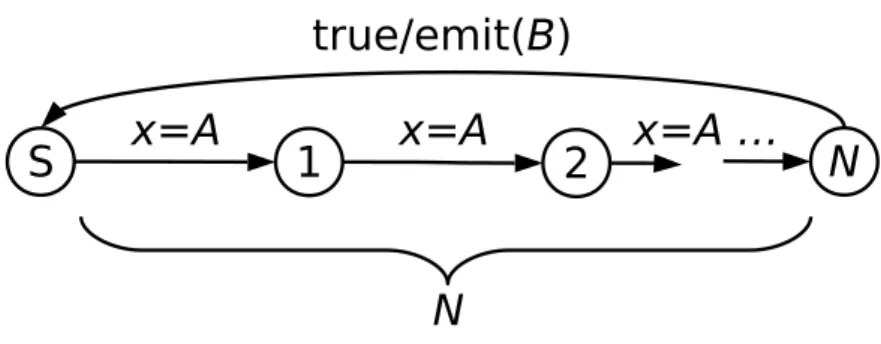
Keyword alternates specifies the relation between exactly two clocks that they tick one after another repeatedly. Neither of the two can tick twice continuously before another one ticks. Also the counts of two clocks must be equal.
11.4.4 Absent Relation
Absence is an important and commonly-used property in embedded HW/SW development. It indicates that some event can never happen between two other events. In TPSL it is defined using keyword absent from with form “target absent from start to end ”, with target, start and
end being valid clock names. By definition, after clock start ticks, if clock target ticks before
another clock end, there is a violation. 11.4.5 Causes Relation
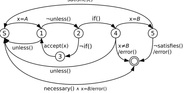
Causality is expressed by keyword causes and is associated with two clocks: trigger and target. It indicates the causality between the two. Note that trigger here can be either a clock or a <before-expression>, given that before expression introduces an implicit virtual clock as mentioned above.
<before-expression> takes one or more <clock-sequence> as input and works in a nested manner. For each “A before B ” part, in which A and B are either clock or <clock-sequence>, any tick of B will trigger the virtual tick if and only ifA ticks at least once before B. If keyword before is replaced with each before, each pair of A followed by B will trigger a virtual tick no matter how far the B is after A. When B here is a <clock-sequence>, it emits a virtual clock tick when all the input clocks have already ticked, without considering the order of ticks.
Causes clause works in two modes depending on the existence of question mark after causes keyword:
• If there is no “!”, <causes-rule> represents a sufficient condition. The basic behavior is that if trigger ticks at some time, there must be a tick of target before the end of simulation, otherwise an error is emitted. Note that it is valid to have several trigger ticks before a single target, or target may tick individually in spite of target.
• If “!” is provided, <causes-rule> becomes both sufficient and necessary. In this case, apart from the normal behavior, for any tick of target, there must be at least one trigger tick before it.
In addition to the basic grammar, three extra control clauses is added to provide more control over the default behavior. They are optional, but if not omitted, they must appear in order. Listed below:
• <unless-statement> starts with keyword unless. It is a chain of <inside-statement> concatenated by and. It specifies the situation that if a clock ticks within some range, ticks in current history is thrown away and automaton goes to initial state, waiting for trigger to restart. <unless-statement> has highest priority over next control statement.
• Keyword if specifies <if-statement>. It defines that once the condition has been satisfied, the next input tick must be target, otherwise an error is emitted. The condition is an expression related with the count of clocks. It has the form “if count ClockA - ClockB <CONSTANT ”, where A and B stands for clocks and CONSTANT stands for a constant variable or value. Notion count here means the count of ticks in the local history of automaton. If keyword global is given before count, the global count of A and B are calculated instead of the local count.
• Keyword satisfies leads a <satisfies-statement>. It defines the extra constraint of causes clause that will be checked when the automaton reaches the end point. Satisfies statement can check the count, delay or absence of clocks:
– Count checking has the same form as used in <if-statement> to compare the tick count difference of two different clocks.
– Delay checking takes the first or last timestamp of two clocks and compare their difference with given constant.
– Absence checking works similarly with <unless-statement> and checks the target clock does not tick between given other two.
With the extension, causes relation in TPSL is more flexible and powerful to handle com-plicated cases.
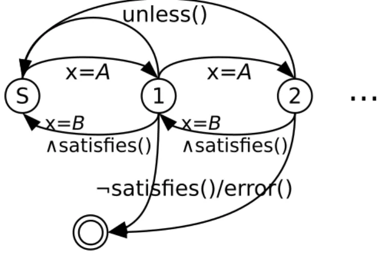
11.4.6 Each Causes Relation
Grammar of <each-causes-rule> is similar to <causes-rule> and the basic ehavior of <each-causes-rule> is similar to <before-expression> with “each” keyword. It takes a <clock-sequence> or
a single <clock> and makes sure that each time input clock ticks, there must be one target clock tick in the future. It supports <unless-statement> and <satisfies-statement> but not <if-statement>. Also the question mark in <causes-rule> cannot appear here.
11.4.7 Jitter Property
It is specified by <jitter-rule> and has the form “jitter(A, S, P, N )”, where A is the clock to be checked, S, P and N are timestamp constants. Jitter is used to make sure clock A ticks regularly with a valid margin. Suppose there are pivot ticks standing in the time line, with exact same period P between any two of them. A is supposed to tick like the pivots, however it may tick sooner or later each time, with a valid margin M within which the property is not violated. Constant S is used to specify the start timestamp offset after the scope begins.
11.4.8 Period Property
Period property is specified by <period-rule> and has the form “period(A, T, M )” where A is a valid clock and T, M are constants standing for timestamp difference. It is similar to jitter rule but it does not have any pivot. Instead, each clock tick is compared with its previous tick. This rule means that the distance between any two ticks of clock A must be T time units with a valid margin of M.
11.4.9 Throughput Property
Throughput property is specified by <throughput-rule> with the form “throughput(A, T, N )”. For clock A, throughput is defined as the count of ticks during time T. Throughput rule checks