UNIVERSITÉ DE MONTRÉAL
SMART TEXTILES FOR
TACTILE SENSING AND ENERGY STORAGE
STEPAN GORGUTSA
DÉPARTEMENT DE GÉNIE PHYSIQUE ÉCOLE POLYTECHNIQUE DE MONTRÉAL
MÉMOIRE PRÉSENTÉ EN VUE DE L’OBTENTION DU DIPLÔME DE MAITRÎSE ÈS SCIENCES APPLIQUÉES
(GÉNIE PHYSIQUE) AOÛT 2012
UNIVERSITÉ DE MONTRÉAL
ÉCOLE POLYTECHNIQUE DE MONTRÉAL
Ce mémoire intitulé:
SMART TEXTILES FOR TACTILE SENSING AND ENERGY STORAGE
présenté par : GORGUTSA Stepan
en vue de l’obtention du diplôme de : Maîtrise ès sciences appliquées a été dûment accepté par le jury d’examen constitué de :
M. FRANCOEUR Sébastien, Ph.D., président
M. SKOROBOGATIY Maksim A., Ph.D., membre et directeur de recherche Mme. BERZOWSKA Joanna, Ph.D., membre
ACKNOWLEDGMENTS
It would be very hard to acknowledge all the people that have contributed to or supported me during my Master’s studies. First of all, I would like to express my gratitude to my supervisor and research director Prof. Maksim Skorobogatiy for his constant support, assistance and guidance during my Master’s studies.
Also during the last several years, I had a pleasure to work with Dr. Jian Feng Gu and Dr. Yang Liu whom I would like to thank for their expertise in chemistry and help with fiber design and fabrication. All the time I was surrounded by wonderful colleagues: Anna Mazhorova, Andrey Markov, Hang Qu, Bora Ung. Mathieu Rozé, Alexandre Dupuis. I would like to thank them all for the helpful discussions, advices and mutual support.
Besides, I would like to give a special acknowledgement to our ex-technician Francis Boismenu and current technician Yves Leblanc. They not only provided excellent technical assistance in any situation but also were fun to work with.
Finally, I would also like to thank all those professors, employers and stuff members of Genie Physique who taught me, answered my numerous questions and helped with paperwork.
RÉSUMÉ
Durant ma maîtrise, j’ai surtout travaillé sur 2 sujets dans le domaine des textiles intelligents électroactifs.
Mon premier projet portait sur la fabrication d’un pad textile sensible au toucher utilisant des fibres capacitives en polymères. Les fibres capacitives, présentent une grande capacité et résistance, ont été fabriquées utilisant des techniques de fibrage. Pour permettre une connectivité facile, un mince fil de cuivre a été intégré dans le cœur de la fibre durant l’extrusion. Ces fibres (soft-capacitor) ont des une capacité par unité de longueur typiques de 69 nF/m, et des résistances de 5 kΩ•m. Nos mesures et nos modèles théoriques montrent que la capacité est un paramètre très stable déterminé par la géométrie utilisée, qui ne dépend pas du diamètre de la fibre ni de ses paramètres de fabriquation. La resistivité de la fibre, quant à elle, a un important coefficient thermique (positif), est très sensible aux contraintes de tension et dépend grandement des paramètre d’extrusion.
Il a aussi été démontré qu’une fibre capacitive individuelle peut servir de capteur de glissement qui permet de déterminer, sur sa longueur, la position du contact tactile en mesurant la réponse AC de la fibre à un point donné sur sa surface. La réponse électrique d’un senseur de ce type est décrite par le modèle de réseau RC, qui est en accord avec les résultats expérimentaux.
Les fibres capacitives développées sont souples, de faible diamètre, légères et n’utilisent pas d’électrolyte liquide, donc elles sont idéales pour l’intégration dans les produits textiles. À la fin du chapitre, nous avons démontré qu’en tissant un ensemble de fibres capacitives en 1 dimension (fibres parallèles), il est possible de tisser un senseur tactile en 2 dimensions. Les performances de ce senseur ont été caractérisées et une bonne isolation entre les canaux a été démontrée. Un tel senseur possède aussi des fonctionnalités multi-touch.
Mon deuxième projet portait sur l’assemblage de cellules Li-ion flexibles et étirables, leur intégration dans un textile et leur caractérisation électrique dans un contexte de «textiles intelligents». L’aspect chimique de ces cellules a été développé par mon collègue Y.Liu, qui a réussi à intégrer la cathode (LiFePO4), l’anode (Li4Ti5O12) et l’électrolyte solide (PEO) dans un système de cellule électrochimique souple. J’ai démontré de façon expérimentale que des batteries de cellules flexibles peuvent être fabriqués en grande feuilles, puis coupées en fines
lanières et tissées dans les textiles. Les performances électrochimiques des cellules ont été caractérisées de façon rigoureuse et elles se sont avérés être inférieures aux cellules basées sur des électrodes en poudre et des électrolytes liquides. Cependant leur performances cycliques, leur souplesse et leur texture s’apparentant à du cuir les rendent bien adaptées à des applications de «textiles intelligents». Même si leur tension électrique de fonctionnement est relativement basse (~0.3V), lorsque plusieurs d’elles sont connectées en série, le voltage net peut être suffisamment grand pour des applications pratiques. Finalement, comme démonstrateur de technologie, j’ai testé une batterie textile faite de 8 cellules en bande flexibles tissées ensemble et connectées en série pour alimenter une DEL de 3 volts pendant plusieurs heures.
ABSTRACT
During my master’s I have mainly worked on two subjects in the research area of electroactive smart textiles.
My first project involved building a touch sensitive textile pad using original home-made all-polymer soft capacitor fibers. The capacitor fibers featuring relatively high capacitance and resistance were fabricated using fiber drawing technique. For the ease of connectorization, a thin copper wire was integrated into the fiber core during drawing procedure. Soft-capacitor fibers have a typical capacitance per unit length of 69 nF/m, and a typical resistivity parameter of 5 kΩ•m. Our measurements and theoretical modeling show that the fiber capacitance is a very stable, geometry defined parameter independent of the fiber diameter, and fiber fabrication parameters. In contrast, fiber resistivity has a very strong positive temperature coefficient, it is highly sensitive to stretching, and it is strongly dependent on the fiber drawing parameters.
Next, an individual capacitor fiber was demonstrated to act as a slide sensor that allows determining the touch position along its length by measuring the fiber AC response at a single point at the fiber surface. Electrical response of such a sensor was described by the RC ladder model, with the modelling data in excellent agreement with experimental observations.
Developed capacitor fibers are soft, small diameter, lightweight and do not use liquid electrolytes, thus they are ideally suited for the integration into textile products. At the end of the chapter, we have demonstrated that by weaving a one dimensional array of capacitor fibers (in parallel to each other) a fully woven 2D touchpad sensor could be build. Performance of a touchpad sensor was then characterised and the absence of the inter-channel crosstalk was confirmed. We also note that a 2D touchpad has a partial multi-touch functionality.
My second project involved assembly of flexible and stretchable Li-ion batteries, their integration into a textile, and their electric characterization in a view of smart textile applications. The chemistry for the battery was developed by my colleague Y. Liu who has combined the relatively conventional Li battery materials including LiFePO4 cathode, Li4Ti5O12 anode and PEO solid electrolyte into a non-conventional soft electrochemical battery system. I have experimentally demonstrated that flexible batteries can be first cast as sheets, and then cut into thin strips, and finally integrated into textile using conventional weaving techniques. The
electrochemical performance of the film batteries was extensively characterized and found to be poorer compared to the performance of batteries based on the powder electrodes and liquid electrolytes. At the same time, cycling performance of the solid film batteries was stable, and together with their soft leather-like feel and appearance, this makes such batteries well suitable for smart textile applications. Although operating voltage of a single flexible battery is relatively low (~0.3V), nevertheless, when several of them are connected in series, the net voltage can be large enough for practical applications. Finally, as a demonstrator of the technology I have tested a textile battery comprising 8 flexible battery strips woven together and connectorized in series to power up a 3V LED over several hours.
TABLE OF CONTENTS
ACKNOWLEDGMENTS ... iii RÉSUMÉ ... iv ABSTRACT……….v TABLE OF CONTENTS………vi LIST OF FIGURES ... xiLIST OF ABBREVIATIONS AND SYMBOLS ... xv
INTRODUCTION ... 1
SCIENTIFIC OUTCOMES OF MY MASTER’S RESEARCH ... 2
CHAPTER 1 Literature Review ... 3
1.1 Smart textiles ... 3
1.2 Touch sensitive technologies ... 4
1.3 Smart Fibers ... 6
1.4 Energy storage textiles ... 7
CHAPTER 2 Tactile sensing textiles using soft capacitance fibers ... 10
2.1 Soft capacitor fibers for electronic textiles ... 10
2.1.1 Fiber materials and fiber fabrication ... 10
2.1.2 Capacitor fiber designs ... 12
2.1.3 Capacitor fiber connection, and potential applications ... 14
2.2 Electrical properties of the soft capacitor fibers... 17
2.2.1 Setup for characterization of the isolated capacitor fiber ... 17
2.2.2 RC ladder network model of a soft capacitor fiber fully covered with a foil probe 18 2.2.3 Frequency dependent response of the capacitor fibers ... 21
2.2.5 Effect of the temperature of operation on the fiber electrical properties ... 24
2.2.6 Effect of the fiber drawing parameters ... 25
2.3 Capacitor fiber as a 1D distributed touch sensor ... 26
2.3.1 Electrical response of a single capacitor fiber ... 28
2.3.2 RC ladder network model for the capacitor fiber featuring one highly conductive, and one highly resistive electrodes ... 31
2.3.3 Interpreting electrical data from a single fiber touch sensor... 39
2.3.4 Effect of the fiber length on sensitivity... 40
2.3.5 Effect of the operational frequency on sensitivity ... 41
2.4 Fully woven 2D touch pad sensor using 1D array of capacitance fibers ... 42
2.4.1 Sensor design and fabrication ... 42
2.4.2 Cross-talk and channel calibration ... 44
2.5 Conclusions ... 45
CHAPTER 3 Flexible, Solid Electrolyte-based Lithium Battery for Smart Textile Application . 46 3.1 Fabrication and characterization of the solid electrolyte battery ... 46
3.1.1 Characterization methods... 47
3.2 Properties of the polymer electrolyte ... 48
3.3 Properties of the flexible electrodes ... 51
3.4 Electrochemical properties of flexible batteries ... 53
3.4.1 Open circuit voltage measurements ... 53
3.4.2 Charge-discharge measurements ... 55
3.4.3 Effect of solvents and PEO on electrode structure. ... 57
3.5 Textile battery prototype performance ... 58
CHAPTER 4 General discussion, perspectives and Conclusions ... 61
4.1 Touch sensitive textile ... 61
4.2 Flexible batteries ... 62
REFERENCES ... 63
LIST OF FIGURES
Fig. 2-1 (a) Schematic of a cylindrical capacitor fiber preform featuring a spiralling multilayer comprising two conductive and two isolating films. (b) Schematic of a cylindrical capacitor fiber with two electrodes in the center. (c) Schematic of a rectangular preform prepared by encapsulating a zigzaging stack of two conductive and an isolating layer inside a rectangular PMMA tube. ... 12 Fig. 2-2 Design I: hollow core fiber with the first electrode lining the inside of a holow core, and the second plastic electrode wrapping the fiber from outside. During drawing fiber hollow core can be left open (a) or collapsed (b) depending on the application requirement. Design II: Hollow core fiber can be drawn with a metallic electrode in the center. Such an electrode can be a copper wire (c) in contact with the plastic electrode lining the hollow core. Design III: fiber containing two hollow cores. The cores are lined with two plastic electrodes electrically separated from each other. Fiber is drawn with two copper wires threaded through the hollow cores in the preform (d). Design IV: square fiber capacitor. Fiber features a zigzaging stack of two plastic electrodes separated with an electrically isolating PC layer (e). Furthermore, two metallic electrodes are placed in contact with plastic electrodes, and the whole multilayer is encapsulated inside a square PMMA tube. ... 13 Fig. 2-3 (a) Capacitor fiber fabricated from the preform shown in Fig. 2-2(c). The fiber features a central 100m-thick copper wire, as well as an exposed conductive plastic electrode on the fiber surface. (b) To perform electrical characterization of the fibers, embedded copper wire is used as the first electrical probe, while the second electrical probe is an aluminum foil wrapped around the fiber conductive surface. The inset is an enlarged view of the fibers with single and double copper wire electrodes. ... 16 Fig. 2-4 Schematic of the measurement setup ... 18 Fig. 2-5 Ladder network model of the capacitor fiber fully covered with a foil probe. ... 18 Fig. 2-6 Comparison of experimental data and model predictions of frequency responses of a fiber capacitor. (a) Effective capacitance vs. frequency. (b) Effective resistance vs. frequency. 22
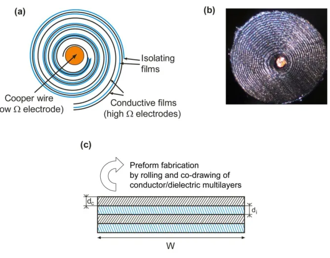
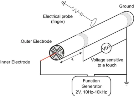
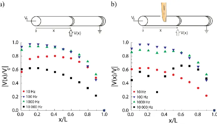
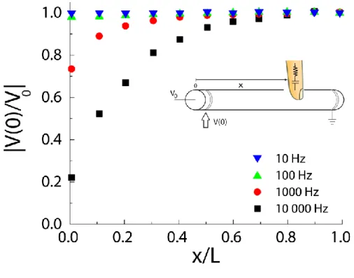
Fig. 2-7 Dependence of the (a) fiber capacitance and (b) fiber resistivity on fiber length. Red and blue data sets correspond to the two fiber samples of different diameters drawn from the same preform. Insets: dependence of the (a) fiber capacitance per unit length CF/L and (b) fiber resistivity factor RF·L on the fiber length. ... 23 Fig. 2-8 Effect of the temperature of operation on electrical properties of a capacitor fiber. (a) Capacitance per unit of length CF/L. (b) Resistivity factor RF•L. Sample #1 has a diameter of 840 m and a length of 135 mm. Sample #2 has a diameter of 930 m and a length of 136 mm. ... 24 Fig. 2-9 (a) Schematic of a capacitor fiber featuring a spiraling multilayer comprising two conductive and two isolating films. Black curves represent two conductive films, while blue curves represent isolating films. (b) Photo of the crosssection of a drawn capacitor fiber with a cooper wire embedded in the center. (c) Fiber preform is made by co-rolling four polymer layers (2 conductive and two isolating) into a swiss-roll structure. The number of resultant layers in a spiral structure is proportional to the width of the unrolled multilayer. In the drawn fiber, thicknesses of the conductive dc and isolating di layers can be smaller than 10m, while the unwrapped width W of the layers fitting into a 1mm diameter fiber can be in excess of 3cm. ... 27 Fig. 2-10 Schematic of a 1D slide sensor based on a single capacitor fiber. ... 29 Fig. 2-11 Voltage distribution along the outer fiber electrode for (a) an isolated fiber (b) a fiber touched with an equivalent human probe. Four data sets correspond to the different driving frequencies of 10 Hz, 100 Hz, 1 kHz and 10 kHz. Voltage distribution along the fiber touched with a probe shows dip in the vicinity of a touching position. ... 30 Fig. 2-12 Voltage measured at the extremity of a capacitor fiber opposite to the fiber grounded end. ... 31 Fig. 2-13 Ladder RC network model of a stand-alone capacitor fiber. (a) The fiber is modeled as a sequence of fiber crossections of small length dx connected in series via longitudinal resistive elements (high resistivity outer electrode), while we assume that the inner copper electrode has a constant potential along its length. (b) Electrical response of an individual fiber crossection is modeled as an RC network where transverse resistivity elements are connected via capacitance elements. (c) Also dR on the scheme above corresponds to longitudinal resistance element, l
dR and dC
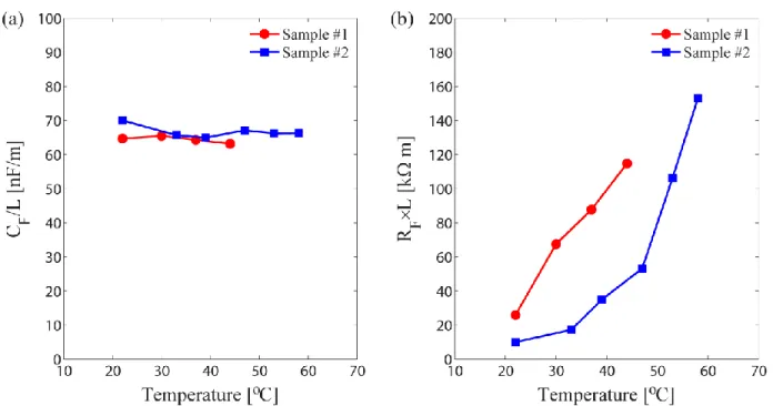
are frequency dependent resistance and capacitance of an individual fiber crossection of length dx. One can show that equivalent circuit that describes electrical response of an individual fiber crossection is given simply by the frequency dependent resistivity connected in series with frequency dependent capacitance. Finally, electrical response of a fiber is modeled as another RC network with frequency dependent resistivity and capacitance. ... 32 Fig. 2-14 The ladder network model of a 1D slide sensor. The fiber is assumed to be touched at a position xb with a finger having effective electric parameters Rb, Cb. Moreover, to simplify comparison with experiment we include in our model the effective circuit (with parameters Rp, Cp) of an oscilloscope probe used in our measurements; the probe is attached at a position xp... 34 Fig. 2-15 Fiber response to the touch of the equivalent human probe - comparison between predictions of the RC ladder model and experimental data. (a) Response at 10 kHz of the three distinct fibers of the same length and different capacitances Ct=40 nF.m−1, Ct =65 nF.m−1, Ct=95 nF.m−1. The rest of the geometrical and electrical parameters of the fibers are similar to each other. (b) Response at 1 kHz and 10 kHz of the two distinct fibers of the different lengths. The rest of the geometrical and electrical parameters of the fibers are identical to each other as shorter fiber was obtained by cutting a longer fiber in half. ... 37 Fig. 2-16 Typical time resolved response of a 1D slide sensor. Dips in the measured voltage correspond to the touch and release events. ... 39 Fig. 2-17 The woven touchpad sensor. (a) Schematic representation of the woven 2D touchpad sensor featuring a one dimensional array of the capacitor fibers. All the connections to and from the fibers are done using a 120 m-diameter cooper wire (denoted by red lines). Fibers in the array have the common ground and a common source, however, they are interrogated individually. Analog output of the ADC board is used as a function generator that provides a sinusoidal signal at 1 kHz with an amplitude of 4 V. (b) Weaving a two dimensional touchpad sensor on a Dobby loom. (c) Photograph of the woven touchpad connected to the ADC board, as well as the monitor image of a textile with an interpreted touch position. ... 43 Fig. 2-18 Recorded voltage response as a function of time for the three neighboring fibers in the woven touchpad. No detectable cross-talk between the fibers was observed. Dips on the graphs correspond to the individual touch events that take place at different moments in time. ... 44
Fig. 3-1 Fabrication procedure of the all-solid flexible battery а) First cathode film is created and completely dried, then a solution for the separator layer was poured onto the cathode layer and a two-layer system is created after drying. Finally, the cathode layer mix was poured onto the two layer system and dried. ... 46 Fig. 3-2 The complex equivalent circuit for the battery system with polymer electrolytes. Cg is the geometrical capacitance, Rs is the polymer electrolyte resistance, Ce is the electrode and electrolyte interfacial capacitance and Re is the electrode/electrolyte interfacial resistance, W is the Warburg impedance. ... 48 Fig. 3-3 Top row: photographs of a flexible battery made of binding individual cathode, anode and polymer electrolyte films. Middle row: resulting battery is highly stretchable. Bottom row: battery stripes (black) woven into a textile (blue and red cotton threads) using Dobby loom. The stripes are connectorized in series with conductive threads (metallic brown). Two textile electrodes are formed by the conductive threads at the textile extremities. ... 52 Fig. 3-4 The cyclic voltammetry results of a) anode powder sample, b) anode film sample ... 53 Fig. 3-5 Constant current charge-discharge curves of the two flexible batteries with a solid PEO:LiI polymer electrolyte separator layer. a) Electrodes with 26.7% of PEO. b) Electrodes with 50 % of PEO. ... 56 Fig. 3-6 WAXD results for the a) powder (no PEO) and film (50% PEO) cathode b) powder (no PEO) and film (50% PEO) anode. ... 58 Fig. 3-7 Top: Textile battery is made of 8 battery stripes woven with cotton thread and connectorized in series using copper and aluminium wires (one per stripe per side) as electron collectors. The resultant battery is powerful enough to light up a 3V LED for several hours. Bottom: the charge-discharge curves of the textile battery. ... 59
LIST OF ABBREVIATIONS AND SYMBOLS
PCE Power conversion efficiency OPV Organic photovoltaic cell Tg Glass transition temperature
PE Polyethylene
PVDF Polyvinylidene fluoride
PC Polycarbonate
PET Polyethylene terephthalate PMMA Polymethyl methacrylate LDPE Low density polyethylene HDPE High density polyethylene
CB Carbon black
ADC Analog-to-Digital Convertor
1D One dimensional
2D Two dimensional
PEG Polyethylene glycol PEO Poly Ethylene Oxide
WAXD Wide-angle X-ray scattering KVL Kirchhoff's Voltage Law KCL Kirchhoff's Current Law Rref Reference resistance Current frequency
Rt Transverse resistance of the fiber
ρv Volume resistivity
L Length of the fiber,
W Width of the conductive electrodes dc Thickness of the conductive electrodes
di Thickness of the rolled isolating films
N Number of turns of the conductive electrode
C Fiber capacitance
Dielectric constant of the isolating films
0 Permeability of the vacuum
xb Position of the finger touch on the fiber surface
xp Position of the probe attachment on the fiber surface
Rb Effective resistance of the finger
Cb Effective capacitance of the finger
Rp Effective resistance of the probe and oscilloscope
Cp Effective capacitance of the probe and oscilloscope
L Characteristic length of the current decay
Ce Capacitance of the anode/electrolyte or cathode/electrolyte double layer
Re Charge transfer resistance
INTRODUCTION
Smart textiles that can sense and respond to environmental stimuli of different nature (mechanical, thermal, chemical, electrical, magnetic, etc.) currently attract considerable attention due to a multitude of commercial opportunities and advanced applications in sport and wellness industries, work ware and military. In this work, I address two narrow topics related to the development of smart electroactive textiles.
The first research topic discussed in this work concerns the fabrication of tactile sensors based on recently developed soft capacitor fibers. In their crossection, the fibers feature a periodic sequence of hundreds of conductive and isolating plastic layers positioned around metallic electrodes. The fibers are fabricated using a fiber drawing method, where a multi-material macroscopic preform is drawn into a sub-millimeter capacitor fiber in a single fabrication step. I start with an overview of the different tactile sensors developed to the present moment, then I continue with a discussion of fabrication of soft capacitor fibers, then I introduce a theoretical model to describe the electrical response of a single capacitor fiber using an electrical ladder network model, and, finally, I show that such fibers can be used as touch-based slide sensors. The effects of different parameters on the sensing performance of a soft capacitor fiber are also studied. Softness of the fiber materials, absence of liquid electrolyte in the fiber structure, and high capacitance of such fibers make them ideally suited for integration into textiles. As a proof of concept, the prototype of a woven touchpad sensor featuring a one dimensional array of capacitor fibers is presented in the final section and its performance is characterized.
The second research direction described in this thesis is the fabrication and the characterisation of a flexible and stretchable battery composed of a strain free LiFePO4 cathode, a Li4Ti5O12 anode and a solid polyethylene oxide (PEO) electrolyte as a separator layer. Featuring a solid thermoplastic electrolyte as a key enabling element, this battery is potentially extrudable or drawable into fibers, which are directly compatible with the weaving process used in smart textile fabrication. As a proof of principle, a large battery sample made of several long battery strips woven into a textile and connectorized with conductive threads was demonstrated to light up an LED.
SCIENTIFIC OUTCOMES OF MY MASTER’S RESEARCH
Publications, conference proceedings and presentations resulting from my work during the master’s studies:
Journal Publications
1. Y. Liu, S. Gorgutsa, C. Santato, and M. Skorobogatiy “Flexible, Solid Electrolyte-Based Lithium Battery Composed of LiFePO4 Cathode and Li4Ti5O12 Anode for Applications in Smart Textiles”, Journal of The Electrochemical Society, vol. 159 (4), pp. A349-A356 (2012)
2. S. Gorgutsa, J.F. Gu and M. Skorobogatiy “A woven 2D touchpad sensor and a 1D slide sensor using soft capacitor fibers”, Smart Mater. Struct., vol. 21, 015010 (2012)
3. J.F. Gu, S. Gorgutsa, and M. Skorobogatiy "Soft capacitor fibers using conductive polymers for electronic textiles," Smart Mater. Struct., vol. 19, 115006 (2010)
4. J.F. Gu, S. Gorgutsa, and M. Skorobogatiy "Soft capacitor fibers for electronic textiles," Appl. Phys. Lett., vol. 97, 133305 (2010)
Conference Proceedings
1. A. Mazhorova, J.F. Gu, S. Gorgutsa, M. Peccianti, R. Morandotti, T. Ozaki, M. Tang, H. Minamide, H. Ito, M. Skorobogatiy, "THz metamaterials using aligned metallic or semiconductor nanowires," We-P.31, The 35th International Conference on Infrared, Millimeter, and Terahertz Waves, IRMMW-THz 2010.
Book chapters (to be published)
1. S.Gorgutsa and M. Skorobogatiy,“Tactile sensing textiles using soft capacitance fibers” in Multi-disciplinary know-how for smart textile developers, Tünde Kirstein ed. (Woodhead Publishing Ltd, 2012), Ch.5.
2. S.Gorgutsa, J. Berzowska and M. Skorobogatiy, “Photonic Textiles using optical fibers” in Multi-disciplinary know-how for smart textile developers, Tünde Kirstein ed.(Woodhead Publishing Ltd, 2012), Ch.3.
CHAPTER 1
LITERATURE REVIEW
1.1 Smart textiles
Fuelled by the rapid development of micro and nanotechnologies, and driven by the need to increase the value of conventional textile products, fundamental and applied research into smart textiles (or high-tech textiles) has recently flourished.
Generally speaking, textiles are defined as “smart” if they can sense and respond to environmental stimuli that can be of mechanical, thermal, chemical, electrical or magnetic nature. Some of the first uses of smart textiles were in military and medical applications. For example, with the support of US Naval Department in 1996 Georgia Tech has developed a garment called Wearable Motherboard (with the commercial name of Smart shirt).[22], [23] The Wearable Motherboard is a fabric featuring woven electric wires and/or optical fibers that serve as a flexible information bus. To integrate electronics directly into textiles leads to the so called technique of “wearable computing” or “E-textiles” [24]-[26]. Another application of smart textiles is in harnessing (and recently in storage) of the energy of human motion or the energy of various ambient fields, such as electromagnetic fields. Electric energy generation from human motion, for example, has been recently demonstrated using piezoelectric fibers made of ceramic materials like PZT (lead zirconate-titanate) as well as polymers such as PVDF (polyvinylidene fluoride) [27] , [28]. Smart textiles can also be found their usage in heat-storage and thermo-regulated clothing [29], [30] and various wearable sensors including those for biomedical monitoring [31]. For example, conventional fabrics coated with a thin conducting polymer layer possess remarkable properties of strain and temperature sensing [11]. A multi-layer structure consisting of two conductive fabrics separated by a meshed non-conductive one can be used as a pressure sensor [10]. Sensing garments for monitoring physiological and biomechanical signals of human body have already been invented for healthcare [33] and sports training [34]
Applications of smart textiles have been demonstrated from responsive seats in automobiles [35] where textiles can indicate the level of comfort of an individual passenger, to apparel with tuneable or adjustable color and appearance in fashion and design [36]. Recently various textile
based displays became especially popular. One of the most commonly used inks for this new type of displays is thermochromic ink that change color based on temperature. Typically such inks are deposited on textile [16], [17] or on paper [18] and then are actuated by either electrically conductive yarn that is woven into the fabric or by incorporated wires. When powered up, the conductive yarn heats up and in turn actuates the thermochromic inks to change the color. In ‘Mosaic Textiles’ [18], authors use liquid crystal inks which work on the same principle as thermochromic inks, actuated by conductive yarn. However most of such displays have several major limitations. First, they can only demonstrate images that are pre-selected during the manufacturing. Second, resolution of the thermochromic displays is limited by the size of the electrically conductive heaters, and by the lateral and diffusion of heat emanating from the heaters. Finally, the displays that use only heating source such as body heat or conductive yarn without any cooling method, lack controllability as it may take from 10 seconds to several minutes for such a display too go back to idle state. Those thermochromic ink displays that have a cooling system typically require high-cost and complex standard “rigid” electronics.
Another popular concept is electrochromic textiles [20] the idea is similar to thermochromic textiles but color changes is achieved as a result of the oxidation or the reduction of the material by electrochemical means [21].
As it was already mentioned in this work two research directions in smart textile domain are studied: touch sensitive textiles and flexible energy storage textiles.
1.2 Touch sensitive technologies
Touch sensing as a human interface device (HID) technology is becoming increasingly popular and ubiquitous finding its applications in smart phones, computers and responsive garments to name a few. Various touch sensing systems have been developed based on the different physical principles including resistive, capacitive, infrared, surface acoustic wave, electromagnetic, near field imaging, etc. Resistive [22] and capacitive [23] methods have been widely used in conventional touch screens of the commercial products such as mobile phones, PDAs, and consumer electronics devices. Resistive touch screens are composed of two material sheets that are coated with a resistive material, commonly indium tin oxide (ITO), and separated by an air gap or microdots. When a finger presses the screen, the two sheets are connected at the
touch position which changes the current flow in the screen. A sensing circuit then detects changes and locates the touch position. A capacitive touch sensor is based on the capacitive coupling effect. A typical design involves coating the screen with a thin, transparent metallic layer, in order to form a collection of capacitors on the surface. When a user touches the surface, the disturbance caused by the finger changes the capacitance and current that flows on the display.
A significant limitation for most of these technologies is that they are only capable of detecting a single touch. Multi-touch techniques allow touch screens to recognize touches of multiple fingers or inputs of multiple persons simultaneously. The multi-touch detection mechanisms can be classified into three categories: sensor array, capacitive sensing, and vision and optical based ones. A sensor array touch surface consists of a grid of touch sensors that work independently. When a user exerts multiple touches on the surface, the system can indentify activated sensors and determine these touch positions simultaneously. An example, originally proposed by Lee et al. [24], is FMTSID (Fast Multiple-Touch-Sensitive Input Device) - one of the first multi-point touch sensor-based devices. The system consists of a sensor matrix panel, rows of the sensors, A/D converter and a control CPU. The design of the sensor matrix is based on the technique of capacitance measurement between a fingertip and a metal plate. A capacitive touch method uses the capacitive coupling between two conductors to sense a touch. Typically, the touch surface contains a mesh of horizontal and vertical antennas which function as either a transmitter or a receiver of electric signals. Examples based on this technology include Rekimoto’s SmartSkin [25], and DiamondTouch developed by Dietz and Leigh [26].
In addition to touchscreens, touch sensors with force sensing ability has been studied as tactile sensors for many years [27]. Such sensors have found their applications in artificial skin for robot applications [28], minimally invasive surgery [29], wearable computers [30], and mobile or desktop haptic devices [31]. Up to date tactile sensors have mainly focused on silicon-based sensors that use piezoresistive [32], [33] or capacitive sensing mechanism [34], [35], [36]. The silicon tactile sensors have limitations of mechanical brittleness, and hence are not capable of sustaining large deformations. Polymer-based tactile sensing approaches that use piezoelectric polymer films [37], [38], [39], pressure-conductive rubber [40], carbon fiber based polymer composite [41] and conductive polymers [42], have been reported as well. These sensors provide
good spatial resolution but the applied force range is low due to the limited thickness of a membrane.
So far, capacitive sensing is probably the most promising technique for the textile based touch sensors as it does not depend on the applied mechanical force (including bends and stretching) and also enables multi-touch and gesture recognition functionality.
1.3 Smart Fibers
With the constant improvement of the technology, there is no doubt that smart textiles will soon become an integral part of our daily life [43]-[45]. However nowadays most of the “smart” functionalities in the currently existing smart apparel are typically enabled by various point devices attached to a textile matrix. Such point devices (electronic chip-sets, for example) are typically not compatible with the weaving process and, thus, have to be introduced onto a textile surface in a post-processing step. This, in turn, makes fabrication of smart apparel labour intensive and therefore expensive. Additionally, most of the point devices such as sensors and batteries are not flexible, and therefore wearability of such garments is usually problematic. Limitations introduced by the rigid point devices motivated recent effort into the development of flexible electronic components. For example, a flexible energy storage devices based on nanocomposite paper was reported [46]. The device, engineered to function as both a lithium-ion battery and a supercapacitor, can provide the long and steady power output.
Ideally, if all the electronic functionalities could be implemented in a fiber itself, such fibers would provide a perfect building material for smart apparel as they could be naturally integrated into textiles during weaving process. Because of the technical complexity of integration of advanced electronic functionalities into a textile fiber, currently there are only few examples of such fibers. Thus, a conductive fibre prepared from ultra-high molecular weight polyaniline by continuous wet spinning techniques was recently commercialized [47]. The researcher group of Wang [48] has developed a microfiber nanogenerator composed of a pair of entangled fibers which can generate electrical current using the piezoelectric effect. It has been demonstrated that commodity cotton threads can be transformed into smart electronic yarns and wearable fabrics for human biomonitoring using a polyelectrolyte-based coating with carbon nanotubes (CNTs) [49]. A stretchable, porous, and conductive textiles have recently been invented by a simple
“dipping and drying” process using a single-walled carbon nanotube (SWNT) ink [50]. The loading of pseudocapacitor materials into these conductive textiles can lead to a 24-fold increase of the areal capacitance of the device. Finally, several groups [51]-[53] have recently demonstrated organic all-fiber transistors which can potentially allow creation of electronic logic circuits by weaving.
To integrate tactile sensors in the smart-textiles applications one could, for example, use arrays of conventional rigid electric devices embedded into a textile matrix, as it was done in early prototypes of the “smart apparel”. But as it was already mentioned this approach does not provide acceptable wearing comfort or good mechanical properties. This motivated recent efforts into the development of truly wearable smart textiles.
Recently there have been several reports on the capacitor fibers compatible with a textile weaving process. By adding an external inductance such fibers make a resonant LC circuit, thus allowing the use of many highly sensitive resonant detection techniques which are able to detect small changes in the capacitor structure. Among several proposals for a capacitor fiber we note a multicore fiber capacitor in the form of a bundle of ~50m-sized coaxial cables connected in parallel on a micro-level [54]. However, such capacitors were never actually fabricated.
One important note should be made regarding various smart textiles discussed above, typically all prototypes are powered by conventional external power supply or small batteries. However, truly wearable smart textiles will also require wearable, flexible and environmentally friendly power sources.
1.4 Energy storage textiles
Broadly speaking, the advancements in flexible batteries have been in the following categories: (a) flexible organic conducting polymers [55]-[58], (b) bendable fuel cells [59], (c) polymer solar cells [60]-[62] and (d) flexible lithium polymer batteries [48], [63], [64].
Conducting polymers are particularly interesting materials to fabricated energy storage devices as they possess inherent fast redox switching, high conductivity, mechanical flexibility, low weight and could be integrated into existing production processes [65]. Plus conductive polymers are more environmentally friendly and cost-efficient than most metal containing electrode materials, however insufficient cycle stabilities and the high self-discharge rates often
limit their applicability in commercial battery systems. One approach to improve the performance of nonmetal-based energy storage devices would be to use composite electrode materials of conductive polymers deposited as thin layers on a suitable large surface area substrate.
Flexible components, especially current collectors, are crucial parts of bendable fuel cells and could be implemented, for example, by preparing flexible membrane electrode assemblies [66]. Swedish company «myFC» developed flexible fuel cells (called FuelCellSticker) that convert hydrogen into electricity via proton exchange membrane. Except these quite complex solutions there are bendable on-chip fuel cells which were fabricated on flexible COP films. Such fuel cells fabricated on a flexible polymeric substrate were reported for the first time by Ito et al. [67]
Polymer solar cells have certain attractive features as a power source for the smart textile solutions. First of all, active materials used for fabrication devices are soluble in most of common organic solvents. Second, polymer solar cells have potentials to be flexible and to be manufactured in a continuous printing process. Various printing and coating technologies have been proven their compatibility with semiconducting polymer processing. Still, power conversion efficiency (PCE) of such solar cells is low (PCE about 6% [68], [69] was recently reported). Also stability of organic photovoltaic cells (OPVs) without encapsulation have very short lifetime, ranging from a few minutes to a few days [70]. The mechanism of the degradation of OPVs through difference pathways was investigated by Jørgensen et al. [71]. The organic materials and metal used as the electrodes react with oxygen and water which are diffused from both electrodes or lateral of the device are believed the major reason causing short lifetime of OPVs.
Recently, a rechargeable textile battery was created by Bhattacharya et al [51]. It was fabricated on a textile substrate by applying a conductive polymeric coating directly over interwoven conductive yarns. Approaches to produce stretchable and foldable integrated circuits have also been reported. This includes integrating inorganic electronic materials with ultrathin plastic and elastomeric substrates [52] and printing high viscous conductive inks onto nonwoven fabrics [53]. Among those flexible batteries, the lithium polymer battery has taken much attention for its potential in electric vehicle applications. It employs a solid polymer electrolyte,
which can act both as the electrolyte and the separator, with the aim of improving battery design, reliability, safety, and flexibility.
There are two features shared by the majority of existing flexible batteries that make them ill-suited for applications in smart textiles. The first one is that conventional polymer electrolytes and binders used in lithium batteries to blend anode, cathode and conducting materials are processed with organic solvents, which are poisonous and caustic and, thus, do not fit well with wearables. The second one is the fact that, at present, flexible film batteries are not extrudable or drawable to form fibers or strips, which are the necessary building block for smart textile fabrication.
CHAPTER 2
TACTILE SENSING TEXTILES USING SOFT CAPACITANCE FIBERS
In this section fabrication and characterization of the touch sensitive textile prototype is discussed. This prototype is based on the novel all-polymer soft capacitor fibers recently developed in our research group.
2.1 Soft capacitor fibers for electronic textiles
Another novel type of electronic fiber was recently developed in our laboratory - high capacitance, soft fiber from conductive polymer composites. One key advantage of our fibers is that they do not require the use of electrolytes for their operation, which is especially desirable for wearable applications. Another key advantage is that the fibers can be made fully polymeric (no metallic electrodes) and very soft for applications in wearable sensing. Because of the relatively high capacitance of the fiber (60-100nF/m) it can be also used for energy storage applications. In terms of capacitance our fibers take an intermediate position between the coaxial cables and supercapacitors. Thus, capacitance of a coaxial cable with comparable parameters is typically 1000 times smaller than that of our fibers.
2.1.1 Fiber materials and fiber fabrication
The soft capacitor fibers are fabricated by the fiber drawing technique which consists of three steps. The first step involves rolling or stacking conductive and dielectric films into a multilayer preform structure. During the second step the preform is consolidated by heating it to temperatures somewhat above the polymer glass transition temperature (Tg). Consolidation is needed as the diffusion of the polymer molecules through interfaces of adjacent layers fuses these layers together thus reduces the effect of property mismatch of different materials in the drawing process. Finally, at the third step consolidated preform is drawn into fibers using fiber drawing tower. Drawing is typically performed at temperatures higher than the polymer Tg. During successful drawing the resultant fibers generally preserve the structured profile of a preform, thus, fibers with very complex microstructure can be fabricated via homologous reduction (during drawing) of a macrostructure of the preform. Described drawing technique is
directly analogous to the one used in manufacturing of microstructured polymer optical fibers [72].
Flexible multilayer capacitors presented in this Chapter generally consist of two conducting polymer layers serving as two electrodes of a capacitor, and two isolating polymer separator layers. To result in a successful drawing the preform materials should be compatible with each other in terms of their rheological and thermo-mechanical properties. In the first tests an attempt to draw thin continuous layer of low-melting temperature metal sandwiched between the two isolating polymer layers was made. As a metal Bi58/Sn42 alloy with a melting point of 138℃ was used. Various polymers were tested as isolating layers. However, it was found that in all cases it was difficult to preserve the laminated structure with a thin metal foil during drawing process. Particularly, when melted, metal foil would break into wires during drawing, thus destroying the continuous electrode structure. This observation have been rationalized by noting that the visco-elasticity ductility and interfacial tension of alloy and the surrounding polymer cannot match well at drawing temperatures. For example, at the temperature for the polymer to be drawn into fibers the viscosity of melted metal becomes very low, thus it is easy for a thin sheet of melted metal to develop a flow instability and form several larger wires to minimise surface energy associated with a polymer/metal interface. Another potential problem during drawing of metal sheets is that when the polymer surrounding the molten metal becomes too soft it can no longer hold the melt; as a consequence a large drop of metal would form at the preform end even before drawing starts, thus draining the rest of a preform from metal. From these initial experiments it was concluded that drawing of a thin metallic sheet sandwiched between two plastic sheets is in general problematic due to strong mismatch of the material properties during drawing process.
After realizing the challenge of drawing metallic electrods in the form of thin sheets, a natural option to remedy this problem was to substitute metals with thermoplastic conductive polymers as electrodes. Unfortunately, thermoplastic intrinsic conductive polymers suitable for drawing are not available commercially. The only thermoplastic conductive polymers which are currently available commercially are either carbon black filled or most recently carbon nanotube filled films. In this research polyethylene (PE)-based carbon black filled films (BPQ series) provided by Bystat International Inc. were used. The film, with a thickness of 91 m, has a surface resistivity of 17 K/sq. The messured volume resistivity is around 2.2 ·m in the
directions along the surface. To find the isolating materials that can be co-drawn with this conductive film, various polymer films such as polyvinylidene fluoride (PVDF), polycarbonate (PC), polyethylene terephthalate (PET), polymethyl methacrylate (PMMA), and others were tested. Among all the attempted polymers the two best materials for the isolating layer were found, which appeared to be low density polyethylene (LDPE) film or a polycarbonate film.
2.1.2 Capacitor fiber designs
Originally, three distinct fiber capacitor geometries that were developed. They all share the same concept but each of them poses its own features. The first fiber type has a cylindrical geometry with two plastic electrodes in the form of a spiralling multilayer (see Fig. 2-1(a)). Central part of a fiber was either left empty with the inner plastic electrode lining up the hollow core, or a metallic electrode was introduced into the hollow core during drawing, or the core was collapsed completely thus forming a plastic central electrode. In all these fibers, the second electrode was wrapped around the fiber.
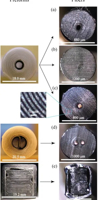
Fig. 2-1 (a) Schematic of a cylindrical capacitor fiber preform featuring a spiralling multilayer comprising two conductive and two isolating films. (b) Schematic of a cylindrical capacitor fiber with two electrodes in the center. (c) Schematic of a rectangular preform prepared by encapsulating a zigzaging stack of two conductive and an isolating layer inside a rectangular PMMA tube.
Fig. 2-2 Design I: hollow core fiber with the first electrode lining the inside of a holow core, and the second plastic electrode wrapping the fiber from outside. During drawing fiber hollow core can be left open (a) or collapsed (b) depending on the application requirement. Design II: Hollow core fiber can be drawn with a metallic electrode in the center. Such an electrode can be a copper wire (c) in contact with the plastic electrode lining the hollow core. Design III: fiber containing two hollow cores. The cores are lined with two plastic electrodes electrically separated from each other. Fiber is drawn with two copper wires threaded through the hollow cores in the preform (d). Design IV: square fiber capacitor. Fiber features a zigzaging stack of two plastic electrodes separated with an electrically isolating PC layer (e). Furthermore, two metallic electrodes are placed in contact with plastic electrodes, and the whole multilayer is encapsulated inside a square PMMA tube.
The second fiber type (see Fig. 2-1(b)) is also of cylindrical multilayer geometry, however it features two hollow cores lined with two plastic electrodes. The fiber is wrapped into an isolating material so there is no direct contact with environment. During drawing two metallic electrodes were introduced into the fiber cores. Finally, the third fiber type features a square electrically isolating tube comprising a zigzagging stack of the plastic electrodes (see Fig. 2-1(c)) separated by a zigzagging dielectric layer. The metallic electrodes were integrated on the left and right sides of a tube for the ease of connectorization.
Fibers of the first type Fig. 2-1(a)) were fabricated by co-rolling of the two conductive polymer films which were physically and electrically separated with the two isolating LDPE films. In the resultant fiber the inner conductive film forms one electrode inside the hollow fiber core, while another electrode is created by the other conductive film at the fiber surface. Similar fabrication strategy was used in the fabrication of the second fiber type (Fig. 2-1(b)), with the only exception of positioning two isolated fiber cores in the fiber center, while encapsulating the fiber into an isolating HDPE plastic wrap. Finally, fibers of the third type (Fig. 2-1(c)) were created by encapsulating a zigzagging stack of the electrodes and isolating layers inside a rectangular PMMA tube.
2.1.3 Capacitor fiber connection, and potential applications
An important issue when designing any smart fiber concerns connection of such fibers either to each other or with the external electrical probes. In a view of various potential applications of a capacitor fiber we have explored several connection geometries. In Fig. 2-2(a)-(e) we show four complete designs for a capacitor fiber. In each figure we present both the structure of a preform before drawing, as well as the structure of a resultant fiber.
Design one is presented in Fig. 2-2(a) and (b) where we show a circular hollow core fiber with the first electrode formed by the conductive layer lining the hollow fiber core (see also Fig. 2-1(a)), and the second electrode formed by the other conductive layer wrapping the fiber from outside. The outside electrode is exposed for the ease of access. Hollow core can be either collapsed (Fig. 2-2(b)) or left open during drawing (Fig. 2-2(a)). In general, to access the electrode inside the fiber core one has to use a needle-like electrical probe; in fact, we have used
50 m-100 m diameter hypodermic needles to perform electrical characterization of this fiber. One of the advantages of the hollow core fibers is that they are very soft due to the lack of metallic components in their structure, and, therefore, are most suitable for the integration into wearable textiles. Moreover, hollow fiber core can be filled with functional liquids which will be in direct contact with one of the electrodes. This can be useful for various sensing applications, where physical or chemical properties of a liquid could be interrogated electrically.
Design two is presented in Fig. 2-2(c) where we show a circular hollow core fiber with one of the electrodes formed by a small 100 m diameter copper wire which is integrated into the fiber core directly during drawing. With a tension-adjustable reel installed on the top of a preform, copper wire can be passed through the preform core, pulled down and embedded into the fiber center during drawing by collapsing plastic cladding around it. The second electrode is formed by the other conductive layer wrapping the fiber from outside, similarly to the first design. Main advantage of this design is the ease of connection to the inner electrode as plastic capacitor multilayer can be easily stripped from the copper wire. This fiber has lower effective resistivity compared to the hollow core fiber as one of the electrodes is made of a highly conductive metal. Despite of the copper electrode in its structure the fiber is still highly flexible. As outside electrode is exposed, this fiber can be used for the detection of electromagnetic influence or as a proximity sensor.
Design three is presented in Fig. 2-2(d), where we show a circular fiber containing two hollow cores positioned in the middle of the fiber. Each core is lined with a distinct conductive layer which are forming electrode one and two. The cores with electrodes are electrically isolated from each other. Moreover, the whole preform is then wrapped into several layers of pure LDPE plastic to isolate the capacitor layers from the environment. The preform is then drawn with two copper wires threaded through its holes. Resultant fiber features two copper electrodes and a fully encapsulated capacitor multilayer. Such fibers can be interesting for energy storage applications due to ease of connection and electrical isolation from the environment.
Finally, design four is presented in Fig. 2-2(e) where we show a thin PMMA tube of square crossection comprising a zigzagging multilayer of the two conductive layers separated by a single electrically isolating PC layer. The first plastic electrode is located to the left and the second plastic electrode is located to the right of the isolating PC layer. At the left and right inner
sides of the square tube we place foils of Bi58/Sn42 alloy in contact with the plastic conductive layers. During fiber drawing wire-like metallic electrodes are created from the foils. Finally, the structure of the resultant fiber is similar to the one of an encapsulated fiber with two copper electrodes.
In comparison with standard capacitors, we notice that a 10nF ceramic capacitor measures about 600m x 300m and 10 F components measure 2.0mm x 1.25 mm. The fiber capacitor does not possess advantages over the standard capacitors in terms of size, but the flexibility and softness it featured are essential for applications in wearable smart textiles. Encapsulation of RC series in a single fiber makes the circuit in wearable e-textiles more compact and reliable because it may reduce the number of connection joints. Although the equivalent resistance of the capacitor is very high for a short fiber, which is limited by the properties of available conductive films, it can be reduced simply by increase the length of the fiber as demonstrated in the following paragraphs.
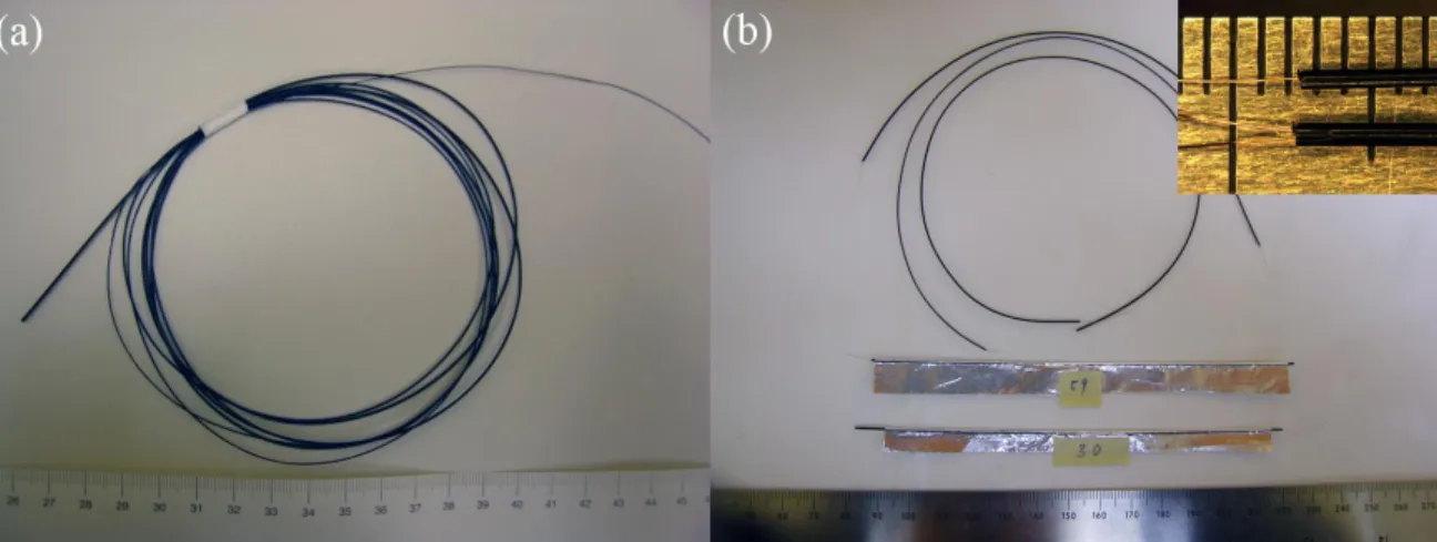
Fig. 2-3 (a) Capacitor fiber fabricated from the preform shown in Fig. 2-2(c). The fiber features a central 100m-thick copper wire, as well as an exposed conductive plastic electrode on the fiber surface. (b) To perform electrical characterization of the fibers, embedded copper wire is used as the first electrical probe, while the second electrical probe is an aluminum foil wrapped around the fiber conductive surface. The inset is an enlarged view of the fibers with single and double copper wire electrodes.
2.2 Electrical properties of the soft capacitor fibers
2.2.1 Setup for characterization of the isolated capacitor fiber
To characterize electrical properties of our capacitor fibers we used a measurement circuit presented in Fig. 2-4, where the fiber capacitor is connected to a function generator (GFG-8216A, Good Will Instrument Co., Ltd) through the reference resistor Rref = 480 k. The
function generator provides a sinusoidal signal of tunable frequency =[0.3Hz-3MHz]. An oscilloscope (GDS-1022, Good Will Instrument Co., Ltd) measures the input voltage VCh1 () on
channel 1 and the output voltage over the reference resistor VCh2 () on channel 2. A 10X probe
(GTP-060A-4, Good Will Instrument Co., Ltd) was used to acquire the experimental data. The voltage produced by the function generator is fixed and in the whole frequency range of interest equals to VCh1 = 2V. In our experiments we measured both the amplitudes and the phase
difference between channels 1 and 2. Due to high resistivity of our fibers and also to fit the experimental data at higher frequencies (>1kHz), we have also to take into account the effective impedances of an oscilloscope.
In this section we present the properties of fiber capacitance and resistance as a function of various fiber geometrical parameters. Most of the measurements presented in this section were performed on fibers featuring a single copper electrode in their cores, while the second electrode is formed by the plastic conductive layer on the fiber surface (see Fig. 2-2(c)). The fiber was co-drawn with a 100 m-thick copper wire in its center. In the preform, both conductive layers are 75 m thick, while the two insulating layers are made of 86 m thick LDPE films.
To characterize capacitance fibers we used embedded copper wire as the first electrical probe, while the second electrical probe was made by wrapping aluminum foil around a part or the whole of the fiber (Fig. 2-3).
Fig. 2-4 Schematic of the measurement setup
2.2.2 RC ladder network model of a soft capacitor fiber fully covered with a
foil probe
The high resistivity of the conductive composite films endows the capacitor fiber with a distributed response. Particularly the fiber electrical properties can be well described by a RC ladder circuit. First, we consider the case when the fiber outer electrode is fully covered with a highly conductive foil probe. In this case, the problem becomes two dimensional (no longitudinal currents) and an RC ladder circuit presented in Fig. 2-5 describes transverse currents in the capacitor crossection.
In Fig. 2-5 a schematic of the ladder model is presented where Rt corresponds to the
transverse resistance of a single conductive film spiralling from the fiber core towards its surface. The value of the transverse resistance can then be approximated as:
t v c R d W L (2.1)
where ρv is the volume resistivity of the conductive films, L is the length of the fiber, W and dc
denote respectively the width and thickness of the conductive electrodes wrapped in the fiber crossection (see Fig. 2-2). To measure transverse resistance one has to ensure that there are no longitudinal (along the fiber length) currents in the fiber. Practically, to deduce transverse resistance one covers the outer fiber electrode (high resistance electrode) with a metallic foil, and then measures fiber AC response by applying the voltage between the inner copper electrode and the outer metallic foil.
For the longitudinal currents, fiber resistance will be: l v c L R Wd (2.2)
which for longer samples (L W ) is much higher than the transverse resistance.
To measure the longitudinal resistance one has to ensure that there are no transverse (perpendicular to the fiber length) currents in the fiber. Practically, it is difficult to measure the longitudinal resistance directly. In principle, if the electrode length (fiber length) is much longer than the net width of a conductive electrode wrapped in the fiber crossection, longitudinal resistance can be deduced from the AC measurement where high resistance outer electrode of a fiber is grounded on one end, while the inner high resistance electrode of the fiber is connected to a voltage supply at the other end. Note that the low resistance copper electrode has to be removed from the fiber for this measurement and DC measurements aren’t possible as in the described configuration fiber acts as a capacitor. Clearly, when connecting to a fiber using a continuous probe (like foil) along the whole fiber length, fiber resistance will be dominated by its transverse component.
Another fundamental parameter that determines fiber performance is the fiber capacitance denoted as C in schematics Fig. 2-5. As thicknesses of the dielectric and conductive layers in the
fiber are hundred times smaller than the fiber diameter, fiber capacitance can be well approximated using an expression for the equivalent parallel-plate capacitor:
0 2 i WL C d (2.3)
where is dielectric constant of the isolating films, 0 is permeability of the vacuum, di is
thickness of the rolled isolating films.
As shown in Fig. 2-5, i(x) and i’(x) denote the current flowing in the conductive film connected to the inner probe and outer probe respectively. V0 is the voltage difference between the inner probe and outer probe. We assume that the resistivity of the conductive film is a position-independant and frequency-indepent parameter. Appling Kirchhoff's Voltage Law (KVL) and Kirchhoff's Current Law (KCL) to the ladder circuit leads to the following equations:
' '
0 0 ( ) x t t x W R di x R i l dl i l dl V j C x W d W W
(2.4) and
'
di x di x (2.5)With boundary conditions
0 '
i i W and i W'
0 (2.6),equations (2.4), (2.5) and (2.6) can be solved analytically, and yields the following expressions for the effective transversal capacitance and effective transversal series resistance:
1
· F t C R Im f B (2.7),
2 t F t R R R Re f B (2.8), where
1 cosh
; 2 sinh t B f B B j R C B B Note at low frequencies, i.e. B→0, equations (2.7) and (2.8) reduce to the frequency-independent values as follows:
2 ,
3
F F t
C C R R (2.9)
2.2.3 Frequency dependent response of the capacitor fibers
As predicted by equations (2.7) and (2.8), effective capacitance and effective resistance of the capacitor fibers are dependent on the operational frequency, with limiting values at low frequencies given by (2.9). In this section we present results of experimental studies of the frequency dependent response of the capacitor fibers. To interpret correctly the measured response VCh2 () of the electric circuit it is important to take into the consideration the complex
impedance of the oscilloscope and the electric probe used in the characterization. This is mainly due to the relatively large resistance of our fibers. One also has to be aware that conductive films used in the fiber fabrication can show significant frequency-dependence of their electrical properties. For example it has been reported [74] that near the percolation threshold the resistivity of CB/polymer films decreases with increasing frequency. To find the effective circuit parameters of an oscilloscope we first measured the response of a known resistor having a similar resistance as that of a fiber (~477 k). We noted that complex impedance of the measuring circuit (oscilloscope) becomes important only at frequencies higher than 100 kHz. We then studied frequency response of the conductive film, and found that its resistivity is frequency independent below 300 kHz. Therefore, in all the experiments that followed we have operating frequencies lower than 100 kHz.
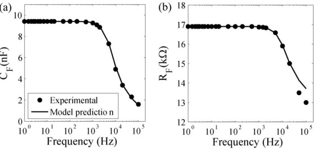
In Fig. 2-6 we present experimentally measured frequency dependent fiber resistance and capacitance of a fiber fully covered with a foil probe and with diameter of 0.93 mm and length of 137mm. At low frequencies both CF and RF are virtually constants, while they decrease at
and can be well explained by the RC ladder network model with a characteristic response frequency of 1/(RtC)~4 kHz. We can also see that equations (2.7) and (2.8) provide very good
predictions of the experimental data by assuming C=9.4 nF and Rt=26 kin the model.
Fig. 2-6 Comparison of experimental data and model predictions of frequency responses of a fiber capacitor. (a) Effective capacitance vs. frequency. (b) Effective resistance vs. frequency.
2.2.4 Effect of the capacitor fiber length
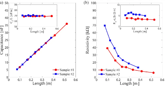
In order to study dependence of the fiber properties as a function of the fiber length, we have used two fiber samples of different length that were drawn from the same preform. Sample #1 and sample #2 had outer diameters of 920-980 m and 720-760 m respectively. Both samples were drawn from the same preform at speeds around 100 mm/min at 180℃. The two samples were then cut into sections of different lengths ranging between 10 cm and 60 cm, and then wrapped with an aluminum foil with 100% coverage ratio. The experiments were conducted at low frequencies (<1 kHz), so that effective capacitance and resistance can be considered as constant. In Fig. 2-7(a) we present measured fiber capacitance as a function of fiber length and observe a clear linear dependence. From this data we see that for all the fibers the capacitance per unit length is around 69 nF/m (inset in the Fig. 2-7(a)), which is very close to the value of 69.5 nF/m measured for the capacitance of the fiber preform. This finding is easy to rationalise from equations (2.3) and (2.9). As W/di is constant during drawing (because of the largely
homologous drawing), hence, CF/L should be the same for any fiber produced from the same
preform, regardless of the fiber size. The reason why our fibers can obtain large capacitance is because the value of W/di is much larger than that of a coaxial cable with one capacitive layer. In
contrast, fiber resistance decreases inversely proportional to the fiber length. In fact, it is rather the product RF·L which is approximately constant, as shown in the inset of Fig. 2-7(b). Equations
(2.1) and (2.9) indicate that if ρv is constant RF·L should also be a constant because W/dc is the
same for fibers drawn from the same preform. However, we also find that the thinner fiber shows a larger value of RF·L. This diameter dependency is implied in the volume resistivity ρv in
equation (2.1). It is reported that the resistivity of CB/polymer composites increase as the material is stretched, and the value is proportional to the elongation ratio in logarithm scale [75], [76]. Thus we observed that the thinner fiber has a larger RF·L value.
Fig. 2-7 Dependence of the (a) fiber capacitance and (b) fiber resistivity on fiber length. Red and blue data sets correspond to the two fiber samples of different diameters drawn from the same preform. Insets: dependence of the (a) fiber capacitance per unit length CF/L and (b) fiber resistivity factor RF·L on the fiber length.