Science Arts & Métiers (SAM)
is an open access repository that collects the work of Arts et Métiers Institute of
Technology researchers and makes it freely available over the web where possible.
This is an author-deposited version published in: https://sam.ensam.eu Handle ID: .http://hdl.handle.net/10985/18940
To cite this version :
Damien SUBIT, Felix MÖHLER, Bengt PIPKORN - Biofidelity Corridors for Sternum Kinematics in Low-Speed Side Impacts - Trafc Injury Prevention - Vol. 16, n°Suppl 2, p.S168–S175 - 2015
Any correspondence concerning this service should be sent to the repository Administrator : archiveouverte@ensam.eu
Biofidelity
Corridors for Sternum Kinematics in Low-Speed
Side
Impacts
DAMIEN SUBIT1,2, FELIX M ¨OHLER1,andBENGT PIPKORN3
1Ecole Nationale Sup´erieure d’Arts et M´etiers, LBM/Institut de Biomecanique Humaine Georges Charpak, Paris, France 2University of Virginia, Center for Applied Biomechanics, Charlottesville, Virginia
3Autoliv Research, V˚arg˚arda, Sweden
Objective: Field data show that side impact car crashes have become responsible for a greater proportion of the fatal crashes compared to frontal crashes, which suggests that the protection gained in frontal impact has not been matched in side impact. One of the reasons is the lack of understanding of the torso injury mechanisms in side impact. In particular, the deformation of the rib cage and how it affects the mechanical loading of the individual ribs have yet to be established. Therefore, the objective of this study was to characterize the ribcage deformation in side impacts by describing the kinematics of the sternum relative to the spine.
Methods: The 3D kinematics of the 1st and of the 5th or 6th thoracic vertebrae and of the sternum were obtained for three Post Mortem Human Subjects (PMHS) impacted laterally by a rigid wall traveling at 15 km/h. The experimental data were processed to express the kinematics of the sternum relative to the spine throughout the impact event. Methods were developed to interpolate the kinematics of the vertebrae for which experimental data were not available.
Results: The kinematics of the sternocostal junction for ribs 1 to 6 as well as the orientation of the sternum were expressed in the vertebra coordinate systems defined for each upper thoracic vertebra (T1 to T6). Corridors were designed for the motion of the sternum relative to each vertebra. In the experiments, the sternum moved upward for all rib levels (1 to 6), and away from the spine with an amplitude that increased with the decreasing rib level (from rib 1 to rib 6). None of the differences observed in the kinematics could be correlated to the occurrence of rib fractures.
Conclusions: This study provides both qualitative and quantitative information for the ribcage skeletal kinematics in side impact. This data set provides the information required to better evaluate computational models of the thorax for side impact simulations. The corridors developed in this study provide new biofidelity targets for the impact response of the ribcage. This study contributes to augmenting the state of knowledge of the human chest deformation in side impact to better characterize the rib fracture mechanisms. Keywords: side impact, kinematics, interpolation, vertebra orientation and position, biofidelity corridors
Introduction
Field data show that side impact car crashes are responsi-ble for a greater proportion of the fatal crashes compared to frontal crashes: while the ratio of side-to-frontal impacts for all multiple-vehicle crashes accidents is 43%, the same ratio for fatal accidents only is 51.6% (U.S. Department of Transporta-tion 2012). This shows that side impacts are responsible for a greater proportion of fatal crashes, but for a lesser proportion of all crashes. The challenge in side impact events is the pres-ence of parallel load paths due to the skeletal connections in
Associate Editor Joel Stitzel oversaw the review of this article. Address correspondence to Damien Subit, Ecole Nationale Sup´erieure d’Arts et M´etiers, LBM/Institut de Biomecanique Humaine Georges Charpak, 151 bd de l’H ˆopital 75013 Paris, France. E-mail: damien.subit@ensam.eu
Color versions of one or more of the figures in the article can be found online at www.tandfonline.com/gcpi.
the shoulder and ribcage (Compigne et al. 2004), and to the interaction between the arm and the ribcage (Kemper et al. 2008; Lessley et al. 2010). In particular, attempts were made to identify how the arm position affected the response of the impacted subject and the injury outcomes (Cesari et al. 1981; Kemper et al. 2008), and the link between shoulder dislocation and the occurrence of subsequent rib fractures (Lessley et al. 2010; Donlon et al. 2015). These studies were all based on ex-perimental work that involved post-mortem human subjects (PMHS), and provided valuable insight about injury mecha-nisms in side impacts. Although the study in Kemper et al. (2008) included non-injurious and injurious tests, the number of parameters such as the impact velocity and the position of the struck arm that could be varied was limited because of the risk of creating injuries as a result of repeated tests. There is a need to further investigate the deformation of the ribcage in side impact and the kinematics of the bony segments involved in the impact response of the body (ribcage, scapula, clavicle, arm, soft tissues). Such a study cannot be performed based on experiments because of the limited number of tests that can be
performed on a single PMHS, and it calls for a computational approach where a single human body model (HBM) can be subjected to a large parametric analysis without suffering any degradation between impacts.
Prior to running such a computational study, the biofidelity of the ribcage impact response in side impact needs to be eval-uated. The deformation of the ribcage (i.e. how the sternum moves relative to the spine) is likely an important factor in the estimation of the load and strain distribution in the ribs, as it is the result of both the loading caused by the interaction of the arm and the ribcage, and the overall dynamic response of the ribcage.. However, the data currently available to perform the biofidelity assessment of the ribcage itself with this level of details is missing: the data currently used to evaluate the biofidelity of a human surrogate’s ribcage include the medial-lateral half chest deflection (Kuppa et al. 2003; Kemper et al. 2008), chestband deflection (Pintar et al. 1997; Lessley et al. 2010), and force-deflection corridor (Shaw et al. 2006). Addi-tionally, tests with up to six single axis strain gages per rib were performed (Trosseille et al. 2008; Kemper et al. 2008; Lessley et al. 2010; Leport et al. 2011) to characterize the overall de-formation of the chest. However, while uniaxial strain gages provide information about the local deformation and the frac-ture timing, they do not provide insight about the overall de-formation of the individual ribs, such as tension, lateral and antero-posterior bending, and torsion. Unfortunately, none of these physical parameters (chest deflection, strain in the ribs) can be used to evaluate the complex deformation of the ribcage in side impact, and a description of the ribcage skeletal kinematics is needed.
The development of advanced methods for 3D kinematics measurement during PMHS tests has allowed researchers to describe the PMHS impact response in greater detail. A recent study by Donlon et al. (2015) provides a new data set that could be used to further describe the ribcage kinematics in side impact: 3D kinematic animations (3DKA) from side impact tests performed with PMHS were created by combining the 3D kinematics data of specific bones recorded by a marker-tracking system with the 3D reconstruction of these bones’ geometry from medical images. In particular, the trajectory of several vertebrae and of the sternum was reported in Donlon et al. (2015). Therefore, the goal of the current study was to provide biofidelity assessment targets for the ribcage skeletal kinematics in low-speed side impacts with a rigid wall.
Method
and Materials
Approach Developed in This Study
Donlon et al. (2015) published the 3DKA for three tests where male PMHS were impacted by a rigid wall traveling at 15 km/h. Each subject was installed in a rigid seat and held in position by a system of tethers that were released a few milliseconds prior to the impact (Lessley et al. 2010). The subjects (S1, S2 and S3, Appendix A1, see online supplement) were equipped with retroreflective markers connected to se-lected bones (spine, sternum, pelvis) that could be tracked during the entire impact event by the Vicon motion capture system. Arrays of four retroreflective markers typically affixed
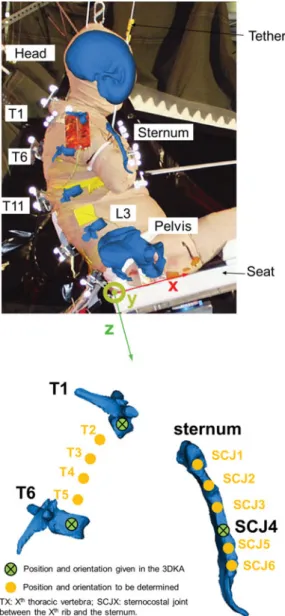
to the corner of a 75 × 75 mm square aluminum plate were rigidly connected to the selected bones. The kinematics of the bones themselves were obtained by applying the rigid body dynamic equations to the measured markers kinematics. The transfer matrix that described the position of the retroreflec-tive markers in the bone coordinate system was determined based on CT images where both the locations of bone land-marks and of the markers could be measured. In the 3DKA (Figure 1) the upper ribcage is represented by two vertebrae in the thoracic spine (T1 and T6 for S1 and S3, T1 and T5 for S2) and the sternum (Figure 2). To ease the presentation of the methods, T6 will be used in the following text to refer to either T5 (S2) or T6 (S1 and S3). Information about the PMHS is provided in Appendix A1.
The size of the marker plates was optimized to ensure accu-rate acquisition of the markers 3D trajectory with the Vicon system, while minimizing the risk of interaction with the sur-rounding structures: it was therefore not possible to acquire the kinematics of every vertebra because of the risk of interac-tion between the marker arrays connected to adjacent verte-brae. Because of this experimental constraint, the kinematics of the spine could be acquired only partially, and therefore an interpolation scheme was developed and used to estimate the trajectory and orientation of the non-instrumented thoracic vertebrae located between T1 and T6.
In the current study, the motion of the sternum relative to the thoracic spine (referred to as SRM: sternum relative mo-tion) was estimated for each rib level by determining the trans-lation of the sternocostal junction (SCJ) of the corresponding rib and the rotation of the sternum relative to the vertebral body where the rib’s costotransverse joint was located. The methodology included the following steps:
• Interpolation of the position and orientation of the ver-tebrae that are not included in the 3DKA, in the global coordinate system (GCS) and defined based on the seat geometry (Figure 2) that is fixed throughout the impact event,
• Determination of the position of the sternocostal joint (SCJ) at the lateral aspect of the impacted side of the ster-num for ribs 1 to 6, and of their trajectory during the impact event, in GCS,
• Definition of the vertebra coordinate system (VCS) for the thoracic vertebrae 1 to 6,
• Transformation of the SCJ coordinates and sternum orien-tation in VCS, for the corresponding rib level,
• Determination of response corridors for the translation of the SCJ and orientation of the sternum in each VCS.
Interpolation of the Position and Orientation of the Vertebrae As the cadaver data are only available for certain vertebrae (T1 and T6), the position and orientation of the missing vertebrae were interpolated to determine the kinematics of the poste-rior rib ends: because of the difference in the subject position between the CT bed (supine) and the test apparatus (seated), the relative positions of the T2 to T5 vertebrae could not be determined from the CT images. The vertebra coordinate system used in Donlon et al. (2015) was also used in this study.
Fig. 1. Overview of the 3DKA dataset (S1). The 3D kinematics and geometry of selected bones (head, T1, T6, T11, pelvis, ster-num) are provided to be used for visualization in the OpenSim software platform.
The origin of VCS was the midpoint of the center of the su-perior and inferior endplates, and the z-axis passed through the center of each endplate, pointing down. The y-axis direc-tion was given by the line passing through the left and right pedicles, positive to the right. The x-axis was orthogonal to the y- and z-axes, positive forward (Appendix A2, see online supplement).
The position of the vertebrae was interpolated using the Hobby interpolation algorithm (Hobby 1986) to create 3D Bezier curves: the origin of the T1 VCS and the T6 VCS were used as control points, and the z-axes of the VCS were used
Fig. 2. Left: Overlay of the 3DKA at time 0 and picture of S1 (lateral view from the struck side). The seat coordinate system that is used to define the global frame is shown. Right: Known bone position and orientations for the 3DKA, and position and orientation to be determined (shown for S1).
to define the tangent to the 3D Bezier curves in these con-trol points. Next, the geometry of the computational model THUMS (Total Human Model for Safety, version 1.4) was used to determine the position of the origin of the vertebrae located between T1 and T6, by computing the normalized curvilinear abscissa (length along the spine between T1 and each vertebra’s origin divided by the total length between T1 and T6). The vertebrae normalized curvilinear abscissae were then used to estimate the position of the vertebrae for S1, S2 and S3, based on the specific length between T1 and T6 (or T5 for S2).
Next, the orientation of these vertebrae was estimated. The rotation matrix between T1 and T6 coordinate systems (for S1 and S3, between T1 and T5 for S2), RT1,T6, was decomposed
as the product of five matrices: RT1,T6= RT1,T2× RT2,T3×
power of RT1,T6, where the power was the normalized
curvi-linear abscissawi= LLTi TiT1T6+1, i= 1..5:
RTi,Ti+1= RwT1,T6i , i = 1..5 (1)
As a consequence of the definition given in Eq. (1), the matrices RTi,Ti+1have all the mathematical properties intrinsic to rotation matrices. Finally, the rotation angles around the three global axes (GCS) were extracted from these matrices by expressing the RTi,Ti+1matrices in GCS (Eq. (2)).
RTi+1,GCS= RTTi,Ti+1× RTi,GCS (2)
The rotation matrices were decomposed into the Tait-Bryan angles that are sometimes referred to as Euler angles i.e. yaw (z-rotation), pitch (y-rotation) and roll (x-rotation) relative to GCS. RT1,GCSand RT6,GCSwere obtained directly from the 3DKA.
Evaluation of the Interpolation Methods
The interpolation methods were evaluated using simulations of the rigid wall impact performed with THUMS. THUMS was impacted in a similar fashion as the PMHS: a rigid wall impacted the right side of THUMS with a constant veloc-ity of 4.3 m/s (15 km/h). The evaluation happened in three steps. First, the thoracic spine overall kinematics predicted by THUMS and measured for the PMHS were compared to con-firm THUMS capability to predict the spine kinematics similar to that documented for the PMHS. Second, the actual position and orientation of the T1 to T6 vertebrae in THUMS were extracted every millisecond from the simulation output file (between time 0 that defined the time of first contact between the wall and the subject, and 130 milliseconds which was after THUMS lost contact with the impacting wall). Third, the posi-tion and orientaposi-tion of the T2 to T5 vertebrae in THUMS were calculated using the interpolation methods described above. The mean difference and maximum difference between the actual values for the position and orientation, and the inter-polated values, for all the vertebra levels, were calculated. Trajectory of the Sternocostal Joints in VCS
The sternum coordinate system in the 3DKA has its origin at the midpoint of the SCJ of the bilateral 4th ribs. The SCJ for ribs 1, 2, 3, 5 and 6 were located on the sternum 3D model pro-vided in the 3DKA. The sternum was considered rigid (Sandoz et al. 2013), and equations for rigid body kinematics were used to determine the trajectory of all the SCJs from the trajectory of the sternum origin and the sternum orientation. Next, the trajectory of each SCJ and the orientation of the sternum were expressed in the VCS of the corresponding vertebra.
Development of Response Corridors
Corridors were developed for each rib level to characterize the translation of the SCJ and orientation of the sternum in VCS: the upper and lower bounds were defined as the mean response
for the three PMHS plus-or-minus one standard deviation at each time step.
Results
Evaluation of the Interpolation Method
The kinematics of the T1, T5/T6, and T11 were qualitatively similar for THUMS and the PMHS (Appendix A3, see online supplement). In particular, THUMS kinematics was similar to S1’s kinematics, with the thoracic spine going up during the interaction between the subject and the wall (posterior view). In the sagittal plane, although the displacement of THUMS thoracic spine was less compared to that of the PMHS, its overall shape was preserved. This result indicates that the re-sponse of THUMS thoracic spine is realistic compared to that of the PMHS, in particular the deformation of the spine.
The accuracy of the interpolation methods was estimated between time 0 (time of first contact between the wall and THUMS) and 130 ms by calculating the mean difference be-tween the actual position of the vertebrae and the position es-timated by interpolation (Figure 3 and Table 1). For the orien-tation, the difference between the actual and predicted angles was expressed in terms of Euler angles, i.e. yaw (z-rotation), pitch (y-rotation) and roll (x-rotation) rotations obtained by decomposing the rotation matrix RVCS,GCSfor the T2 to T5
vertebrae (Table 1).
PMHS Responses and Corridors
Displacement and orientation corridors were developed for each rib level, and the PMHS traces were overlaid to show the inter-subject variability (see Figure 4 and Figure 5 for a sample of the data, and Appendix 4, see online supplement). The corridors are based on the results obtained for S1, S2 and S3 for the vertebrae T1 to T5, and only on S1 and S3 for T6, as the T6 trajectory was not available for S2 (the T5 trajectory was measured instead). At certain time steps, the standard deviation was 0 because the individual curves obtained for S1, S2, and S3 intersected. It is important to note that SRM is provided in each vertebra coordinate system which is not fixed in the seat coordinate system (global). Furthermore, the rotation corridors must be seen as ‘sequential’: the rotation about the y-axis (pitch) depends on the rotation about the z-axis (yaw), and the rotation about the x-axis (roll) depends on the rotation about the y-axis (pitch), and therefore about the z-axis (yaw) also. The coordinates of the SCJ for each PMHS are provided in appendix A5, the initial orientations (yaw, pitch, roll) of the VCS are provided in Appendix A6 (see online supplement), and the individual PMHS responses are provided in Appendix A7 (see online supplement).
Discussion
Interpolation of the Vertebrae Position and Orientation The position and orientation of the upper thoracic ribcage were obtained by interpolation of the experimental results, as
Fig. 3. Exact and interpolated positions of the upper thoracic vertebrae (subject 1).
Table 1. Mean and maximum errors for the position and orien-tation of the THUMS vertebrae expressed in the seat coordinate system
Difference in positions [mm]
Difference in orientation [degrees]
x y z yaw pitch roll
Across all rib levels
Mean 2.18 0.15 1.07 0.4 3.37 1.25 Maximum 3.94 0.43 1.96 1.63 5.56 3.35 Per rib level T2 1.74 0.32 0.66 0.84 4.9 2.5
T3 3.05 0.43 1.32 1.63 5.56 3.35 T4 3.94 0.37 1.96 1.24 4.91 3.11 T5 1.84 0.25 1.11 0.69 0.81 2.01
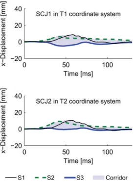
Fig. 4. Displacement of the SCJ in the x-direction in VCS for the 1st and 2nd rib levels. See Appendix 4 (online supplement) for the complete set of results.
Donlon et al.’s (2015) data set did not include this information for all the vertebrae. The actual curvilinear abscissa of the vertebrae along the spine was also required to perform the interpolation, but this data was not available in Donlon et al.’s (2015) dataset. In fact, this data could not be found for seated subjects, as cadavers are routinely imaged in prone or supine position, and the spine curvature is known to change between
Fig. 5. Yaw angles for the sternum relative the T1 and T2 coordi-nate systems. See Appendix 4 for the complete set of results.
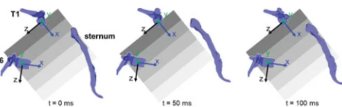
Fig. 6. Position and orientation of the sternum relative to the T1 vertebra (subject 1), and time history plots. In (a), the shaded areas have the same size and are in the same position relative to T1 in the three plots.
the lying and seated positions (Nyquist and Patrick 1976). Therefore, the use of a vehicle occupant finite element model such as THUMS was seen as the only possibility to estimate the relative position between the upper thoracic vertebrae. Had the PMHS tests not been already performed, additional 3D measurements could have been taken on each seated PMHS to document the position of each vertebra. The reliability of the interpolation method was further estimated by accounting for the variation in the shape of the spine throughout the impact by using the results of the rigid wall impact simulated with THUMS. These simulations provided a data set where both the exact and interpolated position and orientation of the T2 to T5 vertebrae are available throughout time: the THUMS simulation results were thus suitable to assess the performance of the interpolation method. Although the question of the biofidelity of THUMS in side impact has only been partially assessed (Pipkorn et al. 2014), the use of a computational model was the only way to access the kinematics data for the whole upper thoracic spine that was required to evaluate the interpolation scheme.
The method developed to interpolate the orientation of the vertebrae proved to be effective at providing good results, while being straightforward to apply. The weightswiobtained with
THUMS were found to be valid at every time step, and were applied to the PMHS interpolated spine, which is equivalent to assuming that the THUMS and PMHS upper thoracic spine
are homothetic. Furthermore, the “distribution of rotation” along the spine was supposed to be linear – in other words the power for the rotation matrices was equal to wi. To improve
the interpolation results, a more complex function may be needed and could be obtained from an optimization scheme using the THUMS data.
Finally, the curvature of the spine was supposed to be given by the z-axis of the T1 and T5 (or T6) vertebra (direction or-thogonal to the vertebrae endplates). This approach is known to have limitations, as 3D reconstruction of the spine were shown to be more accurate when a statistical model of the spine is used (Humbert et al. 2009), but the 3DKA did not provide enough information about the spine geometry to estimate the geometric descriptors required to perform this reconstruction.
Sternum Trajectory in VCS
The SCJ at each rib level was found to follow a complex tra-jectory, which was mostly a combined upward (-z direction) and forward (+x direction) motion with respect to the vertebra (Figure 6 and Appendix A4, see online supplement). While the z-motion was nearly independent of the rib level, the ampli-tude of the x-motion increased with decreasing vertebra level (from T1 to T6). The rotation about the VCS y-axis however was nearly independent on the rib level. Complex time-history signals were obtained for the rotations about the VCS x- and z-axis, in particular for T1, T2 and T3 (lateral flexion and torsion of the spine). These rotations may be caused by the contact between the wall and the arm (Figure 2): the interaction of the arm and the ribcage for various arm positions was shown to have a considerable effect on the ribcage deformation and in-jury outcome (Kemper et al. 2008). The arm interaction with the ribcage would also greatly affect the motion of the sternum and the deformation of the ribs. The kinematic corridors for SRM developed in this study indicate that the sternum moved and rotated about the x, y and z axis, which is not shown by the contour information typically collected with chestbands from which lateral or antero-posterior deflections are calculated (Lessley et al. 2010; Kuppa and Eppinger 1998; Kuppa et al. 2003). Chestbands capture the contribution of several ribs, as they measure the contour of the ribcage in a transverse plane at a certain level (lateral rib 6 in Lessley et al. 2010), and there-fore the comparison of the chestband to the SRM information is not straightforward (Appendix A8, see online supplement).
Correlation Between the Documented Kinematics and the Injuries
The injury outcome varied greatly between PMHS: S1 had 16 rib fractures and a disruption of the struck shoulder, while S2 and S3 had no injury. S1 and S3 both had complex rotations of the sternum in the T1 coordinate system (positive lateral flexion from 20 to 40 ms, and negative lateral flexion after 40 ms), and S1 and S2 were both subjected to about 30 mm of maximum displacement of the sternum in the negative z-direction in VCS, which indicates that overall the sternum moved upward and closer to the spine, but only S1 had in-juries. The three PMHS included in the side rigid wall impact
(Lessley et al. 2010) were instrumented with uniaxial strain gages glued onto the lateral side of the cortical shell on rib 4 (lateral), 5 (anterior and lateral), 6 (anterior), and 10 (anterior) on the struck side. Rib fractures were reported for S1 on rib 2 (4 fractures), rib 3 (3 fractures), rib 4 (3 fractures), rib 5 (3 fractures), rib 6 (1 fracture) and rib 7 (1 fracture) for the struck side, and on rib 2 (1 fracture) for the contralateral side. The rib fractures that could be detected based on the strain data (frac-tures on ribs 4, 5 and 6) occurred between 24.7 and 30.4 ms, and compressive strains were recorded, (between 0.285 and 1.264%). The z-displacement of the sternum in the T4, T5 and T6 coordinate systems (Appendix A7, Figure A7-3 to 6, see online supplement) shows a change in slope between 25 and 30 ms, which corresponds to the time observed experimentally. Interestingly, such a change is not seen for the higher rib lev-els (1 to 3), although rib fractures were reported; furthermore similar changes in the z-displacement were observed for S2 (at around 30 ms, all levels, Figures A7-7 to 11) and for S3 (at around 40 ms, all levels, Figures A7-12 to 17), although no rib fractures were reported for S2 and S3. At this point, it is unclear whether the changes in slope are interpolation arte-facts that lead to the propagation of certain features of the T1 and T5/T6 response curves to the interpolated vertebrae, or the consequence of the loading point on the ribcage moving towards the posterior aspect of the ribcage throughout the im-pact because of the rotation of the subject away from the wall.
Injury Mechanism for the Ribs in Side Impact
The corridors developed in this study (Figures 4 and 5) provide a characterization of the sternum motion relative to the spine. An unexpected result of the current study is the large upward motion of the sternum relative to the spine that is consis-tent across subjects. Previous research by Duprey et al. (2010) showed that the rotational stiffness of the costo-vertebral joint for the cranial-caudal and ventral-dorsal directions were 3 and 5 times greater than for torsion around the cervical rib axis. Although the coordinate system used in Duprey et al.’s is different from that used in the current study, the motion of the sternum along the VCS z-axis would mostly be opposed by the torsion rotational stiffness (rotation about the cervical axis). This joint direction was reported as the most compliant, which is consistent with the z-displacement of the sternum being greater than the displacement in the x and y directions (Figure 4). This indicates that there is little torsion along the length of the rib due to cranial/caudal displacement of the sternum. On the contrary, the increase in the antero-posterior distance of the rib cord (defined as the increase of distance between the SCJ and the corresponding VCS) would mostly lead to a rotation in the ventral-dorsal direction. The costo-vertebral junction (CVJ) is the stiffest in this direction, and therefore the x-displacement in VCS leads most likely to the ‘straightening’ of the ribs (bending against its radius of curva-ture). This phenomenon is consistent with the arm interaction with the ribcage in side impact reported in previous studies (Kemper et al. 2008). However, it is unclear whether the arm pushing against the ribcage generates the entire straightening of the rib, or if other phenomena could be involved, such as the
inertia of the rib cage due to the heterogeneous distribution of the mass within the rib cage. Another important aspect of the arm/rib cage interaction is the actual contact area between the arm and the ribcage that varies during the impact and that is difficult to measure in the experiments.
The sternum kinematics documented in the current study was measured from three elderly male PMHS. It is fair to assume that the costal cartilages in the tested ribcages were certainly markedly calcified as a result of aging (McCormick 1980). This suggests that the results reported in the current study would be different for younger subjects, as a softer costal cartilage would lead to a different sternum kinematics, simi-lar to what Murakami et al. (2006) showed for frontal belt loading. Also, the size and shape of the ribcage are likely to influence the sternum kinematics, and therefore the sternum kinematics could be sex and age dependent. One effect of ag-ing is the stiffenag-ing of the costal cartilage that results in the increase coupling between the anterior end of the rib and the sternum. This could lead in different strain distribution in the rib, and potentially to different fracture locations as a result of aging. This hypothesis cannot be validated with the data presented in the current study, but computational mod-eling could contribute to identify the influence of aging on the ribcage skeletal kinematics.
Limitations
A simple method was used to develop the corridors, which led to corridors being reduced to a single point for some times. Furthermore, for the rotations, the yaw, pitch and roll angles are not independent, as rotations are not commutative. This is a common limitation in the representation of rotation, and no better solution is available.
Besides, the corridors were developed based on the follow-ing assumptions:
• The sternum was assumed to be rigid,
• Three PMHS were included in the study, and they were only male and exposed to low-energy impacts,
• The arms of the PMHS were cut mid-humerus, and the effect of their orientation on the impact response was not evaluated,
• The ribs were defined as the rib bone itself, the costal car-tilage, and the costo-vertebral joint. This assumption may not be a serious limitation as the PMHS were elderly sub-jects and therefore the costal cartilage was greatly calcified, • The actual orientation of the costal cartilage relative to the sternum was not accounted for, and therefore only the change in the sternum orientation was provided in the cur-rent study,
• For the lower ribs (rib 6, and also rib 5 in some cases), the costal cartilage merges with that of the adjacent ribs located below, and it is therefore difficult to identify the actual mechanical loading applied to the ribs.
Although detailed injury reports and strain data were doc-umented in Lessley et al. (2010) tests, the effect of injuries on the reported kinematics could not be quantified, as no obvi-ous differences were identified between S1 on the one hand,
and S2 and S3 on the other hand. Finally, the interpolation technique was evaluated based on a simulation with a compu-tational model for only one posture; however, a recent study by Poulard et al. (2014) showed that the subject initial posture was an important predictor of the subject response to side impact.
Conclusions
A kinematics analysis of experimental tests was performed to describe the kinematics of the ribcage in side impact, defined as the sternum relative motion to the spine. Novel interpolation methods were developed to estimate the vertebrae trajectory and orientation that could not be obtained during the ex-periments. The trajectory and orientation of the sternum was obtained in each of the T1 to T6 vertebrae coordinate system. It was shown that the sternum moved upward relative to the vertebrae for all rib levels (1 to 6), and away from the verte-brae with an amplitude that increased with the decreasing rib level (from rib 1 to rib 6). No differences observed in the kine-matics could be correlated to the occurrence of rib fractures. This study provides a characterization of the ribcage skeletal response in side impact that will allow safety researchers to better evaluate computational models of the thorax: this step will contribute to improve the biofidelity of these models at a very detailed level to ultimately use these models to analyze strain distribution in the ribs and better predict the occurrence of rib fractures and their location. Further analysis of PMHS kinematics in side impact for higher energy impact and other impact conditions is required to better describe the injury mechanisms: because of the complex interactions that take place between several body structures during a side impact (arm, scapula, clavicle, ribcage), and the limited data that can be obtained during a single experiment, computational work is expected to complement the analysis of PMHS experiments and contribute to the elucidation of the injury phenomena specific to side impact.
Funding
The analysis performed in this study has been funded by and carried out in association with SAFER - Vehicle and Traffic Safety Centre at Chalmers University of Technology, Swe-den. D. Subit thanks European Union for its financial sup-port through the Marie Curie International Incoming Fellow-ship (FP7-PEOPLE-2013-IIF, project BioAge # 622905). F. M ¨ohler gratefully acknowledges the financial support from the Franco-German University through the Franco-German double degree program between ENSAM and KIT. The views expressed in this article are those of the authors and do not necessarily represent the views of the funding bodies.
Supplemental
Material
Supplemental data for this article can be accessed on the pub-lisher’s website.
References
Cesari D, Ramet M, Bloch J. Influence of arm position on thoracic injuries in side impact. In Proceedings from the 25th Stapp Car
Crash Conference - Society of Automotive Engineers, Warrendale, PA.
1981;270–297.
Compigne S, Caire Y, Quesnel T, Verriest JP. Non-injurious and in-jurious impact response of the human shoulder: Three-dimensional analysis of kinematics and determination of injury threshold. Stapp
Car Crash J. 2004;48:89–124.
Donlon JP, Poulard D, Riley P, Subit D. Understanding how pre-impact posture can affect injury outcome in side pre-impact sled tests using a new tool for animation of cadaver kinematics. J Biomech. 2015;48(3):529–33.
Duprey S, Subit D, Guillemot H, Kent RW. Biomechanical properties of the costovertebral joint. Med Eng & Phys. 2010;32(2):222–227. Hobby JD. Smooth, easy to compute interpolating splines. Discrete
Com-put Geom. 1986;1(1):123–140.
Humbert L, De Guise JA, Aubert B, Godbout B, Skalli W. 3D recon-struction of the spine from biplanar X-rays using parametric models based on transversal and longitudinal inferences. Med Eng & Phy. 2009;31(6):681–687.
Kemper AR, McNally C, Kennedy EA, Manoogian SJ, Duma SM. The influence of arm position on thoracic response in side impacts. Stapp
Car Crash Journal. 2008;52:379–420.
Kuppa S, Eppinger R. Development of an improved thoracic injury cri-terion. Stapp Car Crash Conference Proceedings. 1998. Paper 983153. Kuppa S, Eppinger R, McKoy F, et al. Development of side impact tho-racic injury criteria and their application to the modified ES-2 dummy with rib extensions (ES-2re). Stapp Car Crash J. 2003;47:189–210. Leport T, Baudrit P, Potier P, et al. Study of rib fracture mechanisms
based on the rib strain profiles in side and forward oblique impact.
Stapp Car Crash J. 2011;55:199–250.
Lessley D, Shaw G, Parent D, et al. Whole-body response to pure lateral impact, Stapp Car Crash J. 2010;54:289–336.
McCormick WF. Mineralization of the costal cartilages as an indicator of age: Preliminary observations. J Forensic Sci. 1980;25:736–741. Murakami D, Kobayashi S, Torigaki T, Kent R. Finite element analysis
of hard and soft tissue contributions to thoracic response: sensitivity analysis of fluctuations in boundary conditions. Stapp Car Crash J. 2006;50:169–189.
Nyquist G, Patrick L. Lumbar and pelvic orientation of the vehicle seated volunteers. In Proceedings of the 20tht Stapp Car Crash Conference. 1976;667–696.
Pintar FA, Yoganandan N, Hines MH, et al. Chestband analysis of human tolerance to side impact. In Proceedings of the 41thStapp Car Crash Conference. 1997;63–74.
Pipkorn B, Subit D, Donlon JP, Sunnev˚ang C. A computational biome-chanical analysis to assess the trade-off between chest deflection and spine translation in side impact. Traffic Inj Prev. 2014;15(Suppl 1):S231–7
Poulard D, Subit D, Donlon JP, et al. The contribution of pre-impact spine posture on human body model response in whole-body side impact. Stapp Car Crash J. 2014;58:385–422.
Sandoz B, Badina A, Laporte S, et al. Quantitative geometric analysis of rib, costal cartilage and sternum from childhood to teenagehood.
Med Biol Eng Comput. 2013;51(9):971–9.
Shaw J, Herriott R, McFadden J, Donnelly B, Bolte J. Oblique and lateral impact response of the PMHS thorax. Stapp Car Crash J. 2006;50:147–167.
Trosseille X, Baudrit P, Leport T, Vallancien G. Rib cage strain pat-tern as a function of chest loading configuration. Stapp Car Crash J. 2008;52:205–31.
U.S. Department of Transportation, National Highway Traffic Safety Administration (NHTSA). Traffic safety facts - A compilation of mo-tor vehicle crash data from the Fatality Analysis Reporting System and the General Estimates System. 2012. Available at: http://www-nrd.nhtsa.dot.gov/CMSWeb/index.aspx.