Science Arts & Métiers (SAM)
is an open access repository that collects the work of Arts et Métiers Institute of Technology researchers and makes it freely available over the web where possible.
This is an author-deposited version published in: https://sam.ensam.eu Handle ID: .http://hdl.handle.net/10985/13514
To cite this version :
N. SPITZ, Nicolas CONIGLIO, Mohamed EL MANSORI, Alex MONTAGNE, Sabeur MEZGHANI -Quantitative and representative adherence assessment of coated and uncoated
concrete-formwork - Surface and Coatings Technology - Vol. 352, p.247-256 - 2018
Any correspondence concerning this service should be sent to the repository Administrator : [email protected]
1
Quantitative and representative adherence assessment of coated and uncoated concrete-formwork
N. Spitz1, N. Coniglio1, M. El Mansori1, A. Montagne2, S. Mezghani3
1Arts et Métiers ParisTech d’Aix-en-Provence, Laboratory of Mechanics, Surface and Materials Processing (MSMP-EA7350), 2 cours des Arts et Métiers, 13617 Aix-en-Provence – France 2
Arts et Métiers ParisTech de Lille, Laboratory of Mechanics, Surface and Materials Processing (MSMP-EA7350), 8 Boulevard Louis XIV, 59800 Lille – France
3
Arts et Métiers ParisTech de Châlons-en-Champagne, Laboratory of Mechanics, Surface and Materials Processing (MSMP-EA7350), Rue Saint-Dominique, 51000 Châlons-en-Champagne – France
Abstract
Nowadays buildings construction is performed by pouring concrete into molds called formworks that are usually prefabricated metallic modules. Defects such as stripping may possibly form during the removal of the formwork if the interfacial bonding between the concrete and the formwork is high. Making use of a new pull-off tensile test designed in our laboratory, a correlation has been established between the formwork surface functional signatures and its adherence propensity to concrete. The originality of this near-to-surface test was to characterize the concrete-to-formwork adherence by measuring the required force to pull the concrete from the formwork surface. The design of the test coupon was validated by finite element analysis that proves the small deformation of the tested formwork specimen under the tensile loading and the homogeneity of the applied tensile stress at the interface. The interfacial bonding to concrete has been compared between bare and coated formwork. Both metallic and polymer coatings have been studied. The analyses of the pull-off test results enabled us to understand the bonding mechanisms at the concrete-coating interfaces. The pull-off tensile test was proven capable of ranking formwork coatings according to their adherence to concrete.
Keywords:
Concrete, skin formwork functionality, Formwork-concrete interface, roughness measurement, adherence
2
1. INTRODUCTION
The construction industry uses formworks as temporary molds into which concrete is poured. The adherence of concrete to formworks generates several aesthetic defaults (e.g. concrete breaking) on the concrete walls when removing the formwork. The formworks are rigid structures with a skin material that can be either wood, plywood, bare steel or a steel coated with a polymer film [1]. Metallic formworks, such as steel, stainless steel, and aluminum with protective epoxy varnish, are used for simple planar forms. The bare steel formwork skins are commonly used on construction sites for their sturdiness and their long-life span. Wood formworks are used for more complex forms and during cold weather but require a specific varnish to avoid excessive water absorption. Very complex forms are usually poured between polymeric formworks.
A boundary layer is usually formed at the concrete-formwork interface during curing. This limit layer is an aqueous solution only composed of the fine particles coming from the cement and the filler. The concrete adherence to the skin in this layer is due to mechanical anchoring and physicochemical interactions [2]–[7]. Today, organic and inorganic lubricants are used before each concrete pouring as release agents, but these products are usually not environment-friendly, toxic, and are difficult to deposit uniformly on the skin [8]–[10]. The interfacial bonding depends partly on the water-cement ratio [11], [12], the polymer additives [6], [11], [13] and the filler substitutes [11]. The concrete adherence is partially avoided by modifying the skin surface through the condensation of a water layer [14], the application of a polymer coating [5], [15], or the spreading of release agents [4], [8], [9], [16] prior to concrete pouring. The lubricant family, i.e. vegetal or mineral [4], [16], the environment temperature [9] and the application mode [8] are also of major importance. Nevertheless, research aims today at developing a novel formwork that has a long-life span and does not require any superficial demolding agents.
Concrete adherence has been viewed in a great diversity of ways. Its occurrence on formworks has been defined in terms of mechanical anchoring [2]–[5], electrocapillary forces [2]–[4], [6] and chemical bonding through the Ca(OH)2 formation [5]–[7]. Arguing that large defects favor concrete trapping [2]–[5], it has been demonstrated that adherence will occur if the concrete accumulates into the hollows of the formworks to create a three-dimensional interface. Adherence is subsequently enhanced for rougher formwork surfaces, higher fluidity of the fresh concrete, concrete with smaller cement particles, and formwork vibrations during concrete pouring. Electrocapillary-based models [2]–[4], [6] have recognized that surface energy is also an important factor, but only in so far as it serves to accumulate a thin water layer at the interface during curing leading to interfacial tension modification by the presence of electrical charges, capillarity effect, and subsequently cohesion within the liquid and adhesive forces between the liquid and formwork. Arguing that formation of numerous chemical complexes permits a large build-up of bonds and a
3 greater likelihood to adhere [5]–[7], it has been demonstrated that adherence will occur if calcium chemical complexes are formed by reaction of the calcium hydroxides in the concrete with the metallic hydroxides at the formwork surface [7], [17]–[19]. Most of these models suffer from one common shortfall in that they fail to address how the interface is fractured. It is therefore difficult to predict if the interface will fracture before the concrete volume and subsequently hinder wall default formation.
Few works have investigated the effect of the formwork skin superficial characteristics on the concrete ability to adhere to the skin. The adherence is avoidable with a controlled skin roughness that is low enough to avoid mechanical anchoring and high enough to avoid capillary forces or with a controlled skin chemistry using a special galvanized superficial treatment. Despite these works, the topic of adherence as it applies to skin-concrete interactions remains a contentious subject, particularly with regard to identifying the skin superficial characteristics that would ideally avoid concrete adherence without lubricant spreading. No research work has been performed on the formwork skin design specifications in terms of superficial characteristics to avoid its adherence to the concrete.
Questions regarding the concrete adherence arise when developing new formwork designs. The adherence is troublesome when pouring concrete against sensitive skin materials of formworks. Adherence testing has been largely limited to evaluating full-scale conditions and micro-scale analyses. While full-scale testing on site is possible [5], it is costly in time and resources. On the opposite, nano-indentation characterizations [20] have been performed on adherent interfaces between substrates and concrete but their extrapolation to on-site conditions is limited. In-between, little tests have been performed on laboratory scales, such as steel bars pulled out a concrete block [21], [22], and are unfortunately focused on reinforced bars and are not applicable for formworks applications.
The present work investigates the effect of the functional signatures of the formwork surfaces on the concrete adherence. Using a newly developed pull-off testing, the concrete adherence was determined for different surfaces. A test procedure was specifically developed for the formwork applications. Surface energy and roughness were measured and correlated to the concrete-to-skin adherence. Interfacial adherence mechanisms are discussed.
2. BACKGROUND
1. Adherence mechanism
Some works focusing on the concrete formulations observed that the water-cement ratio [11], [12], the polymer additives [6], [11], [13] and the filler substitutes [11] modify the formwork-concrete interface. Other works on the formwork-concrete-skin interface observed that the adherence is
4 partially avoided by condensing a water layer on the skin [14], adding a polymer coating [5], [15], or applying release agents on the skin [4], [8], [9], [16] prior to concrete casting. In particular, the lubricant family, i.e. vegetal or mineral [4], [16], the environment temperature [9] and the application mode are of major importance [8]. Based on the review, concrete-formwork bonding strength can be reduced by: deposition of release agents, minimizing vibrations during pouring, roughness optimization to favor a Cassie-Baxter wetting regime, and stopping the electrical double layer formation.
The curing concrete organizes itself near the formwork surface in three layers [23], [24] that result from various inside (e.g. sedimentation, segregation, water permeation) and outside (e.g. formwork wall effect, mechanical vibrations) phenomena. The first 101-102 µm-thick layer present along the skin is the most important in regard to adherence issues. This layer is composed of the finest cement particles and water with additions of cement substituents and admixtures if present in the initial concrete mixture. Bonding induced by this layer may arise from mechanical anchoring, electrocapillary forces and chemical bonding through the Ca(OH)2 formation.
The skin surface may avoid adherence with a controlled roughness that is low enough to avoid mechanical anchoring [2], [3], [5], [6], [25]. The propensity of mechanical anchoring is high when the cement particles penetrate the surface hollows [26]. Thus, mechanical vibrations of the formwork during pouring enhances the cement particle penetration in the superficial asperities [5] leading to high bonding strength. Bonding is also lowered by the presence of a residual humidity film at the interface that hinders the penetration of concrete fines [2]–[4]. Subsequently, mechanical anchoring is lowered for formworks with controlled roughness and superficial hydrophobicity.
Electrocapillary forces develop at the concrete-formwork interface by the formation of a continuous thin water layer at the formwork skin surface. The induced concrete-formwork bond is stronger for smooth and impermeable skins such as steel formworks [2]–[4], [14]. Absorption of water at the formwork surface [2]–[4], such as for wood formworks, or hydrophobic surfaces [27] prevent the formation of the continuous interfacial water film and consequently the capillary forces. Chemical bonding may appear from chemical reactions between the formwork surface and the concrete components [5]–[7], [12], [17], [27], [28]. The calcium hydroxides in the concrete react with the metallic hydroxides to form calcium-based chemical complexes that chemically bond the formwork to the cement. Steel surfaces contain Fe2+ ions that react with the Ca2+, Al+ and OH- ions present in the concrete to form metallic hydroxides [5]–[7]. The amount of Ca(OH)2 increases with longer concrete curing durations [12] which lead to an increase in bonding strength from 0.19 to 0.49 MPa for curing durations from 1 to 3 days, respectively [5]. A hot-dip zinc coated formwork skin is particularly sensitive to strong bonding [22], [29] with the formation of calcium hydroxizincate ( ) ) [7], [17]–[19] that may possibly be avoided by addition of Al in the Zn coating
5 [7], [30]. Interestingly, even polymeric surfaces may have small chemical bonding [27], [28]. The formation of Ca(OH)2 at the concrete surface may be accompanied by the transfer of some polymeric particles from the formwork to the concrete [27].
2. Adherence testing
Concrete adherence testing to date has been largely limited to full-scale testing on formwork or laboratory-scale testing on reinforced steel bars. No laboratory scale testing device has been designed today for characterizing concrete adherence to a substrate in a representative manner of full-scale formwork use. Nevertheless, the results should be applicable to formwork designs. The concrete-to-substrate bonding strength has been quantified by pull-off, pull-out, and bending tests. These tests have been proven useful in providing insights for understanding interfacial bonding of concrete to metallic, ceramic, and polymeric surfaces. Comparison of different works may be limited because of the difference in the concrete chemistry.
Pull-off tests performed on concrete-to-steel interfaces revealed that the failure contained both cohesive and adhesive failure zones, where adhesive failure is favored for strong cohesive bonding [7]. Longer contact times between cement paste and substrate enhance bonding from 0.19 up to 0.49 MPa after 3 days of curing [5]. Increasing the surface roughness improves the mechanical anchoring leading to an increase in bonding strength from 0.03 to 0.52 MPa [7]. Nevertheless, care must be taken on the meaning of these stresses as capillary forces may induce high contact forces even though no concrete adhered to the substrate. Concrete adhered strongly to hot dip galvanized steels with a 0.23 MPa bonding strength, which drops to 0.01 MPa [7] with the addition of Al in the galvanized coating that reacts preferentially to Zn with ions OH-[Ca(OH)2] in alcaline-pH cement [30], [31]. In addition, polymers reduce the bonding strength [32], [33] down to 10-2 MPa [5]. Efficient additions to the polymeric surfaces for lowering the adherence propensity include silicone [27], [28], fluor-plastic and Bakelite [5]. These additions strongly increase the hydrophobicity of the coatings and avoid the adherence propensity.
Micrometer scale characterizations were performed by depth-sensing micro- and nano-indentations [12], [20], [34]. The interfacial transition zone (ITZ) exhibits a large variability in mechanical behavior due to the heterogeneous components present: steel, hydrated phases, and unhydrated cement [20]. A drastic drop in elastic modulus from 200 GPa in steel to 5.5-31.9 GPa in paste was observed along with high porosity and presence of weak phases in the ITZ [20]. Small-scale testing of the ITZ identified low mechanical properties of the Ca(OH)2-rich interfacial transition [34] and numerous large porosities [12], [20]. A sudden transition accompanied by an immediate change in properties between the steel and paste is recommended for lowering the bond strength between steel and cement [20]. Considering all these information from the open literature, a
6 representative new pull-off tensile test was designed to quantify the adherence of formwork skin to concrete during stripping.
3. EXPERIMENTAL
Experimental determination of concrete adherence to the formwork was performed by a home-made experimental device. The proposed adherence test is designed to fracture the concrete-to-formwork bonds by means of a tensile force applied perpendicular to the interface. Following the small bond strength expected for some interfaces, no preloading condition is presently selected.
1. Finite element analysis
A new pull-off test was designed specifically for investigating the adherence of concrete on formwork materials. Some specifications were required. The testing device weight with hardened concrete must be below 20 kg for easy manipulation. It must be customized for the Instron 1185 tensile machine equipped with a 100 kN cell force. The pull-off force must be perpendicular to the surface of the formwork specimen. Finally, the distortions during testing must be small to maintain a nearly-single tensile stress at the interface.
Geometrical models were created in a finite element modeling packing ABAQUS. Material properties of S235 structural steel and AA2007 aluminum alloy, which were applied to the formwork specimen and the test device respectively, are presented in Table 1. The 5 mm-thick formwork specimens with steel stiffeners and the concrete aluminum support had internal and external diameters of 250 and 330 mm respectively (Figure 1). The aluminum mold was designed to hold the fresh concrete during curing and tensile testing. Aluminum alloy was selected for lowering the weight of the testing device ). Quad node shell elements of mesh size 5 were used for the structural analysis. The displacements in the Z direction were smaller than 4·10-3 and 2·10-5 mm for the aluminum support and the formwork specimen with stiffeners, respectively. These small displacements suggest that the assumption of a tensile mode of stress at the concrete-to-formwork interface will be acceptable for the current pull-off test design.
Table 1: Material properties applied to the finite element simulation. S235 Structural Steel AA2007 Aluminum Alloy
Young’s modulus 210 Gpa Young’s modulus 72 Gpa Poisson’s ratio 0.28 Poisson’s ratio 0.33
7
Figure 1 Schematic of (a) aluminum test device and (b) formwork specimen with steel stiffeners.
2. Pull-off test
The 330 mm-diameter formwork specimen support was cut by C02 laser on a 1000 x 2000 x 5 mm laminated plates of steel. Stiffeners of 30 x 10 mm cross-sections were welded underneath with the MAG process. Test coupons were then fixed on the steel supports by either resistance-spot welding for metallic skins or gluing for polymeric coatings. Adherence propensity was studied by means of a newly developed pull-off test until the total debonding of concrete on the plates. The test involved the application of a tensile force, kept perpendicular to the interfacial surface using a spherical plain bearing (Figure 2). All adherence tests were carried out in a controlled environment of temperature and relative humidity. The pull-off test sequence consisted of the following steps: 1. Fix tested specimen on the support
2. Clamp tested specimen with aluminum support 3. Pour concrete into support
4. Leave sample without disturbance for 24 hours, ensuring complete concrete curing 5. Start tensile test with a displacement rate of 0.05 mm·s-1
6. Remove tested specimen for optical analysis Øext330 mm Øin250 mm h 40 mm h 30 mm Ø 330 mm h 35 mm
a)
b)
8
Figure 2 Overview of pull-off adherence test.
The pull-off force was measured by the concrete off the formwork, imitating the forces involved in the on-site formwork removal process. Force-displacement curves were acquired to measure the maximum force that can be sustained by the formwork-concrete interface. The experimental adherence stress σa is defined as the adherence force per surface area:
(1)
,where the adherence force is the peak separation force measured by the probe pulling test and the surface area is the contacting area between the probe and the concrete. The measurement of the adherence force was repeated three times.
After bond failure, the force cell supports the weight of the aluminum device filled with the concrete. Therefore, this weight is subtracted to the maximum measured force to estimate the tensile force required for the bond rupture. In addition, the specimen surface after testing was analyzed by imaging using the free software ImageJ. A brightness threshold is defined only on the 250 mm-diameter contact area to highlight the concrete left. Subsequently, the propensity of adherence is quantified by the percentage of surface covered by adhered concrete.
3. Materials
A single ordinary concrete has been used (Table 2: Composition of concreteTable 2). The paste volume of the concrete is 32 %. The water/binder ratio is 0.57. One 7 kg concrete batch is prepared for each test. The concrete was manually prepared according to the mixing procedure from the standard NF P 18-404 [35]. The workability of the concrete was checked using the Abrams cone method. The slump obtained for each mix was 13 ± 1 cm, i.e. consistency class of S3. During the
9 pouring concrete into the mold, this one was shaken by hand to improve the implementation of the concrete. The curing of concrete was 24h, namely the average time of curing on construction site.
Table 2: Composition of concrete. Components Quantity (kg.m-3) Cement CEM I 52,5 265 Limestone filler 88 Sand 0/4 792 Gravel 2/6 271 Gravel 6/16.5 734 Water 201
Four formwork surfaces were studied in this work: a mild steel skin, a zinc/aluminum alloy (Zn/Al) coating on a steel skin, a polytetrafluoroethylene (PTFE) coating and polymeric coating with an unknown composition. The mild steel formwork skins are commonly used on-site during concrete wall construction because of its good efficiencies but require lubrication for proper use. The Zn-based galvanized steels are rather used to enhance the bond between the reinforcement rebars and the concrete [36], [37]. However, some works [7], [19] showed Al added to the Zn coatings would hinder the chemical reaction between Ca and Zn and therefore would decrease the galvanized steel to concrete bond. Thus, the surfaces recover with a zinc/aluminum alloy could be used like formwork skin without lubrication layer.
The mild steel samples were cut from a 5 mm-thick laminated plate and the Zn/Al coating was deposited on 2 mm-thick steel plates. The PTFE coating is a coating put on ordinary formworks for lowering the concrete adherence. The fourth coating, known to be an efficient commercial solution, is tested but its composition was not provided and was thus analyzed by DSC, ATG, and FTIR.
4. Surface characterization
Surface signatures were characterized to understand the functionality of the formwork skins. Scanning electron microscopy (SEM) in conjunction with X-ray diffraction (XRD) were performed on mild and Zn/Al coated steel coupons. A nickel layer was deposited on the coupon surfaces to protect them from the deteriorations induced by the mechanical polishing. The coupons were immersed in
10 the Electroless Nickel Plating Solution at a temperature between 71°C and 82°C with a deposition rate of 10 µm.h-1. Cross sections were afterwards cut, ground, and mechanically polished using a 0.05 µm-diamond suspension. Morphological characterizations were performed with a scanning electron microscope JEOL JSM-7001F using secondary electrons for the surface topography and backscattered electrons for the chemical contrast (compo mode). Micrographs of metallic samples were obtained in high vacuum (≈ 10-4 Pa) with acceleration voltage between 10 and 15 kV at a 10 mm working distance for different magnifications. In addition with the micrographic observations by SEM, energy dispersive spectroscopy (EDS) was carried out using an Oxford Instruments X-max analyzer with a detection surface of 20 mm². EDS spectra were analyzed by means of the software INCA.
Following the SEM measurements, the crystallographic phases were determined using a Siemens D500 X-ray diffractometer. A chromium anode with a Cr-Kα wavelength λ = 0.22911 nm radiation and diffraction angles 2θ from 40° to 160° at 40 kV and 30 mA were used. A vanadium filter was added in diffractometer to absorb the Cr-Kβ radiation. The pics detection was performed according to 2θ diffraction angles through the Bragg's law.
For the polymer coatings, thermogravimetric analysis (TGA), differential scanning calorimetry (DSC) and Fourier Transform-Infrared (FT-IR) Spectroscopy were carried out. Thermograms were obtained using a TA Instruments TGA Q500 thermogravimetric analyzer heating the samples up to 900°C with a rate of 20 °C.min-1 under a 50 ml.min-1 nitrogen flowing. The DSC characterization was performed on a TA Instruments DSC Q10 calorimeter on samples heated at 10 °C.min-1 from - 80°C to 190 °C temperature range and under a 50 ml.min-1 flow rate of nitrogen. Weight fraction crystallinity (Xc) was determined by
⁄ where is the heat of fusion of the measured sample determined at endothermic melting peak and is the enthalpy of fusion of 100% crystalline material. The FT-IR analysis was realized on a Fisher FT-IR spectrometer from Perkin Elmer in transmission and ATR (Attenuated Total Reflection) modes. The sample was in contact with a diamond/ZnSe crystal. Four scans per mode were recorded over the range 4000–600 cm−1 with a spectral resolution of 4 cm−1.
Surface topography was measured using a white-light interferometry microscope (WLIM) VEECO NT3300 over a 4x4 mm² area. The surface was sampled at 2052 x 2052 points with a 1.9 µm step scale along X- and Y-directions. 10 analyses have been carried out for each material. The arithmetic mean height (Sa), the root mean square height (Sq), the developed interfacial area ratio (Sdr), the core void volume (Vvc) and the valley void volume (Vvv) were computed according to the ISO
11 25178-2 norm [38]. Vvc and Vvv are calculated from 10%-80% and 80%-100% of the bearing ratio respectively [39].
The principles of thermodynamic adhesion and surface energy have been applied with the aim of establishing relationships between the thermodynamic work of adhesion and the observed extent of adhesion of concrete to formwork materials. Surface energies were measured using the Morphoscan from Michalex Tribometrix by means of the sessile drop method according to the norm AFNOR EN 828 [40]. Drops were deposited in an environment of 22 ± 1 °C temperature and 54 ± 2 % relative humidity. Surfaces were cleaned using ultrasound and ethanol. Two liquids, deionized water and glycerol, were used with characteristics given in Table 3. A syringe of inside diameter of 4.6mm equipped with a needle of 0.8 mm outside diameter was used to deposit 5±1 µL droplets. The capillary length K (Table 3) is given by √ ⁄ [25] where is liquid superficial tension, liquid density, and g gravitational acceleration. The droplets have a radius in the 1.26±0.36 mm range, smaller than the capillary length, so that gravity is negligible. The static droplet shape on the sample’s surface was recorded as a 720x480 pixels image ten seconds after the drop was deposited. Advancing contact angles were measured to an accuracy of ±4° using the open source image processing program ImageJ. Ten droplets of each liquid were deposited at various locations on the surface of each sample to obtain an arithmetic medium value of the contact angles. Left and right angles were used to determine the reported surface energy.
Table 3: Surface tensions of liquids used [40]. Liquid Superficial Tension (mN·m-1) Dispersed Component (mN·m-1) Polar Component (mN·m-1) Density (kg·m-3) Capillary Length (m) Deionized water 72.80 21.80 51.00 1000 0.0027 Glycerol 63.40 37.00 26.40 1260 0.0023
The analysis is founded upon the Owens-Wendt model [41] for a perfectly flat homogeneous solid surface wetted by a liquid drop:
(2)
where and are the solid-vapor and liquid-vapor superficial tensions, respectively. Eq.2 is rewritten by implementing the polar (subscript P) and dispersed (subscript D) components of surface tensions and [40]:
)
√
√ √
12 where is the contact angle for a given liquid drop. Linear best-fitting of )
√ versus √
estimates the polar (slope) and dispersed (residue) components. The surface energy of the substrate is afterward calculated as the sum of the polar and dispersed components.
4. RESULTS
1. Surface layer analysis a. Metallic surfaces
Metallic surfaces were observed by SEM, EDS, and XRD. The surface of mild steel consisted of a non-uniform 10.9 µm-thick oxide layer (Figure 3a). Two sub-layers of 4.1 and 6.8 µm thick respectively were separated by a thin white region rich in nickel, which resulted from the diffusion of the nickel protective layer through the oxide top sub-layer during the Electroless Nickel Plating. This suggests a very porous top sub-layer and a discontinuity between the two sub-layers. The oxygen-on-iron contents ratios measured by EDS were 32 and 35 % for the bottom and top sub-layers, respectively, which are close to the theoretical ratios of 27.7% and 30.1% for Fe3O4 (magnetite) and α-Fe2O3 (hematite), respectively. XRD spectrum supports the presence of these crystalline phases with high intensity for α-Fe2O3 (JCPDS 33-0664) and Fe3O4 (JCPDS 87-2334) (Figure 3b). Since the α-Fe2O3 oxide has important lubricating properties while the harder Fe3O4 oxide has a good wear resistance [42]–[44], the presence of both oxides explain in part the good tribological property of the formwork skin surface. The porosity of the top oxide layer suggests that mechanical anchoring is the main mechanism for the concrete adherence.
13
(a)
(b)
Figure 3 Mild steel surface analyses by (a) SEM and (b) XRD.
The Zn/Al coated steel was studied to determinate the Al effect on the Zn-to-concrete bond. A coating contained 55% Al and 45% Zn were chosen. Observation of the Zn/Al coated steel substrates revealed a black layer underneath the concrete, indicating that chemical reactions occurred. When pouring concrete once more on this reacted layer, the concrete-coating boundary fractured through this black layer that detached from the steel to adhere to the solid concrete. SEM images revealed that the black layer formed and the material underneath this layer after its detachment is porous (Figure 4b and c). EDS analyses of these surfaces identified a reduction in the aluminum peak intensity at 1.487 keV energy after reaction of the Zn/Al coating with the concrete, suggesting a preferential reaction with the fresh concrete to form aluminum hydroxide Al(OH)3 rather than zinc hydroxide Zn(OH)2. Even though the aluminum reacted preferentially, the chemical components formed a strong chemical bonding that induced preferentially a cohesive failure.
The pH increase in alkaline environments leads to a large decrease of aluminum reduction potential and subsequently a greater mass loss by corrosion [30]. The preferential aluminum oxidation compared to the zinc in the concrete basic environment (pHconcrete = 13) could be explained to the Al(OH)3/Al(s) reduction potential ( ) ⁄ )) [45]) lower than the Zn(OH)2/Zn(s) reduction potential ( ) ⁄ )) [45]). The final product formed
14 by the reaction between concrete and aluminum will be calcium aluminate according to the following sequence of reactions:
) [30] (4)
) [30] (5) [31] (6)
According to Montgomery and Samarin [7], the addition of aluminum had hindered the reaction between zinc and the concrete and an adhesive rupture had been observed. In this work, opposite results were found. For galvanized steels, the addition of cerium or lanthanum in the zinc coating was demonstrated to delay the zinc dissolution in the concrete in developing zinc and rare-earth chemical compounds [19]. Unfortunately, the identification of the compounds in the black layer was unsuccessful by XRD because of the too-thin layer and the large background noise induced by the important porosity.
Figure 4 SEM imaging of (a) initial Zn/Al coating, (b) black porous layer after concrete reaction, and (c) underneath layer after dark layer removal.
b. Polymeric coatings
Optical observations by TGA, DSC and FTIR revealed 3 sub-layers (Figure 5). The 150 µm-thick top layer is the functional layer in contact with the concrete. The bottom layer is the adhesive layer to stick the coating on the steel formwork surface. In between is the coating wear indicator appearing when the top functional layer must be replaced.
15
Figure 5 Optical micrograph of the coating put on the formwork skin.
The DSC curve measured during heating an endothermic peak of fusion at 164°C with an enthalpy of fusion of was . The temperature and enthalpy of fusion suggest a 35% crystalline polypropylene (PP) when compared to the enthalpy of fusion of 100% crystalline PP (198 J/g) [46], [47]. Curves similar to the one for PP were also found by TGA analyses [46], with a huge mass loss from 350 to 500 °C with 12% residual mass in form of a powder containing the inorganic filler material.
ATR-FTIR and Transmission-FTIR characterizations showed intense IR bands near to 3000 cm-1 and between 1500-650 cm-1 in the ATR-FTIR spectrum of the sample (Figure 6) which correspond again to PP [48]. The additional absorption peaks comprise between 1750 and 1550 cm-1 may possibly be due to some anhydride groups (-C=O) [47]–[50], but the exact PP grafted anhydride was undetermined because of the shift of the peaks possibly induced by molecular structural modifications. The transmission-FTIR spectrum of the residual filler after TGA testing showed band wavenumbers of 3470 cm-1 attributed to –OH bonds and of 2083 and 1641 cm-1 attributed to H-O-H bonds of the PP matrix [51]. 1080 and 900 cm-1 bands were observed for the Al-O-H and Al-O bonds of boehmite AlOOH particles, respectively [52]. Therefore, the composition of the commercial coating was a composite material at PP-grafted-anhydride matrix with about 12-15% of alumina filler, in agreement with patent WO 2016/059193 A1.
16 The PTFE coating was chosen and studied for his chemical composition, therefore no chemical analysis was performed. However, the optical observations revealed a 130 µm-thick functional layer above the adhesive layer stuck on the formwork skin.
2. Formwork interface characterization a. Adherence propensity assessment
In this work, the interface between the formwork skins and the concrete was studied horizontally whereas on construction sites, the concrete is cured vertically into the molds. Therefore, the microstructure and the characteristics of concrete skins could vary according to the pouring mode even if the phenomena of concrete adherence are close in both cases. Nevertheless it is assumed in the present work that a non-adherent surface in horizontal pouring should not be adherent for vertical pouring conditions because concrete-steel bonding in horizontal pouring is greater than in vertical pouring .
Surface adherence has been investigated for different surface materials and quantified in terms of an adherence stress (MPa) and the leftover residue at the probe surface expressed as the percentage of concrete per unit surface area (%). The force of interfacial failure and the percentage of adhered concrete are plotted as a function of specimen material in Figure 7. The repeatability of the pull-off test results was examined for all test conditions. Performing the test three times for fixed conditions resulted in a large variation in adherence strength but demonstrated a good repeatability within less 10% for the percentage of concrete adhered. For each tested surface, the outliers values were rejected using the Grubbs Test [53]. The non-repeatability of the adherence force suggests that some suction effect occurred moreover to the interfacial bond strength. Indeed, the polymeric flat smooth surfaces revealed the highest adherence strengths but with no concrete adhered. Therefore, the percentage of adhered concrete is not dependent on adhesive strength.
The adherence strength of concrete to polymeric coating was significantly higher than for metallic coatings, despite a greater amount of concrete left over at the metallic surfaces. This suggests different failure mechanisms in the surface adherence. The failure of surface bonding is via one of three different mechanisms: cohesive failure, cohesive–adhesive failure, and adhesive failure. The relative magnitude of the sample-probe adherence force and the cohesion strength of the sample determine which mechanism dominates surface bonding failure. By examining the probe surfaces after separation, adhesive and cohesive–adhesive were the two main failure modes. The transition from adhesive to cohesive failure is reflected by the increase in residue amount that is when the interfacial adhesive bonding strength between formwork and concrete exceeds the cohesive strength of the concrete. Only PTFE and PP surfaces showed a clean surface separation.
17 The percentage of adhered concrete was a meaningful quantitative indicator of the adherence propensity of the concrete on the tested specimen material.
Figure 7 Adherence stress (column bars) and percentage of adhered concrete (plotted line) for different specimen materials.
b. Surface topography
Roughness parameters calculated according to the ISO 25178-2 norm [38] are summarized in Table 4. Sdr expresses the real contact area between the material and the concrete. Sa and Sq are associated to the ability of material to trap cement particles on the surface. Vvc and Vvv parameters correlate to the amount of cement particles after normal running-in wear and excessive wear, respectively, and subsequently the retention and entrapment properties of the surface. Figure 8 shows the percentage of concrete adhered against the formwork skins as a function of varied topographical parameters. Below a developed interfacial area ratio of about 1.9 % (Figure 8a), concrete doesn’t adhere on the substrate. Beyond this value, the developed area allows the mechanical adherence of concrete on the formwork skins. The polymeric coatings have developed areas smaller than metallic materials therefore the surfaces of polymers are smoother which explains the increase of adhesive strengths due to a strong suction effect. Concerning the Sa, Vvc and Vvv parameters, the trends are similar. The increase of Sa, Vvc or Vvv leads to the rise of percentage of pulled-out concrete apart from the PTFE coating (represented by the rightmost points in the Figure 8b, c and d). Indeed, the large size of hollows and the low rigidity of PTFE allow asperities to distort during the pull-off test, thus lowering the propensity of cohesive rupture of the concrete during mechanical debonding. 0 25 50 75 100 0.00 0.01 0.02 0.03 0.04 0.05 0.06 0.07
PP coating PTFE coating Mild steel Zn/Al coated steel
Co ncr e te adh er ed (%) Ad her ence s tr ess (MP a) Formwork skins
18
Table 4: Topographical parameters of formwork skins.
Materials Sdr (%) Sa (µm) Sq (µm) Vvc (µm3/µm2) Vvv (nm3/nm2) Mild Steel 2.4 ± 0.2 0.9 ± 0.1 1.1 ± 0.1 1.7 ± 0.1 145 ± 18 Zn/Al coated steel 4.3 ± 0.1 1.6 ± 0.2 2.0 ± 0.2 2.2 ± 0.3 242 ± 33 PP coating 1.5 ± 0.2 0.8 ± 0.1 1.0 ± 0.1 1.1 ± 0.2 109 ± 18 PTFE coating 1.3 ± 0.1 2.2 ± 0.3 2.8 ± 0.4 3.7 ± 0.7 254 ± 46
Figure 8: Adhered concrete percentage as a function of: a) Sdr, b) Sa, c) Vvc and d) Vvv.
c. Surface energy
The surface energies based on the Owens-Wendt approach [41] are summarized in Table 5. Statistical analysis showed that all the formwork surfaces had significantly different values of surface energy. As expected, the total surface energy is the lowest for polymeric coatings and highest for metallic surfaces. On average, the surface energy reported in this study for PTFE (12.0 mN·m-1) and PP (8.5 mN·m-1) are fairly low compared to values reported in literature for PTFE (from 18.6 to 23.9 mN·m-1 [54]) and PP (from 19.3 to 29.4 mN·m-1 [54]) but close to the one measured for commercial PTFE (8.9 mN·m-1 [55]). Differences may possibly arise from different additives, different empirical approaches used in the surface energy calculation, and different experimental conditions.
0 25 50 75 100 0 1 2 3 4 5 A d h e re d c o n cr e te ( % ) Sdr (%) 0 25 50 75 100 0 1 2 3 A d h e re d c o n cr e te ( % ) Sa (µm) 0 25 50 75 100 0 1 2 3 4 5 A d h e re d c o n cr e te ( % ) Vvc (µm3/µm2) 0 25 50 75 100 0 100 200 300 400 A d h e re d c o n cr e te ( % ) Vvv (nm3/nm2) a) b) c) d)
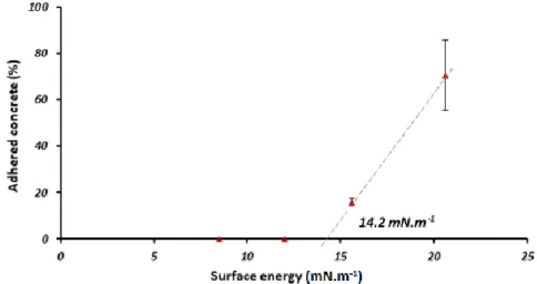
19 The surface energy is connected to the ability of material to interact with the cement paste. A surface with a high free energy will tend to attract more concrete. The surfaces with the lowest surface energy should have subsequently smaller work of adhesion of the concrete under the hypothesis that no chemical reaction occurred.
Figure 9 shows the percentage of concrete adhered against the formwork skins as a function of surface energy. Total surface energy and thermodynamic work of adhesion have been proven correlated [55] in agreement with Figure 9. The curve indicated a threshold surface energy of 14.2 mN·m-1 below which concrete has minimal surface adhesion with the formwork surface.
Table 5: Surface energies of materials. Materials Polar component
(mN·m-1)
Dispersive component (mN·m-1)
Total surface energy
(mN·m-1
)
Mild Steel 2.3 13.3 15.6
Zn/Al coated steel 9.5 11.1 20.6
PP coating 3.6 4.9 8.5
PTFE coating 1.8 10.2 12.0
20
5. DISCUSSION
Few works have been devoted in understanding the underlying mechanisms of the concrete-formwork interactions. Moreover, the comparison of literature data is difficult due to the various concrete compositions, water-to-cement ratios, and the concrete curing times. A normalized methodology is required to assemble the data. Nevertheless, common trends are observed. Identifying the underlying mechanisms of adhesion revealed some important parameters such as formwork material, surface energy, and roughness. Two mechanisms were identified for the concrete adherence on the specimens: mechanical anchoring (mild steel) and chemical reactions (Zn/Al coated steel). Consequently, PTFE and PP coatings did not have any adhered concrete because of their chemical inertia. Nevertheless, their smooth surface and hydrophobicity generated the formation of a water layer at the interface leading to a strong suction effect and high pull-off tensile force. These results are in agreement with the recommended avoidance of porous coatings and reactive calcium silicates-rich cements to hinder mechanical and chemical bonding at the formwork-concrete interface [20], [36].
The bond between steel formwork and concrete is generally caused by the propensity for water to adsorb onto the steel surface and interfacial effects at the steel/paste boundary. The resulting ITZ is generally rich in weak hydrated phases, such as Ca(OH)2, and exhibits lot of porosity due to a locally high water-to-cement ratio [12]. The mechanical properties of the ITZ decrease with heterogeneity, anisotropy, and porosity in microstructure [20]. The ITZ provides a bond which is both mechanical by embedding of concrete into the surface asperities and chemical/electrochemical through Ca(OH)2 formation.
Concrete adherence is induced by capillary forces, chemical reactions, and mechanical anchoring. Capillary forces are reduced by using hydrophobic and rough surfaces or by water-absorbing surfaces that avoid the water-rich first layer formation. Chemical reactions are particularly important with Zn-containing metals and negligible on polymers. Mechanical anchoring is reduced by limiting the surface roughness. Therefore, an ideal surface formwork design may be proposed that does not need lubricant to avoid concrete adherence. A non-adherent surface should ideally be a polymeric surface with a controlled roughness (Sdr < 1.9%). Nevertheless, the softness of these surfaces may possibly have a short lifetime regarding the abrasion induced by the concrete during pouring. Further works are required to identify a material that possesses both wear resistance and non-adherence properties. In order to confirm the assumptions made in the case of horizontally poured concrete, vertical pouring tests of the concrete may be carried out at the laboratory scale to reflect the operational conditions of a casting on site.
21
6. CONCLUSION
A new pull-off test and testing procedure has been developed for investigating interfaces between concrete and substrate at the laboratory scale. It allows the experimental determination of the adherence propensity by quantifying the percentage of concrete adhered to the surface. The functionality of surfaces in terms of adherence propensity to concrete has been compared. The properties of the formwork surface have significant influences on the concrete adhesion mechanism. The roughness measurements showed that metallic surfaces were rougher and could potentially trap more cement particles at the bottom of valleys. The polymer coatings possessed a surface energy twice as weak as the metallic skins, suggesting that the concrete chemical bonding to the polymer would be very low. The separation of concrete from the formwork was dominated by adhesion and cohesive failure mechanisms. The predominant mechanism depended on the nature of the formwork surface. While Zn/Al coated steel and mild steel showed predominantly cohesive failure with substantial amounts of concrete residue left on the probe surface, PTFE and PP revealed a clean surface separation. These adhesion propensities correlated with the surface energy of the formwork, providing a critical surface energy of the substrate above which cohesive failure occurred.
Although the new pull-off test is in some regards unique in its application of formwork adherence investigation, what is of particular important here is the expression of adherence propensity to the surface percentage of adhered concrete and its non-correlation with the adhesive force. Of particular importance is the possibility to use these data in the understanding of adherence mechanisms, allowing for future formwork material developments. As the failure mechanism depends on the balance between adhesive and cohesive strength, the threshold surface energy value may possibly differ regarding the nature of the concrete mixture and its mechanical properties.
ACKNOWLEDGEMENTS
The authors gratefully acknowledge the contribution of colleagues of Arts et Métiers ParisTech for their technical support and those received from the colleagues of the Procédés et Ingénerie en Mécanique et Materiaux laboratory (PIMM) for their formwork coating analyzes.
REFERENCES
[1] CimBéton, “T49 : La maîtrise esthétique des parements en béton,” Collect. Tech., 2005. [2] “L’adhérence du béton au coffrage,” Bull. du Cim., vol. 38, no. 8, 1970.
[3] “Décollement de la pellicule de ciment,” Bull. du Cim., vol. 37, no. 22, 1969.
[4] L. Libessart, P. De Caro, C. Djelal, and I. Dubois, “Correlation between adhesion energy of release agents on the formwork and demoulding performances,” Constr. Build. Mater., vol. 76, pp. 130–139, 2015.
22 [5] A. Mazkewitsch and A. Jaworski, “The adhesion between concrete and formwork,” Adhes.
between Polym. Concr. entre polymères béton, Springer US, pp. 67–72, 1986.
[6] J. Mlodecki, “Adhesion forces of polymer modified concrete and plain concrete to steel in moulds and in reinforced concretes,” Adhes. between Polym. Concr. entre polymères béton,
Springer US, pp. 55–63, 1986.
[7] D. G. Montgomery and A. Samarin, “Adhesion between concrete and treated or untreated flat metal surfaces,” MRS Proceedings, Cambridge Univ. Press, no. 114, p. 263, 1987.
[8] C. Djelal, A. Y. Vanhove, A. D. Chambellan, and A. P. Brisset, “Influence of the application method of release agents on thickness of mould oils,” Mater. Struct., 2009.
[9] G. Baty and R. Reynolds, “Release Agents-How they work,” Concr. Int., vol. 19, no. 9, pp. 52– 54, 1997.
[10] B. Courtois and P. Serre, “ED 6017 : Produits de démoulage des bétons : Composition, dangers, mesure de prévention,” INRS Paris, 2007.
[11] X. Fu and D. D. L. Chung, “Effects of water-cement ratio, curing age, silica fume, polymer admixtures, steel surface treatments, and corrosion on bond between concrete and steel reinforcing bars,” ACI Mater. J., vol. 95, pp. 725–734, 1998.
[12] A. T. Horne, I. G. Richardson, and R. M. D. Brydson, “Quantitative analysis of the microstructure of interfaces in steel reinforced concrete,” Cem. Concr. Res., vol. 37, pp. 1613– 1623, 2007.
[13] S. Bouharoun, Y. Vanhove, C. Djelal, P. De Caro, and I. Dubois, “Interactions between superplasticizer and release agents at the concrete/formwork interface,” Mater. Sci. Appl., vol. 3, pp. 384–389, 2012.
[14] N. Goudjil, Y. Vanhove, C. Djelal, and H. Kada, “Development of a new demoulding process based on concrete polarization,” 15th Int. Conf. Exp. Mech., pp. 1–16, 2012.
[15] M. K. Hurd, “High-performance plywoods For concrete forming,” Concr. Constr., p. 202, 1997. [16] L. Libessart, C. Djelal, and P. De Caro, “Influence of the type of release oil on steel formwork
corrosion and facing aesthetics,” Constr. Build. Mater., vol. 68, pp. 391–401, 2014. [17] A. D. Wilson, J. W. Nicholson, and H. J. Prosser, Surface Coatings-2. 1988.
[18] G.Arliguie and J.Grandet, “Etude par calorimetrie de l’hydratation du ciment Portland en presence de zinc,” Cem. Concr. Res., vol. 15, no. 5, pp. 825–832, 1985.
[19] M. Sánchez, M. C. Alonso, P. Cecílio, M. F. Montemor, and C. Andrade, “Electrochemical and analytical assessment of galvanized steel reinforcement pre-treated with Ce and La salts under alkaline media,” Cem. Concr. Compos., vol. 28, no. 3, pp. 256–266, 2006.
[20] P. G. Allison, R. D. Moser, C. A. Weiss, P. G. Malone, and S. W. Morefield, “Nanomechanical and chemical characterization of the interface between concrete, glass-ceramic bonding
23 enamel and reinforcing steel,” Constr. Build. Mater., 2012.
[21] X. Fu and D. D. L. Chung, “Linear correlation of bond strength and contact electrical resistivity between steel rebar and concrete,” Cem. Concr. Res., vol. 25, no. 7, pp. 1397–1402, 1995. [22] T. S. Phan, “Modélisation numérique de l’interface acier-béton : Application au
comportement des structures en béton renforcées par des aciers plats crantés,” Thèse Dr.
Univ. Paris Est, 2012.
[23] P. C. Kreijger, “The skin of concrete composition and properties,” Matériaux Constr., vol. 17, no. 4, pp. 275–283, 1984.
[24] S. J. Desouza, R. D. Hooton, and A. A. Bickley, “A field test for evaluating high performance concrete covercrete quality,” Can. J. Civ. Eng., vol. 25, pp. 551–556, 1998.
[25] P. G. De Gennes, F. Brochard-Wyart, and D. Quéré, Capillarity and wetting phenomena: drops,
bubbles, pearls, waves. Springer Science & Business Media, 2003.
[26] S. Bouharoun, “Friction behaviour of fresh concrete in the vicinity of formwork,” J. South
African Inst. Civ. Eng., vol. 55, no. 3, pp. 10–17, 2013.
[27] M. Horgnies, “Tribologie des bétons à ultra-haute performance - Propriétés de surface et revêtements de protection,” 2012.
[28] M. Horgnies, P. Willieme, and O. Gabet, “Influence of the surface properties of concrete on the adhesion of coating : Characterization of the interface by peel test and FT-IR spectroscopy,” Prog. Org. Coatings, vol. 72, no. 3, pp. 360–379, 2011.
[29] B. F. Tutikian, T. Hilgert, and J. J. Howland, “Adherence comparison of concrete with unprotected steel and hot galvanized steel,” Struct. Mater. J., vol. 7, pp. 314–320, 2014. [30] “La corrosion de l’aluminium par le mortier de ciment,” Bull. du Cim., vol. 34–35, no. 10, pp.
1–6, 1966.
[31] CSTB, CEBTP, VERITAS, CETEN_APAVE, SOCOTEC, NORISKO_Construction, SNFA, and QUALICONSULT, “Comportement de l’aluminium et ses alliages utilisés dans le bâtiment en contact avec le plâtre ou le ciment ainsi que d’autres matériaux,” Fiche Tech. N°40 - Indice A, pp. 1–2, 2008.
[32] A. B. Darwin and J. D. Scantlebury, “Retarding of corrosion processes on reinforcement bar in concrete with an FBE coating,” Cem. Concr. Compos., vol. 24, no. 1, pp. 73–78, 2002.
[33] J. Chang and W. Yeih, “The effects of particle shape on bond strength improvement of epoxy particle coating composites,” J. Mar. Sci. Technol., vol. 9, no. 2, pp. 153–160, 2001.
[34] W. Zhu and P. J. M. Bartos, “Application of depth-sensing microindentation testing to study of interfacial transition zone in reinforced concrete,” Cem. Concr. Res., vol. 30, pp. 1299–1304, 2000.
24 éprouvettes,” NF P 18-404, 1981.
[36] M. M. Jalili, S. Moradian, and D. Hosseinpour, “The use of inorganic conversion coatings to enhance the corrosion resistance of reinforcement and the bond strength at the rebar/concrete,” Constr. Build. Mater., vol. 23, no. 1, pp. 233–238, 2009.
[37] O. A. Kayyali and S. R. Yeomans, “Bond and slip of coated reinforcement concrete,” Constr.
Build. Mater., vol. 9, no. 4, pp. 219–226, 1995.
[38] AFNOR, “Spécification géométriquedes produits (GPS) - État de surface : surfacique - Partie 2 : termes, définitions et paramètres d’états de surface,” NF EN ISO 25178-2, 2012.
[39] AFNOR, “Spécification géométrique des produits (GPS) - État de surface : surfacique Partie 3 : Opérateurs de spécification,” NF EN ISO 25178-3.
[40] AFNOR, “Adhésifs - Mouillabilité - Détermination par mesurage de l’angle de contact et de l’énergie superficielle libre de la surface solide,” NF EN 828, 2013.
[41] D. K. Owens and R. C. Wendt, “Estimation of the surface free energy of polymers,” J. Appl.
Polym. Sci., vol. 13, no. 8, pp. 1741–1747, 1969.
[42] C. Vergne, C. Boher, R. Gras, and C. Levaillant, “Influence of oxides on friction in hot rolling: Experimental investigations and tribological modelling,” Wear, vol. 260, no. 9–10, pp. 957– 975, 2006.
[43] K. J. Chin, H. Zaidi, and T. Mathia, “Oxide film formation in magnetized sliding steel/steel contact—analysis of the contact stress field and film failure mode,” Wear, vol. 259, no. 1–6, pp. 477–481, 2005.
[44] X. Yu, Z. Jiang, D. Wei, C. Zhou, Q. Huang, and D. Yang, “Tribological properties of magnetite precipitate from oxide scale in hot-rolled microalloyed steel,” Wear, vol. 302, no. 1–2, pp. 1286–1294, 2013.
[45] P. Vanysek, “Electrochemical Series,” CRC Handb. Chem. Physics, 87th Ed., vol. 87, pp. 1–10, 1987.
[46] M. Sahli and J. C. Gelin, “Development of a feedstock formulation based on polypropylene for micro-powder soft embossing process of 316L stainless steel micro-channel part,” Int. J. Adv.
Manuf. Technol., vol. 69, no. 9–12, pp. 2139–2148, 2013.
[47] A. Oromiehie, H. Ebadi-Dehaghani, and S. Mirbagheri, “Chemical modification of polypropylene by maleic anhydride: melt grafting, characterization and mechanism,” Int. J.
Chem. Eng. Appl., vol. 5, no. 2, pp. 117–122, 2014.
[48] E. Andreassen, “Polypropylene,” vol. 2, no. August, 1999.
[49] H. H. S. Corporation, “DSC Measurement of Polypropylene,” no. 86, pp. 1–2, 2008.
[50] B. De Roover, M. Sclavons, V. Carlier, J. Devaux, R. Legras, and A. Momtaz, “Molecular characterization of maleic anhydride-functionalized polypropylene,” J. Polym. Sci. Part A
25
Polym. Chem., vol. 33, no. 5, pp. 829–842, 1995.
[51] C. Liu, K. Shih, Y. Gao, F. Li, and L. Wei, “Dechlorinating transformation of propachlor through nucleophilic substitution by dithionite on the surface of alumina,” J. Soils Sediments, vol. 12, no. 5, pp. 724–733, 2012.
[52] D. Y. Li, Y. S. Lin, Y. C. Li, D. L. Shieh, and J. L. Lin, “Synthesis of mesoporous pseudoboehmite and alumina templated with 1-hexadecyl-2,3-dimethyl-imidazolium chloride,” Microporous
Mesoporous Mater., vol. 108, no. 1–3, pp. 276–282, 2008.
[53] F. E. Grubbs, “Sample criteria for testing outlying observations,” Ann. Math. Stat., vol. 21, no. 1, pp. 27–58, 1950.
[54] M. Lewin, A. Mey-Marom, and R. Frank, “Surface free energies of polymeric materials, additives and minerals,” Polym. Adv. Technol., vol. 16, no. 6, pp. 429–441, 2005.
[55] E. L. Keijbets, J. Chen, E. Dickinson, and J. Vieira, “Surface energy investigation of chocolate adhesion to solid mould materials,” J. Food Eng., 2009.

![Table 3: Surface tensions of liquids used [40].](https://thumb-eu.123doks.com/thumbv2/123doknet/7378669.215347/12.892.135.759.732.843/table-surface-tensions-of-liquids-used.webp)