Science Arts & Métiers (SAM)
is an open access repository that collects the work of Arts et Métiers Institute of
Technology researchers and makes it freely available over the web where possible.
This is an author-deposited version published in: https://sam.ensam.eu Handle ID: .http://hdl.handle.net/10985/6817
To cite this version :
Fabien MEINGUET, Paul SANDULESCU, Bassel ASLAN, Li LU, Ngac Ky NGUYEN, Xavier KESTELYN, Eric SEMAIL - Signal-based Technique for Fault Detection and Isolation of Inverter Faults in Multi-phase Drives - In: IEEE International Conference on Power Electronics, Drives and Energy Systems 2012 (PEDES 2012), India, 2012-12-17 - IEEE International Conference on Power Electronics, Drives and Energy Systems 2012 (PEDES 2012) - 2012
Any correspondence concerning this service should be sent to the repository Administrator : archiveouverte@ensam.eu
Abstract—A method for fault detection and isolation is proposed and applied to inverter faults in multi-phase drives. An analysis of simulations in faulty conditions leads to the derivation of suitable fault indices. These are based on the unbalance of the phase currents and their instantaneous frequency. The method is applied to a five-phase permanent-magnet synchronous machine drive. Simulations and experiments validate the proposed method.
Keywords — AC machines, Condition monitoring, Multi-phase drives, Fault detection, Fault diagnosis, Inverters, Permanent magnet machines.
I. INTRODUCTION
Multi-phase machines are now used in various industrial applications and in transportation systems [1], mostly due to their advantages such as increased fault tolerance and power density [2], [3].
In a recent survey, statistics show that inverter parts are still the less reliable components, especially power semiconductors and gate drive systems [4]. Regarding multi-phase systems, the occurrence of faults is thus more likely and a proper detection system is required.
Besides hardware-based detection methods such as desaturation monitoring of the transistors and voltage measurements, many fault detection methods have been proposed for three-phase inverters [5]-[12]. These methods are generally based on the analysis of the phase currents and allow open-circuit faults to be detected, such as open-circuit switches or open-circuit phases.
In [5]-[8], analyses are conducted in the stator reference frame (αβ), through the derivative of the current-vector trajectory and of the derivative of its phase in [5], a pattern recognition with fuzzy logic in [6], a model-based observer which generates residuals in [7] and the derivative of the current-vector phase which is combined with an analysis of the polarity of the phase currents in [8].
Others methods are proposed in [9]-[12]. In [9], a simulation model of the faulty drive is used to train an artificial neural network. In [10], the authors focus the analysis on the normalized dc components of the phase currents and the number of samples close to zero current. In [11], a similar idea based on the normalized currents’ average absolute values is proposed. In [12], the instantaneous frequency of each phase current is estimated via phase-locked loops and deviations compared with the electrical frequency allow the faulty phase to be isolated.
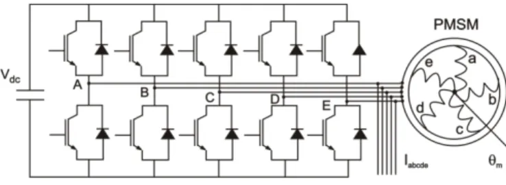
Fig. 1. Drive topology composed of a single energy source, a five-leg inverter and a five-phase star-connected PMSM.
It has to be noticed that all the aforementioned methods have been proposed for three-phase drives. In case a multi-phase drive is used, the latter accommodates the fault and the currents expressed in the stator reference frame are not much affected, making not effective all methods relying on these components. Therefore, methods based on the phase currents are more suitable [10]-[12].
There are a few works on fault detection and isolation (FDI) of multiphase drives [13]-[15]. In [13], the authors analyze the behavior of a five-phase machine with magnet faults. In [14], the behavior of a five-phase machine is analyzed with unbalanced stator windings. In [15], an open-circuit fault is detected by calculating the negative-sequence component on the fundamental αβ components, but the fault is not isolated. In this paper, a method for fault detection and isolation of inverter faults is investigated for multi-phase drives. The method is applied to a five-phase permanent-magnet synchronous machine (PMSM) drive. The faults under consideration are: open-phase faults and open-switch faults. First, an analysis highlights the main fault characteristics. Major differences compared with three-phase drives are evidenced. Then, relevant fault indices are proposed. These are based on the unbalance of the currents and their instantaneous frequency. Simulations and experimental results are presented throughout the paper.
II. SYSTEM DESCRIPTION
The topology under study is depicted in Fig. 1. The drive is composed of a single energy source, a five-leg inverter and a five-phase star-connected PMSM.
A. PMSM model
Neglecting the effects of saliency and magnetic saturation, the model of PMSMs is given by:
A Signal-based Technique for Fault Detection and
Isolation of Inverter Faults in Multi-phase Drives
Fabien Meinguet, Paul Sandulescu, Bassel Aslan, Li Lu, Ngac-Ky Nguyen, Xavier Kestelyn, and Eric Semail
Arts et Métiers ParisTech, L2EP, Lille, France Corresponding author: eric.semail@ensam.eu
(1)
where are the voltages at the machine terminals, the stator resistance, the phase currents, the inductance matrix and the electromotive force (emf) due to the permanent magnets.
The electrical equations (1) expressed in the synchronous reference frame are given by (2):
(2)
where is the electrical pulsation, , , , , , , , are the voltages, currents, emf and inductances associated with the fundamental component, whereas , , , , , , are the same quantities associated with the third-harmonic component.
The electromagnetic torque associated with the fundamental and third-harmonic components are given by (3) and (4) respectively, whereas the total electromagnetic torque is given by (5).
, (3)
, (4)
, ,
(5)
where is the number of pole pairs and , , , are the dq-axis emf for one mechanical radian per second [Vs rad-1].The parameters of the machine under study are given in Table I. It is assumed that the emf consists of fundamental- and third-harmonic components and that higher-order harmonics are negligible, although the ratios in magnitude compared with the fundamental are: k5 =12.4%, k7 = 5.1% and
k9 = 1.7%.
Table I. Machine parameters
Parameters Values 2.24 Ω 3.2 mH 0.9 mH 0.51 Vs rad-1 0 Vs rad-1 0.14 Vs rad-1 0 Vs rad-1 2
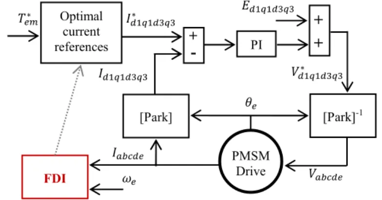
Fig. 2 General block diagram.
B. Control scheme
The block diagram of the control scheme is shown in Fig. 2. The torque reference is used to generate optimal current references [16]. A conventional proportional integral (PI) controller and emf compensation are used for the current control.
The phase currents and the electrical pulsation are the inputs of the fault detection and isolation (FDI) block, which will be described in section IV. It has to be noted that the diagnosis can be used to generate optimal current references next to the fault isolation, but this is beyond the scope of this paper.
III. ANALYSIS OF THE FAULT CONDITIONS
A. Control with an open-phase fault
Fig. 3 shows simulation and experimental results with an open-circuit fault (phase a) occurring at time t=0.05s. The test has been conducted with =200rad s-1, =1.15A and
=0.33A. Experimental tests consist in unplugging the phase connector. A comparison between the phase currents and the
dq currents shows a good concordance between simulations
and experiments (see Fig. 3(a), (b) (c) and (d)).
Before the fault occurrence, the five phase currents are balanced and are composed essentially of fundamental and third harmonic components. Upon the fault occurrence, the faulty-phase current is equal to zero, while the other phase currents increase to compensate for the loss of one phase. It can also be noticed that the healthy phase currents are no longer balanced following the fault occurrence.
In the synchronous reference frame, the currents are initially constant, while oscillations appear next to the fault occurrence.
B. Control with an open-switch fault
Fig. 4 shows simulation results with an open-switch fault (top switch of phase a) occurring at time t=0.05s. In this case, the faulty-phase current is equal to zero for a half-period (see Fig. 4(a)), while the other half-period is similar to a healthy half-period.
In the synchronous reference frame, oscillations appear next to the fault occurrence (see Fig. 4(b)). Compared with the open-circuit fault shown in Fig. 3, the pattern is slightly different since the dq currents alternate between constant values and oscillating values.
Optimal current references +
-
PI+
+
[Park]-1 [Park] PMSM Drive FDIFig. 3 Comparison of simulation and experimental results for an open-phase fault occurring at time t=0.05s (phase a).
Fig. 4. Simulation results for an open-switch fault occurring at time t=0.05s (top switch of phase a).
C. Comparison with three-phase drives
Regarding three-phase star-connected drives, a conventional analysis shows that, in case of open-circuit fault, the faulty-phase current is equal to zero during a part of the period, while both healthy currents are opposite in magnitude during this part of the period [5].
After the Concordia transformation, the αβ currents have a specific pattern for each possible fault: open-switch faults yield half-circles whereas open-phase faults yield a straight line. This pattern has been used in many works for the fault recognition.
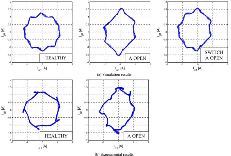
Regarding multi-phase machines, this analysis is not valid since the α1β1 components are not much affected by the faults, as presented in Fig. 5. The plots compare simulation
and experimental results (Fig. 5(a) and (b) respectively) for each state under study, i.e. the healthy state, the open-phase fault and open-switch fault.
The α1β1 current trajectory is a circle in the healthy state, possibly affected by harmonic components at a frequency equal to 10 . In case of fault, the trajectory changes, but not significantly compared with three-phase drives. Further, the pattern changes with the pulsation of the phase currents and the controllers gains. The analysis of the current trajectory in the α1β1 reference frame is therefore not appropriate for the fault recognition.
IV. FAULT DETECTION AND ISOLATION
A. Indices for Open-phase FDI
In the previous section, the fault characteristics have been analyzed.
Considering an open-circuit fault, an index can be based on the current unbalance. The faulty phase can be isolated when its current is close to zero. However, the condition “close to zero” can be misinterpreted in case the machine is operated at low current magnitudes. Therefore, the phase currents need to be compared with each other. At this step, the following fault index is proposed, for example for phase a (extension to other phases and n-phase systems is immediate):
(6)
where can be the peak or RMS value of the current in phase x ( , , , , ). Regarding the implementation, the method proposed in [17] is used. This method is based on a quadrature-signal generator. A 90°-shifted signal is associated to each current . The envelope of the signal is then obtained by calculating:
(7) 0 0.05 0.1 0.15 -1 0 1 2 Time [s] Idq [A] I d1 I q1 0 0.05 0.1 0.15 -2 -1 0 1 2 Time [s] Iab c d e [A] Ia Ib Ic Id Ie
(a) Phase currents (simulation results).
(b) dq currents (simulation results).
0 0.05 0.1 0.15 -2 -1 0 1 2 Time [s] Iabc de [A] Ia Ib Ic Id Ie 0 0.05 0.1 0.15 -2 -1 0 1 2 Time [s] Iabc d e [A] Ia Ib Ic Id Ie
(a) Phase currents (simulation results). (b) Phase currents (experimental results).
(c) dq currents (simulation results). (d) dq currents (experimental results).
0 0.05 0.1 0.15 -1 0 1 2 Time [s] Idq [A] Id1 I q1 0 0.05 0.1 0.15 -1 0 1 2 Time [s] Idq [A] I d1 I q1
Fig. 5. Fundamental currents expressed in the stator reference frame for various drive conditions. Comparison of waveforms obtained through simulations and experiments.
The advantages of (6) as fault index are: - in case of healthy operation,
and thus, from (6): 0 (and immediately 0);
- in case of open-phase fault in phase a, 0 and therefore, from (6), 1, without any dependency to load neither as to speed.
This is illustrated in Fig. 6(a) and (b), which show the fault indices for simulations (same as for Fig. 3) and experiments respectively, i.e. an open-circuit fault occurring at time t=0.05s (phase a). Before the fault occurrence, the fault indices are close to zero. Following the fault occurrence, the value of increases to 1. It has to be noticed that the value of other indices are not equal to zero. This is due to the unbalance of the healthy phase currents. The value of
0.5 is relatively high. This must be taken into account for the selection of the detection thresholds. Simulations and experiments are in good agreement, as shown in Fig. 6 (a) and
(b) respectively. Fig. 6 Magnitude indices in case of open-circuit fault occurring at time t=0.05s (phase a).
0 0.02 0.04 0.06 0.08 0.1 0.12 0.14 0.16 0.18 0.2 0 0.5 1 Time [s] F a ul t i n di c e s RMa RMb RMc R Md R Me 0 0.02 0.04 0.06 0.08 0.1 0.12 0.14 0.16 0.18 0.2 0 0.5 1 Time [s] Faul t i n di c e s R Ma R Mb R Mc RMd RMe (b) Experimental results. (a) Simulation results.
-2 -1 0 1 2 -2 -1.5 -1 -0.5 0 0.5 1 1.5 2 I α1 [A] I β1 [A ] -2 -1 0 1 2 -2 -1.5 -1 -0.5 0 0.5 1 1.5 2 I α1 [A] I β1 [A ] -2 -1 0 1 2 -2 -1.5 -1 -0.5 0 0.5 1 1.5 2 I α1 [A] I β1 [A ] HEALTHY
A OPEN
SWITCH
A OPEN
-2 -1 0 1 2 -2 -1.5 -1 -0.5 0 0.5 1 1.5 2 Iα1 [A] I β1 [A ] -2 -1 0 1 2 -2 -1.5 -1 -0.5 0 0.5 1 1.5 2 Iα1 [A] I1β [A ]HEALTHY
A OPEN
(a) Simulation results.
Fig. 7. Magnitude indices in case of open-switch fault occurring at time t=0.05s (top switch of phase a).
Fig. 8. Frequency indices in case of open-switch fault occurring at time t=0.05s (top switch of phase a).
B. Indices for Open-switch FDI
In section III, the characteristics of the open-switch fault have been evidenced. The system can be approximated as healthy during a half-period and as an open-circuit fault during the other half period. Hence, the magnitude indices will ideally take values which alternate between zero and one. This is illustrated in Fig. 7, where simulation results of an open-switch fault occurring at time t=0.05s are presented. The values of alternate between large and low values, although the values are never equal to zero and one. This is due to the filtering properties of the quadrature-signal generator [17].
Looking further at Fig. 6 and Fig. 7, it is difficult to find a decision criterion which is suitable for both faults and which allows the faults to be distinguished. Consequently, additional indices are proposed. These are based on the instantaneous frequency of each phase current. Benefits of the quadrature-signal generator are used through the addition of a synchronous reference frame phase-locked loop (PLL) [18]. The following fault index is proposed, for example for phase
a:
(8)
where is the instantaneous pulsation of the current in phase a. This index is equal to zero in healthy operation and equal to one in case of open circuit fault.
To avoid a drift of the PLL at low and zero current, the PLL is inhibited at low currents and the output is set by default at below a given threshold; therefore only deviations compared with the electrical pulsation are observed. This index is thus suitable for the isolation of open-switch fault.
Fig. 8 shows these frequency-based indices for the same simulation as for Fig. 7. is much affected by the fault as expected, while the other indices or not significantly affected.
C. Criterion for FDI
The ideal values of the indices for the faults under study are summarized in Fig. 9 and Fig. 10.
Fig. 9. Theoretical values of the fault indices in case of open-circuit fault occurring at time tdef.
Fig. 10. Theoretical values of the fault indices in case of open-switch fault occurring at time tdef.
Fig. 11. Indices used for fault detection and isolation and thresholds. For fault detection and isolation, a new index is proposed:
(9)
This new index is introduced to increase the robustness of the FDI scheme. An interesting property of is that the surface defined by versus time is a constant over one electrical period for both faults, as shown in Fig. 11 (S1=S2). Therefore, a relevant criterion indicating that a fault has occurred in phase x is given by:
(10)
where is a fault function associated with phase x, is a threshold defining a safety area, is the isolation threshold and is the time of the fault occurrence. Hence, considering an entire number of periods, the detection delay ∆ is theoretically given by:
0 0.02 0.04 0.06 0.08 0.1 0.12 0.14 0.16 0.18 0.2 0 0.5 1 Time [s] F a ul t i n di c e s RMa RMb RMc RMd RMe 1
0
t
deft
1
0
t
2
A OPEN
SWITCH A OPEN
S1
S2
10
t
deft
1
0
t
SWITCH A OPEN
10
1
0
t
deft
t
A OPEN
0 0.02 0.04 0.06 0.08 0.1 0.12 0.14 0.16 0.18 0.2 0 0.5 1 Time [s] F aul t i ndi c e s RωIaFig. 12. Fault detection and isolation of the faulty phase in case of open-switch fault occurring at time t=0.05s.
∆ (11)
For practical implementation of (10), the integrator output is limited between zero and and the output is re-initialized every time the threshold is crossed.
The same principle can be applied separately to the
frequency indices for FDI of the fault mode (open-phase
versus open-switch), i.e. through the selection of and
,
such that a criterion for FDI is given by:
, (10) Fig. 12 shows simulation results which illustrate the behavior of the FDI scheme for an open-switch fault occurring in phase a at time t=0.05s. The parameters of the FDI are given in Table II.
Fig. 12(a) shows the new fault indices which indicate the faulty phase. The fault is isolated when the fault function crosses the threshold, i.e. at time t=0.195s (see Fig. 12(b)).
V. CONCLUSION
This paper has presented a method for inverter fault detection and isolation in a five-phase PMSM drive. As the current trajectory in the α1β1 frame is not much affected by the faults, the proposed method is based on the unbalance of the phase currents as well as their instantaneous frequency, obtained via signal processing techniques. Relevant fault indices have been proposed and simulation and experimental results validate the proposed approach.
Table II. Parameters of the fault detection scheme.
Parameters Values
∆ 0.1s
0.7 0.03s
REFERENCES
[1] E. Levi, “Multiphase Electric Machines for Variable-Speed Applications,” IEEE Transactions on Industrial Electronics, vol. 55, no. 5, pp. 1893-1909, May 2008
[2] J. W. Bennett, B. C. Mecrow, D. J. Atkinson, and G. J. Atkinson, “Safety-critical design of electromechanical actuation systems in commercial aircraft,” IET Electric Power Applications, vol. 5, no. 1, p. 37, 2011
[3] Parsa, L.; , "On advantages of multi-phase machines," Industrial
Electronics Society, 2005. IECON 2005. 31st Annual Conference of IEEE , vol., no., pp. 6 pp., 6-10 Nov. 2005
[4] S. Yang, A. Bryant, P. Mawby, D. Xiang, L. Ran and P. Tavner, “An industry-based survey of reliability in power electronic converters”,
IEEE Transactions on Industry Applications, vol. 47, no. 3, pp.
1441-1451, May-June 2011
[5] R. Peuget, S. Courtine and J. P. Rognon, ‘‘Fault detection and isolation on a PWM inverter by knowledge-based model,’’ IEEE Transactions on Industry Applications, vol. 34, no. 6, pp. 1318---1326, Nov./Dec. 1998 [6] F. Zidani, D. Diallo, M. E. H. Benbouzid, and R. Naït-Saït, “A
fuzzy-based approach for the diagnosis of fault modes in a voltage-fed PWM inverter induction motor drive,” IEEE Transactions on Industrial
Electronics, vol. 55, no. 2, pp. 586-593, 2008
[7] D. U. Campos-Delgado and D. R. Espinoza-Trejo, “An Observer-Based Diagnosis Scheme for Single and Simultaneous Open-Switch Faults in Induction Motor Drives,” IEEE Transactions on Industrial Electronics, vol. 58, no. 2, pp. 671-679, Feb. 2011
[8] N. Freire, J. Estima, and A. J. Marques Cardoso, “Multiple open-circuit fault diagnosis in voltage-fed PWM motor drives using the current Park’s Vector phase and the currents polarity,” Diagnostics for Electric
Machines, Power Electronics & Drives (SDEMPED), 2011 IEEE International Symposium on, pp. 397-404, 2011
[9] M. A. Masrur, Z. Chen, B. Zhang, and L. Murphey, “Model-based fault diagnosis in electric drive inverters using artificial neural network,” in
Power Engineering Society General Meeting, 2007. IEEE, 2006, pp. 1–7
[10] W. Sleszynski, J. Nieznanski, and A. Cichowski, “Open-transistor fault diagnostics in voltage-source inverters by analyzing the load currents,”
IEEE Transactions on Industrial Electronics, vol. 56, no. 11, pp.
4681-4688, 2009
[11] J.O. Estima, and A.J. Marques Cardoso, "A New Approach for Real-Time Multiple Open-Circuit Fault Diagnosis in Voltage-Source Inverters", IEEE Transactions on Industry Applications, On page(s): 2487 - 2494 Volume: 47, Issue: 6, Nov.-Dec. 2011
[12] F. Meinguet, X. Kestelyn, E. Semail, and J. Gyselinck, “Fault Detection, Isolation and Control Reconfiguration of Three-Phase PMSM Drives,” in the IEEE International Symposium on Industrial Electronics
(ISIE), 2011, pp. 2091-2096
[13] D. Casadei, M. Mengoni, G. Serra, A.Tani, L. Zarri, “Behavior of a five-phase surface-mounted permanent magnet motor under magnet demagnetization,” Diagnostics for Electric Machines, Power Electronics
& Drives (SDEMPED), 2011 IEEE International Symposium on , vol.,
no., pp.265-271, 5-8 Sept. 2011
[14] L. Zarri, M. Mengoni, Y. Gritli, A. Tani, F. Filippetti, G. Serra, D. Casadei, “Behavior of multiphase induction machines with unbalanced stator windings,” Diagnostics for Electric Machines, Power Electronics
& Drives (SDEMPED), 2011 IEEE International Symposium on , vol.,
no., pp.84-91, 5-8 Sept. 2011
[15] F. Meinguet, E. Semail, and J. Gyselinck, “An on-line method for stator fault detection in multi-phase PMSM drives,” in Vehicle Power and
Propulsion Conference (VPPC), 2010 IEEE, 2010, pp. 1–6
[16] X. Kestelyn and E. Semail, “A Vectorial Approach for Generation of Optimal Current References for Multiphase Permanent-Magnet Synchronous Machines in Real Time,” IEEE Transactions on Industrial
Electronics, vol. 58, no. 11, pp. 5057-5065, Nov. 2011
[17] P. Rodríguez, A. Luna, I. Candela, R. Mujal, R. Teodorescu, and F. Blaabjerg, “Multiresonant Frequency-Locked Loop for Grid Synchronization of Power Converters Under Distorted Grid Conditions,”
IEEE Transactions on Industrial Electronics, vol.58, no.1, pp.127-138,
Jan. 2011
[18] S.-K. Chung, “A phase tracking system for three phase utility interface inverters,” IEEE Transactions on Power Electronics, vol.15, no.3, pp.431-438, May 2000 0 0.02 0.04 0.06 0.08 0.1 0.12 0.14 0.16 0.18 0.2 0 0.5 1 1.5 2 Time [s] F a ul t i n di c e s RTot a 0 0.02 0.04 0.06 0.08 0.1 0.12 0.14 0.16 0.18 0.2 0 0.01 0.02 0.03 0.04 Time [s] F a u lt fu n c ti o n s g a g b gc g d g e
(b) Fault functions associated with each phase. (a) Fault indices (sum of magnitude and frequency indices)