HAL Id: hal-03149468
https://hal-mines-albi.archives-ouvertes.fr/hal-03149468
Submitted on 23 Feb 2021
HAL is a multi-disciplinary open access
archive for the deposit and dissemination of
sci-entific research documents, whether they are
pub-lished or not. The documents may come from
teaching and research institutions in France or
abroad, or from public or private research centers.
L’archive ouverte pluridisciplinaire HAL, est
destinée au dépôt et à la diffusion de documents
scientifiques de niveau recherche, publiés ou non,
émanant des établissements d’enseignement et de
recherche français ou étrangers, des laboratoires
publics ou privés.
Wear Behavior and Microstructure of Thermally
Sprayed NiCrBSiFeC and Composite
NiCrBSiFeC-WC(Co) Coatings
Abderrahmane Abderrahmane, Mohamed Gaceb, Mohammed Cheikh, Sabine
Le Roux
To cite this version:
Abderrahmane Abderrahmane, Mohamed Gaceb, Mohammed Cheikh, Sabine Le Roux. Wear
Be-havior and Microstructure of Thermally Sprayed NiCrBSiFeC and Composite NiCrBSiFeC-WC(Co)
Coatings. Materials Science, Springer Verlag, 2021, 27 (2), pp.175-183. �10.5755/j02.ms.24478�.
�hal-03149468�
ISSN 1392–1320 MATERIALS SCIENCE (MEDŽIAGOTYRA). Vol. XX, No. X. 2021
Wear Behavior and Microstructure of Thermally Sprayed NiCrBSiFeC and
Composite NiCrBSiFeC-WC(Co) Coatings
Abderrahmane ABDERRAHMANE
1, 2 , Mohamed GACEB
1, Mohammed CHEIKH
3,
Sabine LE ROUX
41 Université M’Hamed Bougara de Boumerdes, LFEPM, 35000 Boumerdes, Algérie
2 Université Blida1, LTSM, Faculté de Technologie, B.P 270, Route de Soumaa, Blida, Algérie
3 Université de Toulouse, Mines Albi, IUT de Figeac, Institut Clément Ader, CampusJarlard, 81013 Albi cedex 09, France 4 Université de Toulouse, Mines Albi, Institut Clément Ader (ICA), Campus Jarlard, 81013 Albi cedex 09, France
http://dx.doi.org/10.5755/j02.ms.24478
Received 19 November 2019; accepted 22 May 2020
In this work, a study was carried out on the friction and wear behavior of flame thermal sprayed NiCrBSiFeC-WC(Co) composite and NiCrBSiFeC coatings subjected to severe wear conditions. For this purpose, flame remelted samples were tested in reciprocating wear conditions based on a cylinder-on-flat configuration. The wear assessment of the coatings was achieved using scanning electron microscopy (SEM) and 3D optical profilometry. The microstructure and the mechanical properties of the coatings were investigated using SEM, EDS and XRD techniques as along with indentation tests. The tribological behavior of the substrate and the coatings was successfully studied thanks to wear tests conducted on an adapted multi test apparatus. The results show that both NiCrBSiFeC and composite coatings induced a significant increase in the steel substrate hardness and wear resistance due to the formation of precipitates with high hardness well dispersed within an ultra-crystalline structure. Besides, adding WC(Co) to NiCrBSiFeC leads to a composite coating with hardness and wear resistance further improved. In return, it increases the coefficient of friction (COF) and the coatings’ roughness. Furthermore, improvements in the surface hardness, the roughness and the coating-substrate adhesion were attained after the remelting process for both NiCrBSiFeC and NiCrBSiFeC-WC(Co) coatings. Wear tracks investigations indicated that reciprocating dry sliding based on cylinder-on-flat test configuration promote several wear mechanisms that may occur simultaneously.
Keywords: coatings, remelting, microstructure, mechanical properties, friction, wear behavior.
1. INTRODUCTION
Damage to materials operating in a complex mechanical environment is a major industrial challenge. Therefore, the search for effective solutions to improve their performance in service is still progressing. The use of surface protective coatings for metals and alloys subjected to severe service conditions has proved its effectiveness and has therefore become an area of great interest in materials science and surface engineering current research. Compared to other surface coating techniques, thermal spray coating may be applied to a larger range of coating materials and leads to potential coating characteristics and thicknesses [1, 2].
Thermal spraying encompasses four main coating processes, flame spray, electric arc wire spray, plasma spray and high velocity oxy-fuel spray (HVOF). Flame spraying is the most economical process requiring a low investment cost. It is easy for use and very practical where the geometry of the components or the working environment require manual processing. Coating formation through thermal spray processes consist of feeding materials in the form of solid particles into a torch or gun in which they are heated to near or somewhat above their melting point. The resulting molten or nearly molten droplets of material are accelerated
Corresponding author. Tel.: +213-6-75660451; fax: +213-24-815770.
E-mail address: abderrahmane_abd@yahoo.fr (A. Abderrahmane)
in a gas stream and projected against the surface to be coated [1].
NiCrBSiFeC is a self-fluxing powder nickel-based alloy mainly used in thermal spray coating for wear resistance and corrosion protection. Its composition provides fluxing properties, making the alloy easily remelted due to the boron and silicon content which decrease the melting temperature to below 1100 °C [3, 4]. In addition, it permits dissolving oxides on the metal surface, which enhances the wettability of molten metal and preventing its oxidation [1]. The addition of chromium provides the hot oxidation and corrosion resistance, which is further improved by the presence of silicon [3, 4]. In other respects, all the elements of addition: chromium, boron, silicon and carbon enable the formation of hard phases (carbides, borides, silicides) leading to a coating with higher hardness and wear resistance [3, 4]. Consequently, Ni-based coatings are widely used in industrial applications in which wear resistance combined with oxidation or high temperature corrosion resistance are required.
Currently, surface industrial needs are increasingly multifunctional and the operating conditions are more stringent, requiring most advanced coatings. Ni-based alloy coatings cannot withstand severe wear, particularly at elevated temperature [4, 5]. The high hardness of ceramic coatings may however be detrimental to wear resistance.
Indeed, their low toughness reduces wear resistance by microcrack formation at contact surfaces in sliding leading to their damage. It is reported in several papers that metallic composite coatings are the best choice for parts operating in extreme conditions, where multifunctional optimum surface coatings are required for better performance and durability [2, 4]. The strengthening of the metallic matrix with refractory carbide particles (reinforcing phases) can greatly increase resistance to wear from abrasion, fretting and erosion [1, 2, 8]. The wear resistance is strongly dependent on the relationship between the matrix and hard phase properties so that ceramic particles provide high hardness, stiffness and strength while toughness is ensured by the metal matrix. Principally, nickel-based alloys, Co and Cr are used as the metallic matrix phase, while WC and Cr3C2 are the dominant hard-phase materials used in the elaboration of thermally sprayed composite coatings [2, 8].
The properties of Ni-based metal matrix composite coatings (Ni based alloy-WC) depending on the WC content have been considered in several previous works [4–6, 9, 10]. Most of these studies have established that 25 to 35 % of WC led to a composite coating with higher wear resistance. Increasing the WC content above this limit can, however considerably decrease the wear resistance of the composite coating while others have reported that wear resistance continues to increase linearly with WC fraction. In addition, numerous previously published works [3, 5, 8–10] studied the properties of Ni based alloy coating and their composite (Ni-based alloy –WC) coatings, remelted by using different technologies (Flame, furnace, electric resistance and laser). Their results showed that remelting enhances the coating cohesion considerably, which leads to a significant increase in the wear and corrosion resistance. Furthermore, it has been reported that flame sprayed and remelted coatings have a better wear resistance than those deposited by plasma spraying or by HVOF [3, 9]. Thus, NiCrBSiFeC alloy-hard carbide composite coatings have been successfully used in many industries. For instance, in petrochemical industry where components are often subjected to severe wear combined with erosion and chemical attack.
In this work, friction and wear properties of NiCrBSiFeC and NiCrBSiFeC-WC(Co) coatings subjected to severe wear conditions were investigated. For this purpose, flame remelted samples were tested under low-speed and high load in reciprocating wear conditions based on a cylinder-on-flat configuration. Tests were conducted on an adapted multi-tests apparatus. In addition, the microstructure and the mechanical properties of the coatings were investigated to understand their relationships to the wear resistance and the wear mechanism.
2. EXPERIMENTAL DETAILS
2.1. Materials and coatings deposition
Two commercially available materials were considered in this work, namely a self-fluxing metallic Ni-based alloy powder NiCrBSiFeC (metallic M) and a tungsten carbide cobalt agglomerated and sintered powder WC17Co (cermet C). M is a powder product of the Castolin Eutectic Group, it is designated as Borotec 10009. The powder C is
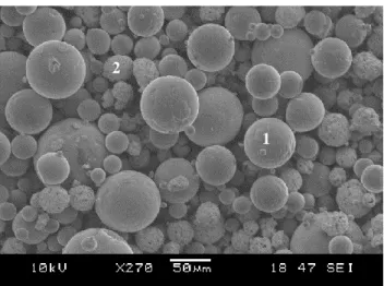
manufactured by Oerlikon Metco Company, its brand is Woka 3203. The size of the powder particles is principally in the range of 20 to 125 μm for the NiCrBSiFeC alloy and 20 to 53 μm for the WC(Co) powder. As the SEM micrograph (Fig. 1) shows, the particles for both powders are essentially spherically in shape.
Fig. 1. SEM morphology of a mixture of the as-received powders M30C: M (1), C (2)
A metal matrix composite material was elaborated by mixing 70 % of the metallic matrix NiCrBSiFeC with 30 % of the reinforcement cermet WC17Co, the resulting composite material is symbolized as M30C in this study. The chemical composition for both powders according to the manufacturer's data sheets is presented in Table 1.
Table 1. Chemical compositions of used powders Element, wt.%
Ni Cr B Si Fe C Co W M Bal. 15.2 3.2 4 4 < 0.6
C < 0.2 4.7–5.5 14.5–19.5 Bal.
Thermal spray coating was carried out on 40 × 40 × 10 mm AISI 1035 steel plates with an initial hardness and roughness (Ra) of 290 HV0.1 and 0.5 µm respectively. Sandblasting was used for the surface preparation of samples to clean and remove any trace of dirt, grease, rust and oxides that may be present on the surface. This is also done to create the necessary roughness to improve the coating adhesion to the substrate, Ra (4.3–5.6 µm).
The deposition of the coatings was achieved using flame thermal spray process (Fig. 2) according to the technological parameters given in Table 2. To guarantee adequate adhesion of the coatings to the substrate, a preheating of the substrate was carried out before spraying with the same spray torch (without powder). Prior to composite coatings deposition, a thin bonding interlayer of the metallic powder (NiCrBSiFeC) was applied using the same process. A non-contact infrared pyrometer was used to control the temperature of the substrate during preheating. The spraying was performed after reaching the desired temperature (200 °C–250 °C). The coatings were formed through sweeping the surface of a fixed substrate by the flame of the torch. A six-pass deposition was applied to obtain the required thickness (480 µm–550 µm).
2
Fig. 2. Flame thermal spraying process
The remelting of the sprayed coatings was immediately applied by flame post-heating with the same torch (without powder). The average remelting temperature was around 1050 °C.
Table 2. Flame spraying conditions
Parameter Value
Preheat temperature of the substrate, °C 200–250 Spraying distance, mm 60–90
Spraying angle 90°
Acetylene flow rate, l/h 400 Oxygen flow rate, l/h 440 Oxygen pressure, bar 2.5 Acetylene pressure, bar 0.6 Remelting distance, mm 15–20
Remelting angle 90°
2.2. Wear testing
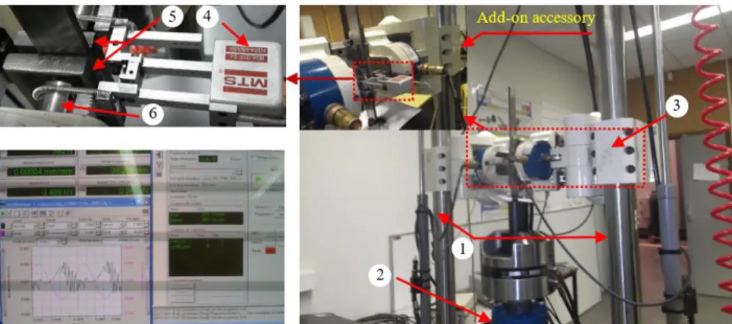
In this study, the friction and wear properties of the thermally sprayed coatings having undergone flame remelting were investigated under low-speed (10 mm/s) and high-load (500 N) in reciprocating dry wear conditions using a cylinder-on-flat test configuration. Fig. 3 shows a photo with details of the wear test equipment used in this present work. Wear experiments were conducted up to a total sliding distance of 200 m with a reciprocation amplitude of 10 mm at room temperature (about 25 °C). The pin used is an AISI 52100 steel cylinder with a 5 mm radius and a 10 mm length. All samples were polished and properly cleaned before tests
execution. The adapted equipment is a device that allows a conventional fatigue machine to be adapted as a tribometer to perform sliding of a reciprocating specimen under a stationary pin. This device adds a second axis to a usual fatigue machine in the form of an add-on accessory. The apparatus can also be used as a fretting-wear machine or a fretting-fatigue machine. This device is supported by a crosspiece (3: white), which is attached to the two columns (1) of a standard fatigue machine. Several pin shapes may be used with this device. The pins are fixed in the supports (6) and allow the specimen (5) to be pressed with a perfect symmetry in the form of a pinching motion. In the tribological configuration of the device, the specimen (5) is driven by the fatigue machine actuator in a vertical alternative movement. The friction force is measured using two load cells incorporated in the fatigue machine (2). The coefficient of friction (COF) is recorded in situ by means of acquisition software (Fig. 3) and the average COF is evaluated in the steady state zone. The wear depth corresponds to half of the measurement given by the extensometer (4). Details of the apparatus are reported elsewhere [11].
2.3. Characterization techniques
The achieved coatings are characterized in terms of microstructure, phase composition, hardness, wear resistance and friction. The microstructure investigation of the coatings was carried out on cross-sectioned and polished samples using a scanning electron microscope (SEM: Nova NanoSEM 450, FEI), equipped with an energy-dispersed X-ray analysis system (EDS-Genesis Apex 2i, EDAX). Phase identification study was accomplished by X-ray diffraction (XRD) analysis using a diffractometer with a CuKα radiation source (PanalyticalX’pert, Phillips). The mechanical properties of coatings were determined by indentations testing, specifically, Rockwell surface hardness and Vickers micro-hardness. The surface hardness was measured on the top surfaces of coatings with a 15 kgf load (HR15N). Micro-hardness measurements were carried out on cross-section of coatings using Vickers micro-hardness tester (MICROMET®, Buehler®) with a 100 g load (HV0.1) and a 10 s dwell time. For surface coatings roughness and wear assessment, profilometric and 3D topographic measurements were achieved using an extended field confocal microscope (Altisurf© 520, Altimet) and a dedicated software (AltiMap).
3. RESULTS AND DISCUSSION
3.1. Coatings microstructure
From the micrographs presented in Fig. 4 and Fig. 9, the layers of the as-sprayed coatings show a general lamellar structure with a few pores, oxides, and unmelted particles.
a
b
Fig. 4. SEM Comparative microstructure of as-sprayed coatings: a–NiCrBSiFeC; b–NiCrBSiFeC-WC(Co), the arrows indicate: 1–substrate-coating interface; 2–oxides; 3–pore; 4–unmolten particle;5–splat boundary.
Individual splats are well recognized, and small sized scattered precipitates can be clearly seen in almost all splats of the NiCrBSiFeC and the composite coatings. This has also been discerned in previous works [3–5, 13, 16]. The coating-substrate interface and splats boundaries are very clear and the substrate roughness profile stemming from surface preparation was preserved. This gives evidence that the coating bonding to the substrate and between splats are both essentially mechanical. In addition, single metallic (grey region) and cermet (white region) splats can clearly be observed in the composite coating. Moreover, the latter present less porosity and more flattened splats than the NiCrBSiFeC coating. The low porosity is thought be due to the small size WC(Co) particles that can be easily inserted into voids between the metallic particles thereby increasing the density.
As illustrated in Fig. 5–Fig. 7 and Table 3, the splats boundaries are completely eliminated and the surface roughness has intensely decreased for the two coatings NiCrBSiFeC and NiCrBSiFeC-WC(Co) after remelting compared to the as-sprayed coatings.
The two coatings exhibit practically almost pore-free, nanoscale grained and homogenized microstructure characterized by coarser well-dispersed precipitates, as well as small isolated rounded pores. This is in agreement with previous studies [9, 12–16]. In addition, the composite coating show molten (white) and unmolten (light grey) WC carbide particles well dispersed in the matrix.
a
b
Fig. 5. SEM Comparative microstructure of the remelted coatings: a–NiCrBSiFeC; b–NiCrBSiFeC-WC(Co). The arrows indicate:1–blocky precipitates; 2–rounded pore; 3–matrix; 4–unmolten WC carbides; 5 molten WC carbides
It can obviously be noticed from Fig. 6 a that the boundary between the coatings and the substrate has totally disappeared, evidence of good adhesion.
a
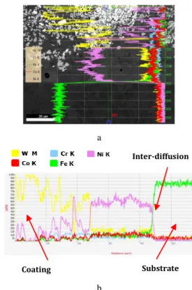
b
Fig. 6. SEM-EDS line scan profiles at the substrate-coating interface (green line) of the remelted NiCrBSiFeC-WC(Co) coating 4 3 2 5 1 4 3 1 2 3 4 5 2 Substrate Inter-diffusion zone Coating
a
b
Fig. 7. SEM/Element overlay cartography of remelted coatings. Left: NiCrBSiFeC; Right: NiCrBSiFeC-WC(Co)
SEM scan line analysis (Fig. 6 b) revealed the existence of a transition layer between the substrate and the remelted coatings. This is seemingly due to inter-diffusion phenomena occurring between the coating at its liquid state after remelting at high temperature and the substrate. The transition layer mainly contains Ni and Fe elements and is about 2.4 µm thick, evidence that the metallurgical bond has been successfully established. This is in line with previous studies [5–8, 16–18].
The elemental distribution in the composite NiCrBSiFeC-WC(Co) coating displayed in Fig. 7 b clearly shows that the cobalt attached to its original WC(Co) particle in the as-sprayed coating is uniformly redistributed throughout the microstructure after remelting. It is thought that the cobalt was dissolved in the Ni-based liquid alloy during the melting process because of its low melting temperature that can be reached during the melting process unlike the WC tungsten carbides. Accordingly, the resulting composite coating can be identified as WC carbide in a matrix of Ni-based alloy and Co. In addition, well-distinguished zones can be observed in both coatings. Based on elements’ color distribution these obviously correspond to silicides, tungsten carbides and chromium compounds.
Microstructural investigation of the coatings reveals a significant number of potential phases. According to SEM micrography, elemental distribution analysis, EDS measurements, X-ray diffraction results (Fig. 8) and previously published works [3–5, 9, 12], the microstructure of the NiCrBSiFeC coating is composed of Ni solid solution, borides (Ni3B, CrB), chromium carbides (Cr7C3) and silicides (Ni17Si3) uniformly distributed in the matrix. The latter consists principally of Ni solid solution and Ni-Ni3B as well as Ni-Ni17Si3 in the form of eutectic which is practically in accordance with previous works [3, 5, 19]. In addition, the composite coating comprises almost the same
phases and matrix but with cobalt as NiCrBSiFeC coating as well as WC, W2C and Co [4, 8, 20].
Fig. 8. XRD spectra of remelted coatings. Top: M30C; Below: NiCrBSiFeC
Besides, it is noticed that the chromium boride detected in the composite coating is Cr2B [13]. The W2C is obviously the result of WC decarburization at high temperature [2, 5]. As portrayed in XRD pattern (Fig. 8), it can be noticed that the coatings clearly exhibit broad peaks with humps, which are more expanded in the composite. This is more likely associated with nanocrystalline matrix phases resulting from the high cooling rates related to thermal spray coating process [2, 13, 15].
3.2. Mechanical properties
According to the hardness test results presented in Table 3, it can be noticed that the NiCrBSiFeC coatings exhibit significantly higher hardness values compared to the substrate, which is attributed to the presence of ultra-hard borides and carbides (CrB, Ni3B and Cr7C3) well-dispersed in a fine microstructure [5, 13, 21]. In addition, it is clearly shown that the composite coating has greater hardness values than NiCrBSiFeC coating both in as-sprayed and remelted conditions, as a result of the additional effect of the hard tungsten carbides particles.
Table 3. Summary of the coatings characteristics Coatings Roughness Ra,
µm HR15N Hv0.1 As sprayed M 8.86 ± 0.54 63.83 ± 2.47 753 ± 115 Remelted M 1.26 ± 0.25 88.95 ± 0.55 740 ± 51 As sprayed M30C 11.81 ± 0.73 67.64 ± 6.92 980 ± 154 Remelted M30C 1.88 ± 0.39 91.57 ± 1.27 852 ± 114
Similar results have been reported in previous works [4, 21, 22]. Furthermore, the micro-hardness is greater in the
In te n sit y Diffraction angle 2ϴ°
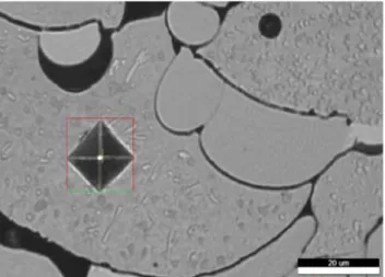
as-sprayed coatings while surface hardness is higher in remelted coatings, which is in agreement with reported results [5, 9, 23]. The high surface hardness of the remelted coatings could be mainly due to their high density owing to the reduction in porosity and enhancement of the coating cohesion as a result of the high temperature (1200–1500 °C) reached during the melting process [3, 9, 16]. The greater microhardness of the as- sprayed coatings may be due to their finer microstructure [5, 12, 15] (Fig. 9).
Fig. 9. Optical micrograph of an indent impression of as-sprayed NiCrBSiFeC coating under a load of 100 g
3.3. Wear behavior
The wear and friction properties of the substrate and the thermal sprayed coatings evaluated by the reciprocating cylinder-on-flat tests are presented in Table. 4.
Table 4. Tribological properties of the substrate and the remelted coatings
Max wear depth, µm Wear rate k×106, mm3/N·m Mean COF Substrate 144.35 ± 14.6 129.14 ± 28.7 0.7 ± 0.08 M coating 42.06 ± 0.7 21.11 ± 4.44 0.55 ± 0.04 M30C coating 18.89 ± 2.6 2.29 ± 0.87 0.60 ± 0.05
It can be established that both the NiCrBSiFeC and the composite coatings induced a significant increase in the wear resistance. A further improvement was promoted by adding the reinforcement phase WC(Co) in the composite coating. This is most likely the result of the hard borides, carbides and silicides formed during deposition and remelting processes as well as to WC carbides effect. Findings are consistent with previously reported results [3–6, 22, 24]. As discussed previously, this microstructure has produced a high hardness and better elastic properties [20], resulting in lower wear depth and reduced wear rate. Besides, the NiCrBSiFeC coatings provide the lowest mean COF, a slight increase was registered for the composite coating due to the hard phase (WC) effect which remain better than that recorded for the substrate [9, 14, 22].
Comparing to similar coatings deposited by other researchers, the results of the wear rate tests are very close to those of references [9, 12] and better than of that of reference [19]. Similar results for the COF are obtained in references [10, 23, 25, 28]. Furthermore, the wear rate
results for the remelted composite NiCrBSiFeC-WC(Co) coating were much better compared to recent published work on the same coating carried out by using plasma spraying [26]. This substantiates previous published results [3]. Therefore, the results obtained for the coatings wear resistance are good and confirm those reported in the previous works. Visual inspection of the wear tracks of the coatings revealed the presence of debris at the edges of the wear tracks and irregularly within, along and near the wear track. It has been noticed however, that part of the debris were continuously eliminated by gravity outside the wear tracks during the tests.
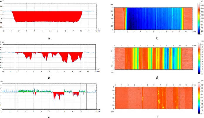
3D profilometry and SEM investigations of the wear tracks on the substrate and the coatings suggest that several wear mechanisms, promoted by the reciprocating dry sliding had occurred simultaneously. As shown in Fig. 10 b, two-body abrasive wear occurred in the substrate, characterized by deep grooves parallel to the direction of sliding resulting from the relative motion between a soft surface (substrate) against a counterpart with harder asperities (pin). Consequently, a large fluctuation in COF (0.7–0.95) was induced (Fig. 12 a). The small black spots that can be seen in the figure are thought to be due to low oxidation. For the NiCrBSiFeC coating (Fig. 10 d and Fig. 11 a and b), several macro and microgrooves parallel to the sliding direction related to the abrasion mechanism can be observed. In addition, a significant adhesion layer is obviously visible, which may have accumulated on both sliding surfaces by plastic deformation and flattening of the debris under continuous sliding [3,14,23]. The high mutual solubility of the Ni (coating) and the Fe (pin) contribute considerably to the development of this phenomena. Thereby, the adhesion layer is a result of material transfer from the counter-body which is mixed to coating debris and oxidized during the wear process to form a thin tribolayer [3, 23, 25]. This latter smoothed the worn surface and exerted a protective function to the coating, inducing a significant reduction in friction and wear (Table 4). As a result, a short running-in stage and a very stable COF were recorded for the NiCrBSiFeC coating (Fig. 12 b). Fig. 11 .b also shows some voids related to micro-porosities probably revealed by the wear process. Some of these contain indeed piled up debris inside. For the composite coating, wear particles agglomeration phenomenon is well observed. The smaller wear particles have linked together and formed a larger single pile. Particle agglomeration had occurred simultaneously in confined locations at the top and bottom edges of the wear area. Since the sliding is performed in the vertical direction, some fragments of debris piles were subsequently detached by gravity, trapped in the contact surface, and then partially embedded in the pin surface, thus acting as fixed indenters. As a result, large and shallow wear marks are clearly visible on the surface of the coatings (Fig. 10 f and Fig. 11 c and d) which is a sign of two-body abrasive wear mechanism [27]. The width of the mentioned wear marks are in the range of 258 µm to 1.58 mm, which may give an indication of the size of the debris piles. Some craters can be observed on the worn surface, mostly on the matrix and apparently bigger within the wear marks, which suggests that a part of debris (or agglomerated debris) remain free to roll between the two mating surfaces and may be the basis of a three-body abrasion wear mechanism [12, 27].
a b
c d
e f
Fig. 10. 3 D non-contact surface mapping with cross section of the wear scars (Right) and wear track profiles of remelted coatings (Left). a, b–substrate; c, d–NiCrBSiFeC; e, f– NiCrBSiFeC-WC(Co)
a b
c d
Fig. 11. SEM images of the worn surface of the remelted coatings: a, b–NiCrBSiFeC (1 debris; 2 grooves; 3 transferred layer; 4 micro-porosities); c, d–NiCrBSiFeC-WC(Co) (1 wear mark; 2 craters; 3 microfilm; 4 microgrooves; 5 micro-pits)
Some of these debris may be the results of the pulling out of the reinforcement phase. The craters are also visible in the counterpart supporting the idea of three-body wear mechanism. Due to this combined abrasive wear, the running-in stage was more extended and a large fluctuation in the COF is evident for the composite coatings (0.5–0.7)
(Fig. 12 c). The formation of a microfilm within the big marks and covering a large area of the wear track was also displayed (Fig. 10 f and Fig. 11 c). It is clearly indicated by the green area above the surface of the wear track (Fig. 10 e). This is a sign of tribo-oxidation mechanism, as reported in several previous research works [4, 10, 22, 28]. 1 mm 1 3 2 200 µm 2 3 4 3 2 1 2 1 mm 30 µm 4 5 2 3
a b c
Fig. 12. Coefficient of friction vs. sliding distance plots of the substrate and remelted coatings: a–substrate; b–NiCrSiBFeC; c–NiCrBSiFeC-WC(Co)
In contrast to the NiCrBSiFeC coating, no material transfer to the counter-body was detected. At high magnification (Fig. 11 d), it can be clearly seen that microgrooves are well noticeable on the matrix but interrupted in the WC carbides zone.
These may indeed have been generated by the hard carbides of WC previously extracted more likely by fatigue wear mechanism due to the alternative sliding [17], and which can become trapped between the sliding surfaces and cause the wear of the matrix. Micro-pits related to the pulled out carbides are obvious on the examined worn surface. Such phenomenon is not perceived in the NiCrBSiFeC coating.
4. CONCLUSIONS
In this study, the tribological behavior of thermally sprayed NiCrBSiFeC-WC(Co) composite and NiCrBSiFeC coatings were investigated in reciprocating dry sliding wear experiments based on a cylinder-on-flat test configuration. From this study, the main conclusions can be summarized as follows:
1. The tribological behavior of the substrate and the hard coatings were successfully studied thanks to the adapted machine, despite some difficulties encountered in the preliminary tests due to the high hardness of the composite coatings.
2. The high hardness and wear resistance of the coatings is attributed to the presence of well-dispersed ultra-hard borides and carbides in a refined microstructure as well as to WC carbides effect.
3. NiCrBSiFeC coatings may provide a further wear resistance more than ninefold that of the steel substrate. 4. The wear resistance of nickel based alloy coating was promoted by a factor of 6 as a result of the addition of the WC(Co) reinforcement phase for the composite coating forming.
5. Remelting can significantly improve the coating properties owing to enhancement of the density, the microstructure and the surface roughness (6–7 times). 6. The NiCrBSiFeC coating exhibited the lowest average
coefficient of friction (0.55), the latter being slightly affected by the addition of WC(Co).
7. The main wear mechanisms are abrasion wear in the substrate, tow-body abrasion wear and transferred layer in the NiCrBSiFeC coating. For the composite coating
abrasion wear, tribo-oxidation and fatigue wear are simultaneously present.
REFERENCES
1. Vuoristo, P. Comprehensive Materials Processing. Elsevier, 2014: pp. 229–276.
https://doi.org/10.1016/B978-0-08-096532-1.00407-6 2. Berger, L.M. Application of Hard Metals as Thermal Spray
Coatings International Journal of Refractory Metals and
Hard Materials 49 (3) 2015: pp. 350–364. https://doi.org/10.1016/j.ijrmhm.2014.09.029
3. Miguel, J.M., Guilemany, J.M., Vizcaino, S. Tribological Study of NiCrBSi Coating Obtained by Different Process
Tribology International 36 (3) 2003: pp. 181–187. https://doi.org/10.1016/S0301-679X(02)00144-5
4. Yao, S.H. Tribological Behaviour of NiCrBSi–WC(Co) Coatings Materials Research Innovations 18 (2) 2014: pp. 332–337.
https://doi.org/10.1179/1432891714Z.000000000436 5. Kim, H.J., Hwang, S.Y., Lee, C.H., Juvanon, P.
Assessment of Wear Performance of Flame Sprayed and Fused Ni-Based Coatings Surface and Coatings Technology 172 (2–3) 2003: pp. 262–269.
https://doi.org/10.1016/S0257-8972(03)00348-7
6. Gruzdys, E., Meškinis, S., Juraitis, A. Influence of WC/Co Concentration on Structure and Mechanical Properties of the Thermally Sprayed WC/Co-NiCrBSi Coatings Materials
Science (Medžiagotyra) 15 (1) 2009: pp. 35–39.
7. Gruzdys, E., Meškinis, S. Influence of Plasma Transferred Arc Process Parameters on Structure and Mechanical Properties of Wear Resistive NiCrBSi-WC/Co Coatings
Materials Science (Medžiagotyra) 17 (2) 2011: pp.140–144.
https://doi.org/10.5755/j01.ms.17.2.482
8. Yang, G., Huang, C., Song, W., Li, J., Lu, J., Ma, Y, Hao, Y. Microstructure Characteristics of Ni/WC Composite Cladding Coatings International Journal of Minerals,
Metallurgy and Materials 23 (2) 2016: pp. 184–192. https://doi.org/10.1007/s12613-016-1226-z
9. Houdková, Š., Smazalová, E., Vostřák, M., Schubert, J. Properties of NiCrBSi Coating, as Sprayed and Remelted by Different Technologies Surface & Coatings Technology 253 2014: pp. 14–26.
https://doi.org/10.1016/j.surfcoat.2014.05.009
10. Fernández, EM.R., García, A., Cuetos, J.M., González, R., Noriega, A., Cadenas, M. Effect of Actual WC Content on the Reciprocating Wear of a Laser Cladding
NiCrBSi Alloy Reinforced with WC Wear 324–325 2015: pp. 80–89.
https://doi.org/10.1016/j.wear.2014.12.021
11. Cheikh, M., Fermy, A. Prototype Fretting Device and Some Experimental Results Proceedings of the Institution of
Mechanical Engineers, Part J: Journal of Engineering Tribology 228 (3) 2014: pp.266–275.
https://doi.org/10.1177/1350650113503310
12. Navas, C., Colaço, R., de Damborenea, J., Vilar, R. Abrasive Wear Behaviour of Laser Clad and Flame Sprayed-Melted NiCrBSi Coatings Surface & Coatings Technology 200 (24) 2006: pp. 6854–6862.
https://doi.org/10.1016/j.surfcoat.2005.10.032
13. Sharma, P., Majumdar, J.D. Microstructural Characterization and Properties Evaluation of Ni-Based Hardfaced Coating on AISI 304 Stainless Steel by High Velocity Oxyfuel Coating Technique Metallurgical and
Materials Transactions A 44 (1) 2013: pp. 372–380. https://doi.org/10.1007/s11661-012-1407-y
14. Alidokht, S.A., Manimunda, P., Vo, P., Yue, S., Chromik, R.R. Cold Spray Deposition of a Ni-WC Composite Coating and its Dry Sliding Wear Behavior
Surface & Coatings Technology 308 2016: pp. 424–434. https://doi.org/10.1016/j.surfcoat.2016.09.089
15. Bergant, Z., Grum, J. Quality Improvement of Flame Sprayed, Heat Treated, and Remelted NiCrBSi Coatings
Journal of Thermal Spray Technology 18 (3)
2009: pp. 380–391.
https://doi.org/10.1007/s11666-009-9304-7
16. Karimi, M.R., Salimijazi, H.R., Golozar, M.A. Effects of Remelting Processes on Porosity of NiCrBSi Flame Sprayed Coatings Surface Engineering 32 (3) 2016: pp. 238–243. https://doi.org/10.1179/1743294415Y.0000000107
17. Lu, S.P., Kwon, O.Y., Guo, Y. Wear Behavior of Brazed WC/NiCrBSi(Co) Composite Coatings Wear 254 (5–6) 2003: pp. 421–428.
https://doi.org/10.1016/S0043-1648(03)00132-7
18. Lua, S.P., Kwon, O.Y., Guo, Y. Microstructure and Bonding Strength of WC Reinforced Ni-base Alloy Brazed Composite Coating Surface and Coatings Technology 153 (1) 2002: pp. 40–48.
https://doi.org/10.1016/S0257-8972(01)01555-9
19. Gómez-del Río, T., Garrido, M.A., Fernandez, J.E., Cadenas, M., Rodríguez, J. Influence of the Deposition Techniques on the Mechanical Properties and Microstructure of NiCrBSi Coatings Journal of Materials Processing
Technology 204 (1–3) 2008: pp. 304–312. https://doi.org/10.1016/j.jmatprotec.2007.11.042
20. Serres, N., Hlawka, F., Costil, S., Langlade, C., Machi, F. Microstructures and Mechanical Properties of Metallic
NiCrBSi and Composite NiCrBSi–WC Layers Manufactured via Hybrid Plasma/Laser Process Applied Surface Science 254 (12) 2011: pp. 5132–5137.
https://doi.org/10.1016/j.apsusc.2010.11.062
21. Rachidi, R., Elkihel, B., Delaunois, F. Microstructure and Mechanical Characterization of NiCrBSi Alloy and NiCrBSi-WC Composite Coatings Produced by Flame Spraying
Materials Science & Engineering B 241 2019: pp. 13–21. https://doi.org/10.1016/j.mseb.2019.02.002
22. Kekes, D., Psyllaki, P., Vardavoulias, M. Wear Micro-Mechanisms of Composite WC-Co/Cr-NiCrFeBSiC Coatings. Part I: Dry Sliding Tribology in Industry 36 (4) 2014: pp. 361–374.
http://www.tribology.rs/journals/2014/2014-4.html
23. González, R, García, M.A., Peñuelas, I., Cadenas, M., Fernández, M., Battez, A.H., Felgueroso, D. Microstructural Study of NiCrBSi Coatings Obtained by Different processes Wear 263 (1–6) 2007: pp. 619–624. https://doi.org/10.1016/j.wear.2007.01.094
24. Prince, M., Justin, T.A., Gopalakrishnan, P. Improvement in Wear and Corrosion Resistance of AISI 1020 Steel by High Velocity Oxy-Fuel Spray Coating Containing Ni-Cr-B-Si-Fe-C High Temperature Materials and Processes 31 (2) 2012: pp. 149–155.
https://doi.org/10.1515/htmp-2012-0009
25. Tillmann, W., Hagen, L., Stangier, D., Laemmerhirt, I., Dirk Biermann, D., Petra Kersting, P., Krebs, E. Wear Behavior of Bio-inspired and Technologically Structured HVOF Sprayed NiCrBSiFe Coatings Surface & Coatings Technology 280 2015: pp.16 – 26.
https://doi.org/10.1016/j.surfcoat.2015.08.055
26. Guo, H., Li, B., Lu, C., Zhou, Q., Jia, J. Effect of WC-Co Content on the Microstructure and Properties of NiCrBSi Composite Coatings Fabricated by Supersonic Plasma Spraying Journal of Alloys and Compounds 789 (15) 2019: pp: 966–975.
https://doi.org/10.1016/j.jallcom.2019.02.290
27. Vencl, A., Mrdak, M., Hvizdos, P. Tribological Properties of WC-Co/NiCrBSi and Mo/NiCrBSi Plasma Spray Coatings under Boundary Lubrication Conditions Tribology in
Industry 39 (2) 2017: pp. 183–191. https://doi.org/10.24874/ti.2017.39.02.04
28. García, A., Fernández, M.R., Cuetos, J.M., González, R., Ortiz, A., Cadenas, M. Study of the Sliding Wear and Friction Behavior of WC + NiCrBSi Laser Cladding Coatings as a Function of Actual Concentration of WC Reinforcement Particles in Ball-on-Disk Test Tribology Letters 63 (3) 2016: 41.
https://doi.org/10.1007/s11249-016-0734-3
© Abderrahmane et al. 2021 Open Access This article is distributed under the terms of the Creative Commons Attribution 4.0 International License (http://creativecommons.org/licenses/by/4.0/), which permits unrestricted use, distribution, and reproduction in any medium, provided you give appropriate credit to the original author(s) and the source, provide a link to the Creative Commons license, and indicate if changes were made.