HAL Id: hal-00639672
https://hal.inria.fr/hal-00639672
Submitted on 9 Nov 2011
HAL is a multi-disciplinary open access
archive for the deposit and dissemination of
sci-entific research documents, whether they are
pub-lished or not. The documents may come from
teaching and research institutions in France or
abroad, or from public or private research centers.
L’archive ouverte pluridisciplinaire HAL, est
destinée au dépôt et à la diffusion de documents
scientifiques de niveau recherche, publiés ou non,
émanant des établissements d’enseignement et de
recherche français ou étrangers, des laboratoires
publics ou privés.
Visual detection and 3D model-based tracking for
landing on aircraft carrier
L. Coutard, F. Chaumette
To cite this version:
L. Coutard, F. Chaumette. Visual detection and 3D model-based tracking for landing on aircraft
carrier. IEEE Int. Conf. on Robotics and Automation, ICRA’11, 2011, Shanghai, China, China.
pp.1746-1751. �hal-00639672�
Visual detection and 3D model-based tracking for
landing on an aircraft carrier
Laurent Coutard and Franc¸ois Chaumette
Abstract—A challenging task of airborne operations remains the landing on the carrier deck, which limits the carrier oper-ational efficiency during rough sea. In this paper, a method of carrier visual detection and tracking is described. With the help of the aircraft sensors, the carrier is first detected in the image using a warped patch of a reference image. This provides an initialization to a real time 3D model-based tracker estimating the camera pose during the sequence. This method is demonstrated and evaluated using a simulator with high-fidelity visualization and on real video.
I. INTRODUCTION
A. Aircraft carrier and landing
Since its origin during WWI, the aircraft carrier (AC) re-mains a major tool of sovereignty allowing the force projection across the world. Nowadays, the French Navy operates one carrier: the Charles de Gaulle (R91) powered by a nuclear reactor. It embeds a group of 40 aircrafts and helicopters.
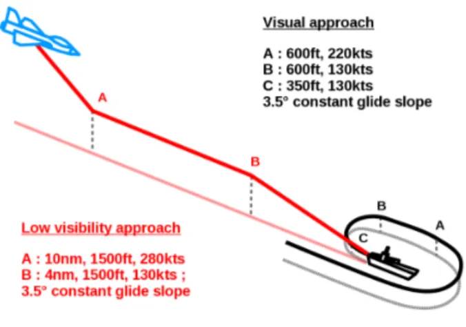
Landing on an AC is usually considered by pilots as a difficult task. Indeed, it consists in landing on a small deck in motion in almost all weather and visibility conditions. The approach trajectory mainly depends of the visibility as presented in Figure 1:
• In case of good visibility, the pilot begins a visual
approach, which consists in flying over the carrier and turning (point B of Figure 1) to align its aircraft to the runway deck axis (point C) while he begins its descent.
• In case of low-visibility or night approach, the procedure
begins at 18 km (10 nautical miles) of the AC (point A) and consists in the alignment to the deck axis with a constant glide slope of 4◦at 7.5 km (point B).
In french procedures, the pilot remains in the control loop with the help of aiding systems. The Optical Landing System provides the pilot a visual beam, which helps him follow an optimal trajectory until the touchdown. This system is actively controlled by the Landing Carrier Officer, located aboard the carrier. The pilot can land with the passive help of marks on the deck that allow him to control the aircraft glide slope and alignment.
B. Hypothesis and delimitation of the study
This study evaluates the possibility of using the vision sensor with other sensors on the aircraft to achieve later an autonomous landing by visual servoing. The study range is firstly defined between 10 nm (18 km) to 0.5 nm (900 m) to
The authors are with INRIA Rennes-Bretagne Atlantique and IRISA, Cam-pus de Beaulieu, 35042 Rennes cedex, France {Laurent.Coutard, Francois.Chaumette}@inria.fr
Figure 1. Visual and low-visibility approaches
the AC of the low-visibility procedure and secondly from 900 m to the touchdown.
Imaging sensors available on french aircraft fighters with characteristics compatible with the application are the Front Sector Optronics (FSO) and the Damocles multifunction-pod from Thales [1]. The FSO was discarded because its location prevents it from seeing the carrier during approach. The Damocles is located under the aircraft and has two fields-of-view of 1 and 4◦. Carrier and deck occupations in the image
are presented in Figure 2 with the two optics of the Damocles. This imaging sensor seems well suited for this application if the detection and tracking are effected in wide space.
Other sensors embedded on the aircraft can be used (e.g. Inertial Measurement Unit-IMU, radio-altimeter and TACAN). TACAN system is composed of an emitter on the AC and a receiver on the aircraft [2]. Receiver provides relative distance and azimuth between them to help the detection (see Figure 4a). Moreover, the carrier heading is known. Finally, the method does not rely on GPS in order to be autonomous.
Image tracking algorithm needs an initialization but TACAN distance and angular components are not accurate enough to provide a correct initialization. Hence, the carrier must be first detected in the image.
C. State of the art
In this application, detection localizes the carrier in the image. Then, the objective is to estimate the pose between the camera and the carrier using only the current image, and finally to track it along the sequence using the previous estimation.
Figure 2. Carrier and deck size in the image in function of the distance
1) Detection: In our application, detection consists in find-ing the carrier in the image and providfind-ing an initial pose to the tracking algorithm. The task is complex because variability of sea and weather conditions affects the appearance of AC which is designed to be the less visible as possible. In [3], low-level image processing techniques, as edge detection and multi-histogram matching, are used to segment the sky and the sea to finally extract the ship and its position in the image. This method is not invariant enough to visibility and does not provide an accurate localization in the image. Detection of the ship could be processed using motion segmentation as in [4]. A model of optic flow (OF) is computed using internal sensors and compared to the OF extracted from the image. Difference between these fields leads to obstacle localization. In this method, errors are mainly introduced by the OF extraction, which is often noisy. Moreover, in our application, waves constitute another source of noise.
2) Matching and pose estimation: Several papers present landing techniques on ship deck but mainly concern heli-copters, where the landing deck is defined by visible land-marks and the approach is vertical. In [5], some markers are segmented with histogram computation, and features used for localization are the corners of the shape, whose world coordinates are known using linear and nonlinear optimization. In the case of runways, detection can be performed using a model and some a priori data as approximate position. In [6], an exhaustive search is performed to find the best match and to determine the camera pose, which is quite expensive and does not ensure error minimization. Concerning the landing on carrier, the method presented in [7] consists in edge extraction and matching with a model. Segmentation and matching problems can be simplified using infrared emitting spots which are installed on the deck. In [8], only three points are used to compute the pose during a test flight. This method uses other sensors to improve and to filter the result and is subject to singularities and inaccuracy.
3) Tracking: Tracking methods use previous positions of (2D or 3D) features to estimate the new position. In [9], a corner snake method is used to segment a runway from a rough initial position and to track it in the image without estimating the pose. Dense information of the image is used to directly estimate the projective transformation between the current and a reference image representing runway and large part of the tarmac in [10] and [11]. The pose with respect to the airport is estimated using the decomposition of the homography and the knowledge of the distance between runway and camera. [11] uses Mutual Information criterion which allows a multimodal-ity tracking between airborne infrared images and a satellite reference image. These dense methods are robust to luminance variation but are computationally expensive with large images. Moreover, a runway is a very large and free surface whereas a carrier deck is small and may be occupied in part by aircrafts and superstructures.
In this paper, the relative pose between an aircraft equipped with a roll-tilt camera and an aircraft carrier is estimated during approach and landing trajectories using a robust 3D model-based tracker [12] that uses edges as visual features. Tracker initialization consists in detecting the carrier by localizing the maximum correlation coefficient of a patch representing the AC with a region of the current image and then estimating the pose. This detection method is robust to luminance changes (e.g. due to weather) and benefits from dense image information to deal with limited occlusions and patch modifications due to presence of aircrafts on the deck.
This paper is organized as follows: in Section II, involved frames are defined. In Section III a detection method is proposed using aircraft sensors to define an image region where the carrier is searched to provide an initial pose to the tracker presented in Section IV. In Section V, detection and tracking algorithms are evaluated on synthetic and real images.
II. DEFINITIONS
Figure 3 represents the different frames involved. Assuming that the Earth is flat (which is true regarding the Earth radius and the study range), the x-axis of the plane frame F0is NED
(North-East-Down) oriented.
• Aircraft Body and AC frames (respectively Fb and Fac)
are conventionally with the z-axis oriented down.
• The frame Fd corresponds to the origin of the deck,
translated and rotated about its z-axis from the carrier frame. It is expressed by the constant known matrix
acM d.
• The frame Ftcorresponds to the location of the TACAN
beacon.
• The pose cMb between the camera frame Fc and the
aircraft body frame Fb is supposed to be known along
the image sequence.
• Frame Fbo corresponds to the frame Fbwithout pitch and
Figure 3. Different frames of the problem
III. DETECTION
The detection consists in locating the aircraft in the first im-age to provide an initial pose to the tracker. Ideally, the tracker initialization could be computed with perfect aircraft sensors as IMU, radio-altimeter and TACAN beacon. Nevertheless, sensors inaccuracy involves uncertainties of AC position in the image which are not compatible with the tracker. That is why it is necessary to locate the AC and compute the initial pose. The detection is split in different parts:
• A search area of the image, where the deck origin
should be, is computed using available sensors and their accuracies.
• The carrier is located in the image by matching a
tem-plate with the current image using the maximum Zero-mean Normalized Cross Correlation (ZNCC) between the template and the image. The ZNCC detection is robust to luminance variation and to presence of aircrafts on the deck. To improve the results, the template is warped using the initial pose given by available sensors.
• Finally, the pose is computed with deck corners.
A. Search area in the image
The Damocles pod uses its degrees of freedom to focus the carrier in the image using TACAN information. If TACAN was perfect, deck origin would be the red dot of Figure 4b. Due to TACAN 2σ accuracies (respectively 185m, 1◦), the deck origin is within the red area of Figure 4b. This search area is used to reduce the search space of the carrier in the image. Sensors used are the aircraft IMU (providing ψb, θb, φb),
radio-altimeter (supposed to be ideal), TACAN beacon and carrier yaw ψac (others angles are neglected).
The origin of the deck, defined by its locationdX0in Fdis
projected in the image using the perspective projection model prξ(cMd,dX0) where cMd is the deck pose in the camera
frame and ξ are the camera intrinsic parameters. cM
d can be
decomposed in the following expression:
cM
d=cMb bMttMd (1) • tMd is the deck pose (known) in the TACAN frame.
• bMt =boM−1b boM
t whereboMb contains the rotation
part oRb(θb, φb) of aircraft pose and boM
t is the part
of the equation where TACAN distance and angular 2σ accuracies, δdt and δψr, are integrated:
boM t=
cos( ˜ψs) − sin( ˜ψs) 0 d˜tcos( ˜ψr)
sin( ˜ψs) cos( ˜ψs) 0 d˜tsin( ˜ψr)
0 0 1 oZ t−oZb 0 0 0 1 (2) with ˜ dt=p(dmt + δdt)2− (oZt−oZb)2 ˜ ψr= ψmr + δψr ˜ ψs= ψac− ψb+ δψr where dm
t and ψrm are the distance and angle between
the aircraft and the beacon provided by TACAN (see Figure 4a). These measures are statistically defined by normal laws: N(dt, σd2t) and N (ψr, σ
2
ψr) where dt and
ψrare true values with their respective variances σ 2 dt and σ2 ψr. Aircraft altitude oZ bis measured by radio-altimeter,
whereas the beacon altitudeoZ
t is a priori known.
The search area of Figure 4b is defined by its four corners computed by the maximum and minimum of the TACAN distance and angular 2σ accuracies, δdt and δψr. Moreover,
with the 1◦optics, search area exceeds the width of the image due to TACAN angular inaccuracy. In this case, detection is first applied with the 4◦optics and then improved with the 1◦optics.
(a) (b)
Figure 4. (a) TACAN measures ψrand dt. (b) Image taken at 2500 m with
respect to the carrier with a 4◦FOV; Deck origin (red dot) estimated with an
inaccurate TACAN; Search area (in red) due to TACAN 2σ inaccuracy
B. Warping
To improve the carrier detection in the image by maximizing the ZNCC, the reference image Ir is warped. Ir is taken at
a known pose crM
d with given camera parameters Kr. The
transformation cMc
r between the reference and the current
pose (using TACAN) is computed as:cMc
r =
cM
dcrM−1d .
The homographycH
cr is built using the plane P(
crn,crd)
defined by the deck where cR cr and
ct
cr are extracted from
cM cr. cH cr = cR cr + ct cr crd crn⊤ (3)
and the warping matrixcWc
r linking pixels of reference and
current image is given by:
cW cr= K cH cr K −1 r (4)
The image Iw used for ZNCC detection is equal to
Ir(cWcr) where the template of the deck It is extracted as
presented in Figure 5 using deck corners coordinates.
(a) (b) (c)
Figure 5. (a) Reference Ir, (b) warped image Iw, (c) patch It
C. Detection by correlation
This step of the method consists in localizing the carrier in the image by computing a similarity criterion between the patch Itpreviously defined and the window of the image over
all the search area defined in Section III-A. The ZNCC formula can be found in [13]. The maximum of the ZNCC corresponds to a possible location of the carrier. With the template It of
Figure 5c whose histogram covers a wide part of the grey value range [0;255] with the white parts of the deck, an efficient detection is obtained. Carrier is located in the image and deck corners position in the template image is known, and then in the current image. The initial pose of the tracker cM
d is
then computed with a classical pose estimation method using Virtual Visual Servoing (VVS) [14] from four points (deck corners).
IV. 3DROBUST MODEL-BASED TRACKING
The method used to track the AC in the image sequence is fully described in [12]. In summary, this algorithm consists in estimating the camera pose by minimizing the error between the observed data s∗ and the position s of the same features
determined by the projecting model according to the current pose. This method needs an initial pose cM0
o and a model
of the visible edges to project them in the image. Each projected segment is sampled. For each point, a search for the highest gradient is performed at the normal of the edge. Once this step is realized for all points, an error is defined and minimized by VVS which directly provides the estimated pose between the camera and the AC. This algorithm has already been applied to tracking elements in space applications with stereo camera [15] and in microassembly of Micro Electro Mechanical Systems [16].
V. RESULTS
The proposed method was tested both with a high-fidelity simulator and on real images. Each sequence represents a part of the two kind of approaches presented in Figure 1. Sequences and results are presented in the enclosed video.
A. Results on synthetic images
In order to evaluate method efficiency, we developed a simu-lator based on the XPlane game as a high-fidelity visualization and the Nimitz AC model. The software, developed with the ViSP library [17], is interfaced to XPlane via UDP socket using the Xplane Software Development Kit (SDK) [18]. The SDK provides access to many variables as camera, plane and aircraft pose, visibility, weather and sea state at 25Hz.
In this simulation, the aircraft is making a flying over the aircraft carrier at 200m above sea level. Trajectory and attitude are recorded from a real flight. This kind of trajectory is representative of the first part of the approach when the aircraft turns and realigns to the deck (see Figure 1). The carrier makes a straight line with a calm sea with no attitude movement. The ”roll-tilt” camera Damocles focuses the carrier in the image center during all the flying over. Moreover, the image is artificially degraded by addition of blur and noise.
In the following image sequence, tracking is initialized using the detection method described in Section III with the warped patch of Figure 6a. To demonstrate the method robustness, the patch was degraded by adding aircrafts on the deck and smoke from catapults. The tracking is performed from about 2950 to 400 meters of the carrier with the same 4◦optics, which corresponds to a AC size in the image of
30% to more than 100% according to Figure 2. Evolution of the carrier in the image is presented on Figures 6b to 6e. The external contour and the 3D superstructure of the carrier stabilize the estimation, especially when the carrier is small and the deck appears very oriented in the image. The estimated pose acM
b between the aircraft and the carrier is compared
to the real one in Figure 6f and 6g. As shown on Figure 6g, estimation results regarding the distance toward the AC are good, even during the first part of the sequence, when the deck is very oriented with respect to the camera (average errors of 6 meters and 0.2 degree on the x-axis and for φ angle) as presented on Figures 6b and 6c. Furthermore, in the second part of the sequence where the deck is more visible, the position and orientation average errors remain respectively under 0.72 meter and 0.02 degree.
Table I sums up the statistical results on each axis ofacM b.
The sensibility of the pose computation is closely dependent on the distance between the camera and the object. That is why error and standard-deviation of the distance are presented in percentage whereas angles are directly presented as error in degrees because these values are small. Pose estimation results are low regarding the distance with respect to AC and obtained without any filtering or fusion. The algorithm time computation mean is about 25 ms with a standard deviation of 8.5 ms over the sequence of 1024×768 images with a 3.06 GHz processor.
B. Results on real images
Since videos recorded from large distance with narrow FOV camera are not available, and good quality videos with embed-ded camera are rare, a video taken from a TV documentary on French Naval Aviation was used [19]. The camera is located
X (%) Y (%) Z (%) ψ (◦) θ (◦) φ (◦)
µ 0.25 0.17 0.08 0.01 0.01 -0.13 σ 0.38 0.46 0.70 0.03 0.04 0.43
Table I
MEAN AND STANDARD DEVIATION OF THE TRACKING ERROR FOR THE SIMULATION SEQUENCE
in the aircraft cockpit, involving distortions and reflections into the glass. Video is very blurry due to precision and resolution of the camera (unknown) and internet compression. The aircraft is in the final approach, near point B of the visual approach of Figure 1. Due to the wide camera FOV (40◦),
detection efficiency is proved on limited range, but can be extended to larger range using narrow FOV.
1) Detection: Template image warping cannot be used because no data are available for this video. In this case, detection consists only in finding an AC patch in the image as presented in Section III-C and robustness of the method relies on coefficient invariance with respect to luminance and warp. Figure 7f presents the maximum ZNCC along the sequence for the five patches of Figures 7a to e. We can see that this coefficient remains high over frames. For instance, 170-th patch coefficient is superior to 0.8 from 170-the 140-170-th to 170-the 205-th frame. That is why detection can be validated using a threshold on the ZNCC value for a given patch. Search of the maximum coefficient allows an efficient detection and tracking initialization. Using a database of these five different patches, detection is achieved from the 75-th to the 262-th frame (Figure 7f), corresponding to a distance wrt the AC from 700 to 250 meters. Even without any search area computation (it is the entire image) or warping, the detection by correlation allows a robust tracking initialization.
2) Tracking: The tracker is initialized at the 125-th frame using the 170-th frame patch (Figure 7d). Because the patch is not warped, pose estimation (Figure 8e) and model projection during the first frames (Figure 8a) are not perfect. But after 30 frames, the tracker succeeds to localize the carrier (Figure 8b) and to track it until its disappearing by the aircraft radome occlusion 175 frames later (Figure 8d). Tracking is robust to luminance variations due to the sun reflections and artifacts in the cockpit. The algorithm time computation average is 14 ms with a standard deviation of 7 ms.
VI. CONCLUSION AND FUTURE PERSPECTIVES
A method using a correlation detection and a robust 3D model-based tracker has been applied to the localization of an aircraft carrier. This problematic is defined by its wide range of working and some on-board sensors allow to sim-plify the initialization of the tracking. The method has been demonstrated on simulation with blurred images and with a low-quality video on a representative part of the study range. To improve the application range, fusion with others sensors as IMU or aircraft and carrier internal models will be used.
A future objective is to close the control loop and evaluate visual servoing for this application, where the aircraft is by
nature a non-holonomic under-actuated vehicle. VII. ACKNOWLEDGMENTS
This work is supported by DGA and Dassault Aviation under contribution to Laurent Coutard’s Ph.D. grant. The authors would like to thank Nicolas Depinoy, Denis Deshayes and Paul Wilczynski from DGA Flight Testing.
REFERENCES
[1] “DAMOCLES, 3rd Generation Multi-function Targeting pod,” THALES Optronique, 2008.
[2] “2001 Federal Radionavigation Systems,” Department of Defense and Department of Transportation, Tech. Rep., 2001. [Online]. Available: http://www.navcen.uscg.gov/pdf/frp/frp2001/FRS2001.pdf
[3] G. Santhalia, N. Sharma, S. Singh, M. Das, and J. MulChandani, “A Method to Extract Future Warships in Complex Sea-Sky Background which May Be Virtually Invisible,” 2009 Third Asia Int. Conf. on
Modelling & Simulation, 2009.
[4] S. Sull and B. Sridhar, “Model-based obstacle detection from image sequences,” 1995 Int. Conf. on Image Processing (Vol. 2), 1995. [5] C. Sharp, O. Shakernia, and S. Sastry, “A vision system for landing an
unmanned aerial vehicle,” IEEE International Conference on Robotics
and Automation, vol. 2, 2001.
[6] T. Soni and B. Sridhar, “Modelling issues in vision based aircraft navigation during landing,” IEEE Workshop Appl. Comput. Vision, 1994. [7] Y. Le Guilloux and R. Feuilloy, “Approche et appontage assist´es par traitement d’image embarqu´e sur a´eronef,” AGARD, Aircraft Ship
Operations, 1991.
[8] O. Yakimenko, I. Kaminer, W. Lentz, and P. Ghyzel, “Unmanned aircraft navigation for shipboard landing using infrared vision,” Aerospace and
Electronic Systems, IEEE Transactions on, vol. 38, no. 4, pp. 1181–1200, 2002.
[9] C. Barat and B. Lagadec, “A corner tracker snake approach to segment irregular object shape in video image,” IEEE Conference on Acoustics,
Speech, and Signal Processing. USA, 2008.
[10] T. Gonc¸alves, J. Azinheira, and P. Rives, “Vision-based autonomous ap-proach and landing for an aircraft using a direct visual tracking method,”
International Conference on Informatics in Control, Automation and Robotics, 2009.
[11] A. Dame and E. Marchand, “Accurate real-time tracking using mutual information,” IEEE Int. Symp. on Mixed and Augmented Reality,
IS-MAR’10, October 2010.
[12] A. Comport, E. Marchand, M. Pressigout, and F. Chaumette, “Real-time markerless tracking for augmented reality: the virtual visual servoing framework,” IEEE Trans. on Visualization and Computer Graphics, vol. 12, no. 4, pp. 615–628, July 2006.
[13] R. Gonzalez and R. Woods, Digital image processing. Prentice Hall, 2008.
[14] E. Marchand and F. Chaumette, “Virtual visual servoing: a framework for real-time augmented reality,” Computer Graphics Forum, vol. 21, no. 3, pp. 289–298, 2002.
[15] F. Dionnet and E. Marchand, “Robust stereo tracking for space robotic applications,” IEEE/RSJ Int. Conf. on Intelligent Robots and Systems,
IROS’07, pp. 3373–3378, October 2007.
[16] B. Tamadazte, T. Arnould, S. Demb´el´e, N. Lefort-Piat, and E. Marchand, “Real-time vision-based microassembly of 3d mems,” IEEE/ASME Int.
Conf. on Advanced Intelligent Mechatronics, AIM 2009, pp. 88–93, July 2009.
[17] E. Marchand, F. Spindler, and F. Chaumette, “Visp for visual servoing: a generic software platform with a wide class of robot control skills,”
IEEE Robotics and Automation Magazine, vol. 12, no. 4, pp. 40–52, December 2005.
[18] [Online]. Available: http://www.xsquawkbox.net/xpsdk/mediawiki/ Main Page
[19] [Online]. Available: http://www.dailymotion.com/video/xbpj9u ep04-a-l-ecole-des-pilotes-de-c%has tech
(a)
(b) 1st fr.: 2970m wrt AC (c) 143-th fr: 2125m wrt AC
(d) 286-th fr: 1270m wrt AC (e) 430-th fr: 430m wrt AC
(f)
(g)
Figure 6. 3D tracking after initialization with degraded patch (a); model projection according to the pose estimation (b to e); real and estimated poses between the carrier and the aircraft (f); pose error (g)
(a) 85-th (b) 100-th (c) 130-th (d) 170-th (e) 230-th
(f)
Figure 7. Maximum ZNCC evolution (f) along frame for different patches (a to e); Intervals of successful initialization
(a) 126-th fr. (b) 192-th fr.
(c) 260-th fr. (d) 330-th fr.
(e)