Open Archive TOULOUSE Archive Ouverte (OATAO)
OATAO is an open access repository that collects the work of Toulouse researchers and
makes it freely available over the web where possible.
This is an author-deposited version published in :
http://oatao.univ-toulouse.fr/
Eprints ID : 16650
To link to this article : DOI:10.1016/j.jpowsour.2016.08.017
URL :
http://dx.doi.org/10.1016/j.jpowsour.2016.08.017
To cite this version :
Brousse, Kevin and Huang, Peihua and Pinaud,
Sébastien and Respaud, Marc and Daffos, Barbara and Chaudret,
Bruno and Lethien, Christophe and Taberna, Pierre-Louis and
Simon, Patrice Electrochemical behavior of high performance
on-chip porous carbon films for micro-supercapacitors applications in
organic electrolytes. (2016) Journal of Power Sources, vol. 328. pp.
520-526. ISSN 0378-7753
Any correspondence concerning this service should be sent to the repository
administrator:
[email protected]
Electrochemical behavior of high performance on-chip porous carbon
films for micro-supercapacitors applications in organic electrolytes
K. Brousse
a,b, P. Huang
a,b, S. Pinaud
c, M. Respaud
c,d, B. Daffos
a,b, B. Chaudret
c,
C. Lethien
b,e, P.L. Taberna
a,b, P. Simon
a,b,*aCentre Inter-universitaire de Recherche et d’Ing!enierie des Mat!eriaux (CIRIMAT), UMR CNRS 5085, UPS, 118 Route de Narbonne, 31062 Toulouse Cedex 09,
France
bR!eseau sur le Stockage Electrochimique de l'Energie, FR CNRS n!3459, France
cLaboratoire de Physique et Chimie des Nano-Objets (LPCNO), UMR 5215 Institu National des Sciences Appliqu!ees (INSA)-Universit!e Paul Sabatier
(UPS)-CNRS, Universit!e de Toulouse, 135 Avenue de Rangueil, 31077 Toulouse, France
dAtelier Interuniversitaire de Micro-nano !Electronique (AIME), Universit!e de Toulouse, INSA, UPS, INP, 135 avenue de Rangueil, 31077 Toulouse Cedex 4,
France
eUniversit!e Lille 1 Sciences et Technologies, Laboratoire Institut d’Electronique de Micro!electronique et de Nanotechnologie (IEMN), UMR CNRS 8520,
Cit!e scientifique, Avenue Henri Poincar!e, CS 60069, 59652 Villeneuve d'Ascq Cedex, France
h i g h l i g h t s
" On-chip CDCfilms were prepared with different pore sizes and thicknesses. " Capacitance of 169 F cm#3was achieved in either ACN- or PC-based electrolytes.
" EMIþtransport limitation occurred for thicker films in more viscous 2M EMIBF 4/PC.
" High energy density was obtained for 7mm-thick CDC films in 2M EMIBF4/ACN.
Keywords:
Micro-supercapacitors Carbide derived carbon Electrochemical behavior Non-aqueous electrolytes
a b s t r a c t
Carbide derived carbons (CDCs) are promising materials for preparing integrated micro-supercapacitors, as on-chip CDCfilms are prepared via a process fully compatible with current silicon-based device technology. These films show good adherence on the substrate and high capacitance thanks to their unique nanoporous structure which can be fine-tuned by adjusting the synthesis parameters during chlorination of the metallic carbide precursor. The carbon porosity is mostly related to the synthesis temperature whereas the thickness of the films depends on the chlorination duration. Increasing the pore size allows the adsorption of large solvated ions from organic electrolytes and leads to higher energy densities. Here, we investigated the electrochemical behavior and performance of on-chip TiC-CDC in ionic liquid solvent mixtures of 1-ethyl-3-methylimidazolium tetrafluoroborate (EMIBF4) diluted
in either acetonitrile or propylene carbonate via cyclic voltammetry and electrochemical impedance spectroscopy. Thin CDC films exhibited typical capacitive signature and achieved 169 F cm#3in both
electrolytes; 65% of the capacitance was still delivered at 1 V s#1. While increasing the thickness of the films, EMIþtransport limitation was observed in more viscous PC-based electrolyte. Nevertheless, the
energy density reached 90mW h cm#2in 2M EMIBF
4/ACN, confirming the interest of these CDC films for
micro-supercapacitors applications.
1. Introduction
The myriad of portable electronic devices brings new needs in terms of mobility and autonomy, such as high performance mini-aturized energy storage systems. While batteries are used for en-ergy delivery, they still suffer from limited power capabilities and
* Corresponding author. Centre Inter-universitaire de Recherche et d’Ing!enierie des Mat!eriaux (CIRIMAT), UMR CNRS 5085, UPS, 118 Route de Narbonne, 31062 Toulouse Cedex 09, France.
E-mail address:[email protected](P. Simon).
cyclability, owing to the faradic nature of the electrochemical storage process.
Electrochemical double-layer capacitors (EDLCs), also called supercapacitors, store energy via reversible adsorption of ions from an electrolyte which is a fast non-faradic process, leading to high power densities and very long cycle life (more than 1,000,000 cy-cles) [1,2]. Therefore, this technology has already been used in broad range of applications in power electronics such as power buffer or memory back-up for toys, cameras, or mobile phones [1,3,4]. EDLCs are also used in transportation to recover braking energy in tramways, hybrid electric vehicles and buses[1,5].
Among various active materials, carbide derived carbons (CDCs) have spawned much interest as they offer a unique pore size and pore size distribution control by selectively etching metal atoms
from carbide powders, ceramics, felts and so on [6e13]. They
demonstrated great performances as their pore diameter was adapted to the ion size, leading to important capacitance gains [14,15]. These materials can even compete with pseudocapacitive
materials which deliver larger capacitance [16e19] but show a
decrease in power capabilities because of the faradic reactions ki-netics[18,20].
CDC powders have been widely studied in tetraalkylammonium tetrafluoroborate based electrolytes in acetonitrile (ACN)[8,21,22], propylene carbonate (PC) or
g
-butyrolactone[23], as well as inionic liquids such as 1-ethyl-3-methylimidazolium
tetra-fluoroborate [24e26] and 1-ethyl-3-methylimidazolium
bis(tri-fluoromethanesulfonyl)imide [27]. Unfortunately, mixing high
specific surface area carbon powders with a binder to prepare film electrodes does not fit with the requirements of the semi-conductor industry, where thickness control and good adherence on silicon chips are needed. To overcome this technological barrier, CDC began to be synthesized from the chlorination of metal carbide
films sputtered by physical vapor deposition technique [28],
allowing the direct integration of CDCfilms on silicon wafers to
prepare micro-supercapacitors [29,30]. These on-chip CDC films
showed very good adherence with rubber-like mechanical
prop-erties and delivered very high capacitance of 410 F cm#3 in 1M
H2SO4and 160 F cm#3in 2M EMIBF4in ACN[31]. However, so far,
no studies have addressed the influence of CDC films structure and texture on the electrochemical behavior in various electrolytes. This work investigates the electrochemical behavior and performance of
on-chip micrometer-thick TiC-CDC in EMIBF4 diluted in either
acetonitrile or propylene carbonate for micro-supercapacitors applications.
2. Experimental
2.1. Material preparation
TiC films were deposited by using a non-reactive direct current
magnetron sputtering technique (DC-MS) on Si/SiO2wafers. A TiC
target (99.5%, 10 cm diameter, 6 mm thick) was sputtered under argon atmosphere in the DP 650 sputtering equipment (Alliance Concept) under 0.01 mbar at 750!C as described in previous work
[31]. The power density was kept at 2 W cm#2during the sputtering
deposition. The thickness of the sputtered TiC thin films is controlled by the deposition time. Then the deposited TiC was placed in a furnace under argon purge. When the desired temper-ature was reached, the titanium carbide was converted to TiC-CDC by reacting with chlorine gas as described below (1):
TiC þ 2Cl2/ TiCl4þ C (1)
The chlorination time was carefully controlled to perform partial chlorination and obtain a CDC film strongly bonded to a residual
conductive TiC layer underneath[31].
Chlorination temperatures of 450!C and 700!C were selected to
prepare CDC films with different structure (pore size and pore size distribution). On-chip CDC films of more than 1 cm2were obtained (Fig. 1A). The structure of the TiC precursor is preserved after conversion into CDC for both 450!C (Fig. 1B and C) and 700!C
(Fig. 1D and E) chlorination temperatures, with continuous
columnar structure[31]. Cooling down was done under argon and
further annealing was performed at 600!C under H
2atmosphere to
remove residual chlorine species trapped into the nanopores[10].
2.2. Structural and electrochemical characterization
Raman spectra of the chlorinated CDC films were recorded using a Raman spectrometer LabRAM HR (Horiba Yvon-Joblin, 514 nm wavelength).
Gas sorption experiments were achieved on self-supported CDC films fully chlorinated at the desired temperatures and placed in a BELSORP-mini II (BEL, Japan) apparatus. The Ar and CO2adsorption
isotherms were used to estimate the Brunauer-Emmett-Teller (BET) surfaces and the pore size distributions.
The electrochemical characterizations of the Si/SiO2/TiC/CDC
were conducted using a Biologic VMP3 Potentiostat in 2M EMIBF4
either in acetonitrile or propylene carbonate (conductivities of 60 mS cm#1and 17 mS cm#1in ACN and PC, respectively)[32]in a
three-electrode configuration. All experiments were carried out at
room temperature under Ar atmosphere (O2 and H2O contents
lower than 0.1 ppm). A silver wire was used as quasi-reference and a Pt foil as counter electrode. Electrochemical impedance spec-troscopy (EIS) measurements were conducted on the freshly assembled cells by applying a 5.0 mVRMSsinusoidal signal
ampli-tude from 100 kHz to 10 mHz at the open circuit potential, and cyclic voltammetry was performed at several scan rates.
The electrolyte viscosities were measured with a MCR 301 Rheometer (ANTON PAAR, Austria) with a shear rate moving from 10 to 1000 s#1. Each measurement was repeated twice.
3. Results and discussion
3.1. Chlorination temperature influence
CDC film properties can be tuned starting from the same TiC thin film by changing the chlorination parameters such as tem-perature and time. The chlorination temtem-perature affects the structural and textural properties[6,14], modulating the pore size distribution, BET surface area, disorder and mechanical strength, while the chlorination time mostly controls the film thickness [31]. Fig. 2A shows the Raman spectra of 450 !C and 700 !C
partially chlorinated on-chip TiC-CDC samples. Whereas perfectly ordered graphite usually exhibits only one G-peak at 1580 cm#1,
corresponding to in-plane stretching, the second D-peak at
1350 cm#1 is associated with disordered carbons. Here, D-band
and G-band are clearly visible around 1340 cm#1and 1590 cm#1,
respectively, revealing the carbon is only partially graphitized for
both 450!C and 700!C chlorination temperatures. No peaks are
observed at low Raman shifts, confirming that titanium carbide
layer was successfully converted into CDC [33]. Furthermore, as
studied for SiC-CDC and Mo2C-CDC[34], the deconvolution of the
pics using a Gaussian-Lorentzian function evidences that the ID/IG
ratio changes while increasing the chlorination temperature, from 1.4 at 450!C to 1.7 at 700!C, with a noticeable shift of the G-peak
from 1585 cm#1to 1594 cm#1. This was also described for Ti3SiC2
ternary carbides[6]. As proposed by Ferrari and Robertson[35], the ID/IGratio is proportional to the square of the in-plane
appearance of both pics in visible Raman spectra depends fundamentally on the ordering of sp2sites and only weakly on the fraction of sp3sites[35]. Therefore the increase of the ID/IGratio
evidences to the progressive short-distance graphitization of the CDC film with increasing temperature, moving from an amor-phous structure to an ordered carbon.
The chlorination time was extended (20 min at 450 !C and
5 min at 700!C) to fully convert the metal carbide precursor into
CDC and separate the CDC film from the silicon substrate, as recently reported[31].Fig 2B shows the pore volume and the pore
size distribution of self-supported CDC films (using the CO2 gas
sorption technique) fully chlorinated at 450!C and 700!C. It gives
Gaussian-like narrow pore size distributions with a mean pore size increasing from 0.59 nm to 0.85 nm while increasing the chlori-nation temperature. This is consistent with previous studies on CDC powders[11]. Besides, the pore size distribution is extended and reaches 2 nm diameters at 700!C, while no pores larger than
1 nm are found in the CDC structure prepared at 450!C. As an
indication [36], the Brunauer-Emmett-Teller (BET) surfaces were
calculated to be 977 ± 30 m2 g#1 and 1026 ± 30 m2g#1for the
450 !C and 700 !C chlorinated self-supported CDC films,
respectively.
Electrochemical characterizations of the on-chip TiC-CDC films
partially chlorinated at 450!C and 700!C were achieved in 2M
EMIBF4 in ACN from cyclic voltammetry at various scan rates,
within a 3 V potential window. At 50 mV s#1(Fig 2C), the current response was normalized to the footprint area of CDC film. For the
450!C TiC-CDC sample, a typical rectangular shape is observed
between OCV (around þ0.4 V vs Ag) and þ1.3 V vs Ag, where the small BF4#adsorption occurs. However, a sieving effect[37e39]can
be seen between OCV and #1.7 V vs Ag, with a distortion of the CV appearing. This distortion is associated with the limited
accessi-bility of the larger EMIþ to the pores (mean pore size of about
0.6 nm), due to steric effects (bare cation size: 0.76 nm)[27].
The 700 !C chlorinated TiC-CDC exhibits a typical capacitive
signature within the entire voltage range of 3 V, as expected from the increase of mean pore size (1 nm). Same observation was done
on 800!C chlorinated TiC-CDC powders tested in cavity
micro-electrode in 2M EMITFSI in ACN[40]. Here the pores can
accom-modate both the anions and the larger cations.
Fig. 1. Preparation of CDC films onto Si wafer. (A) Optical view of on-chip CDC films chlorinated at 450!C (top) and 700!C (bottom). (B) SEM images of a 450!C chlorinated TiC-CDC surface and (C) cross-section of the layered Si/SiO2/TiC/CDC obtained after partial chlorination of 5 min performed on a 12.3mm-thick TiC film. (D) SEM images of a 700!C
chlorinated TiC-CDC surface and (E) cross-section of the 7.0mm-thick CDC film obtained after partial chlorination of 2.5 min performed on an 8.5mm-thick TiC film.
Fig. 2. Chlorination temperature influence. (A) Raman spectra of an on-chip CDC film chlorinated at 450!C and 700!C. (B) Pore size distribution of the nanoporous self-supported CDC films chlorinated at 450!C (open squares) and 700!C (solid circles) established from CO
2gas sorption. (C) CVs of a Si/SiO2/TiC/CDC electrode partially chlorinated at 450!C
(open squares) and 700!C (solid circles) after annealing 1 h under H
3.2. Influence of the solvent of the electrolyte
As expected from similar study on ionic liquid-solvent mixture of N-butyl-n-methylpyrrolidinium bis(trifluoromethanesulfonyl) imide (PYR14TFSI)[41], the electrolyte viscosity was found to be
higher in the IL-PC mixture than in the IL-ACN mixture, decreasing from 3.7 mPa s to 0.4 mPa s.Fig. 3shows the cyclicvoltammograms
of a Si/SiO2/TiC/CDC electrode chlorinated at 700 !C for 30 s
resulting in a 2.1
m
m-thick CDC layer, recorded at 50 mV s#1in both2M EMIBF4in ACN and 2M EMIBF4in PC electrolytes. The current
was normalized to the footprint area of electrode. Although both the electrolyte viscosity and resistivity are unfavorable when using PC as solvent (3.7 mPa s and 17 mS cm#1), all CVs exhibit a
rect-angular shape characteristic of a capacitive signature within the whole potential window (3 V) with similar capacitance. Indeed, the ions transfer kinetic into the porous carbon structure strongly de-pends on their diffusion coefficient, which is inversely proportional to the electrolyte viscosity. Then it can be estimated a characteristic
distance
d
along which the ions can accumulate on the materialsurface[42], given by(2):
d
¼ !D$R$T F$n
"0:5 (2)where D is the ions diffusion coefficient, R is the ideal gas constant,
T is the temperature, F is the Faraday constant and
n
stands for the scan rate applied during the cyclic voltammetry. A rough estima-tion of the in-pore effective diffusion coefficient of the ions in EMIBF4can be made assuming that its value is in the same order ofmagnitude than the one of similar BMIPF6ions, i.e. 10#6cm2s#1
[43]. As a consequence, this distance becomes 7
m
m at 50 mV s#1.Here, the small thickness of the CDC films (2.1
m
m) ensures fast and efficient ion transport into the porous carbon network. A slight current decrease at the OCV is responsible for the small deviation from the ideal rectangular shape. Such a minimum capacitance at the OCV has already been reported for AC, OLC and graphene [44e46]and is attributed to a change of electronic density of states under polarization, allowing electrons to occupy higher energy states[46]. Areal capacitance of 35 mF cm#2 (168 F cm#3) was delivered in both electrolytes, value in line with the volumetric capacitance reported in NEt4BF4/ACN[12].From electrochemical impedance spectroscopy data, the fre-quency dependence of the electrode capacitance was analyzed using the complex capacitance model[47]where the capacitance is written as follows(3):
Cð
u
Þ ¼ C0ðu
Þ # jC00
ð
u
Þ (3)The real C0(
u
) and imaginary C00
(
u
) parts of the capacitance aregiven by: C0ð
u
Þ ¼ #Z00ðu
Þu
# # #Zðu
Þ # # # 2 C00ðu
Þ ¼ Z0ðu
Þu
# # #Zðu
Þ # # # 2with
u
the angular frequency, Z0(u
) the real part and Z00(u
) theimaginary part of the impedance, and jZ(
u
)j the impedancemodulus. This model allows the qualitative study of the change of
Fig. 3. Influence of the solvent of the electrolyte. CVs at 50 mV s#1of a 2.1mm-thick
CDC electrode chlorinated at 700!C and tested in 2M EMIBF
4in ACN (open circles) and
PC (solid circles).
Fig. 4. (A) Change of the real and (B) imaginary parts of the capacitance vs frequency for a 2.1mm-thick CDC electrode chlorinated at 700!C and tested in 2M EMIBF
4in ACN (open
the capacitance with the frequency. Two parts are generally distinguished from C0vs frequency[47]. Capacitance change with
frequency is linked to the interaction of carbon porosity and the electrolyte. At high frequency regime, only the carbon surface is accessible for ion adsorption; as a result, the electrode capacitance is low and it behaves like a pure resistance (
f
z 0) [47]. Going down to low frequencies, the porous network becomes accessible to the ions so that the capacitance increases and reaches a plateau [47]. The change of the real part C0with frequency is presented onFig. 4A. The two cells present capacitive plateaus in low frequency range, evidencing that the maximum capacitance of the electrode is reached. C0sharply increases from 9 Hz to 200 mHz and tends to be
less frequency dependent in ACN- than in PC-based electrolyte. Although ions can access the entire carbon porous network in both electrolytes, the difference in the low frequency behavior originates from the difference in electrolyte permittivity and viscosity, as re-ported before[47].Fig. 4B plots the change of the imaginary part of
the capacitance C00 vs frequency. C00 corresponds to an energy
dissipation by an irreversible process that can lead to hysteresis, such as a dielectric loss in water[47]. The change of the imaginary
part C00with the frequency brings also additional information as it
goes through a maximum value at a frequency f0, related to a time
constant
t
0¼ 1/f0[47]. The supercapacitors power ability stronglydepends on this constant, giving the minimum time needed to achieve a discharge with an energy efficiency higher than 50%. Here the time constants are similar in both electrolytes, namely 0.9 s and 2.9 s in 2M EMIBF4in ACN and PC, respectively.
t
0is defined atf
¼ #45!and C0¼ C0LF=2 where CLF0 is the capacitance at low fre-quency. It can be seen onFig. 4A that half of the low frequency capacitance is reached at
t
0.The prepared on-chip micrometer-thick TiC-CDC film showed interesting performance in organic electrolytes, delivering a spe-cific energy of 44
m
W h cm#2(210 mW h cm#3) and a specific powerof 2.7 mW cm#2(12.6 W cm#3). These values challenge the CDC
film performance in 1.5 NEt4BF4/ACN[30].
3.3. Influence of the CDC film thickness
CDC film thickness can be tuned with the chlorination time. Increasing the electrode thickness increases the areal capacitance, and provides better energy delivery, as long as the electrolyte resistance in the porous network (the ion transfer limitation) is kept low. Starting from a sputtered TiC thin film (8.5
m
m-thick), on chip 7.0m
m-thick TiC-CDC were prepared by partial chlorination at700!C for 2 min 30 s. Samples were further annealed under H
2
atmosphere at 600!C for 1 h to remove trapped chlorine species
[10].
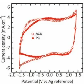
Fig. 5 shows the CV curves of the 7.0
m
m-thick CDC samplerecorded at 50 mV s#1in 2M EMIBF
4in PC and ACN electrolytes.
Capacitive signature is still observed in ACN based electrolyte within the whole potential window; the delivered capacitance is
72 mF cm#2 (103 F cm#3) which is twice that of the previous
capacitance obtained with thinner CDC layer. In the case of PC-based electrolyte, same rectangular shape can be seen between OCV (þ0.4 V vs Ag) and þ1.4 V vs Ag for anion adsorption. However, a distortion of the CV appears at negative potentials, leading to a
capacitance decrease down to 65 mF cm#2(92 F cm#3). Same
de-viation from ideal rectangular shape has already been reported for 700!C chlorinated TiC powders tested in 1.5 M NEt
4BF4in ACN[48].
The CV is not symmetrically distorted at positive potential values as it is expected for the ohmic drop in the bulk electrolyte, meaning that this distortion comes from a transport limitation of the EMIþ
Fig. 5. Influence of the CDC thickness. CVs at 50 mV s#1of a 7.0mm-thick CDC
elec-trode chlorinated at 700!C tested in 2M EMIBF
4in ACN (open circles) and PC (solid
circles).
cations in the porous network. In this thicker CDC layer, the
elec-trolyte viscosity affects the mobility of the larger EMIþ which
cannot occupy the entire porosity. Furthermore, chlorine species removal by annealing under hydrogen may be less homogeneous in thicker CDC layer, leading to a reduced ion mobility in the whole film. As a consequence, the material performance are reduced for 7.0
m
m-thick electrodes.The change of the capacitance real part C0vs frequency is plotted
inFig. 6A. Differently from the 2.1
m
m-thick CDC film, the capaci-tance of the 7.0m
m-thick film strongly depends on the frequency in both electrolytes. Because of the viscosity of the PC-based elec-trolyte, the capacitance is lower than that in ACN-based electrolyte in the whole frequency range. Aside, there is no evidence of the presence of a plateau at low frequency. Such features are explained, again, by the increase of the electrolyte resistance in the confined pores, in line with previous results [47]. The time constantst
0measured at the maximum C00 from Fig. 6B is ten times higher
(9.5 s) in 2M EMIBF4in ACN and twice higher (6.4 s) in 2M EMIBF4
in PC than for a 2.1
m
m-thick CDC film, reducing the CDC ability to fast charge and discharge.The preparation of a 7.0
m
m-thick CDC film at 700!C with amean pore size of 0.85 nm showed increased energy and power
performance (90
m
W h cm#2 and 5.3 mW cm#2) in ACN-basedelectrolyte. Moving from ACN to PC solvent comes with a
decrease in energy and power performance (81
m
W h cm#2and4.8 mW cm#2) because of increased electrolyte viscosity and
resistivity.
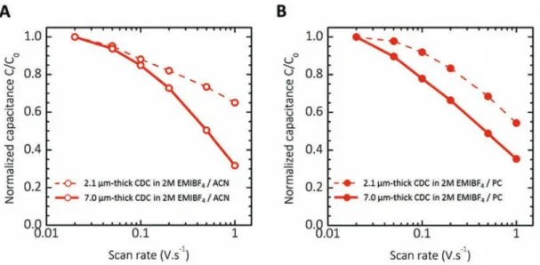
To further investigate the influence of the CDC thickness on the performance of the as-prepared electrodes, cyclic
voltam-metry tests were achieved at several scan rates from 20 mV s#1
to 1 V s#1 in both ACN- and PC-based electrolytes. The
capaci-tance was normalized to the maximum capacicapaci-tance C0, and
plotted vs scan rate (Fig. 7A and B). In 2M EMIBF4 in ACN, the
2.1
m
m-thick CDC film retains more than 65% of the capacitanceduring a 3 s discharge (1 V s#1), while only 32% of C
0are still
delivered for the 7.0
m
m-thick CDC film. These results are in line with the change of the capacitance vs frequency presented in this study. Indeed, the real part C0is still on the low frequency plateauat 0.33 Hz for the 2.1
m
m-thick CDC film, whereas it has alreadyreached the high frequency regime for thicker CDC layer. Same
observation was made in 2M EMIBF4 in PC, with 55% of the
capacitance delivered at 1 V s#1for the 2.1
m
m-thick electrode tobe compared with 35% for the 7.0
m
m-thick electrode. It is noted as well that while the scan rate increases, the capacitance value decreases faster in more viscous PC-based electrolyte, which is in agreement with the higher frequency dependence observed forthis sample (see Fig. 6). In addition, the capacitance value
delivered by the as-prepared on-chip CDC films was stable over 1000 cycles in both electrolytes (Supplementary materials, Fig. S1 and S2). These performance make these on-chip prepared electrodes appealing for designing high energy and power de-livery micro-supercapacitors.
4. Conclusion
Binder-free on-chip TiC-CDC films were produced by metallic atoms removal under chlorine atmosphere of sputtered TiC films on silicon wafer. Capacitive behavior within a 3 V potential range could be observed while tuning the pore size by increasing the
chlorination temperature from 450 !C to 700 !C. It allowed to
investigate the behavior of Si/SiO2/TiC/CDC electrodes in 2M
EMIBF4diluted in either ACN or PC. Regarding previous studies in
1.5 M NEt4BF4/ACN and 1 M NEt4BF4/PC [38,47], thin TiC-CDC
electrodes (2.1
m
m-thick) surprisingly showed no poreaccessi-bility restrictions of EMIþand BF 4
#while switching from ACN to
PC solvent, and delivered 169 F cm#3 at 50 mV s#1with good
power capability (65% of the capacitance was still delivered at a
scan rate of 1 V s#1). Expanding the CDC thickness up to 7
m
mbrought more frequency dependency in both electrolytes and a transport limitation of the larger cations was observed in PC-based electrolyte. In spite of the relation between larger thick-ness and ion accessibility, a huge specific energy of 90
m
W h cm#2was recorded in 2M EMIBF4in ACN, for a 5.3 mW cm#2 power
density, thus challenging the best on-chip electrode materials [31].
Acknowledgements
K.B. was supported by the Chair of Excellence from the Airbus Group. P.H. was supported by the French Government [Agence Nationale de la Recherche (ANR) ASTRID program, MISE project]. P.S. acknowledges funding from the European Research Council (ERC Advanced Grant 2011 n!291543, “Ionaces”project).
Fig. 7. Change of the capacitance with the scan rate for both 2.1mm-thick (dashed line) and 7.0mm-thick (solid line) CDC electrodes in (A) 2M EMIBF4in ACN (open circles) and (B)
Appendix A. Supplementary data
Supplementary data related to this article can be found athttp:// dx.doi.org/10.1016/j.jpowsour.2016.08.017
References
[1] P. Simon, Y. Gogotsi, Materials for electrochemical capacitors, Nat. Mater. 7 (2008) 845e854.
[2] T. Applications,http://www.maxwell.com/images/documents/datasheet_16v_ module.pdf, (accessed 30.05.16).
[3] J.R. Miller, A.F. Burke, Electrochemical capacitors: challenges and opportu-nities for real-world applications, Electrochem. Soc. 17 (2008) 53e57. [4] P. Simon, Y. Gogotsi, Charge storage mechanism in nanoporous carbons and
its consequence for electrical double layer capacitors, Philos. Trans. A Math. Phys. Eng. Sci. 368 (2010) 3457e3467.
[5] J. Miller, P. Simon, Electrochemical capacitors for energy management, Science 321 (2008) 651e652.
[6] Y. Gogotsi, A. Nikitin, H. Ye, W. Zhou, J.E. Fischer, B. Yi, H.C. Foley, M.W. Barsoum, Nanoporous carbide-derived carbon with tunable pore size, Nat. Mater. 2 (2003) 591e594.
[7] A. Erdemir, A. Kovalchenko, C. White, R. Zhu, A. Lee, M.J. McNallan, B. Carroll, Y. Gogotsi, Synthesis and tribology of carbide-derived carbon films, Int. J. Appl. Ceram. Technol. 3 (2006) 236e244.
[8] R. Dash, J. Chmiola, G. Yushin, Y. Gogotsi, G. Laudisio, J. Singer, J. Fischer, S. Kucheyev, Titanium carbide derived nanoporous carbon for energy-related applications, Carbon N. Y. 44 (2006) 2489e2497.
[9] S. Urbonaite, L. H€alldahl, G. Svensson, Raman spectroscopy studies of carbide derived carbons, Carbon N. Y. 46 (2008) 1942e1947.
[10] V. Presser, M. Heon, Y. Gogotsi, Carbide-derived carbons - from porous net-works to nanotubes and graphene, Adv. Funct. Mater. 21 (2011) 810e833. [11] C.R. P!erez, S.H. Yeon, J. S!egalini, V. Presser, P.L. Taberna, P. Simon, Y. Gogotsi,
Structure and electrochemical performance of carbide-derived carbon nano-powders, Adv. Funct. Mater. 23 (2013) 1081e1089.
[12] J. Chmiola, C. Largeot, P.L. Taberna, P. Simon, Y. Gogotsi, Monolithic carbide-derived carbon films for micro-supercapacitors, Science 328 (2010) 480e483. [13] V. Presser, L. Zhang, J.J. Niu, J. McDonough, C. Perez, H. Fong, Y. Gogotsi, Flexible nano-felts of carbide-derived carbon with ultra-high power handling capability, Adv. Energy Mater. 1 (2011) 423e430.
[14] J. Chmiola, G. Yushin, Y. Gogotsi, C. Portet, P. Simon, P.L. Taberna, Anomalous increase in carbon capacitance at pore sizes less than 1 nanometer, Science 313 (2006) 1760e1763.
[15] J. Chmiola, G. Yushin, R. Dash, Y. Gogotsi, Effect of pore size and surface area of carbide derived carbons on specific capacitance, J. Power Sources 158 (2006) 765e772.
[16] W. Sugimoto, K. Yokoshima, Y. Murakami, Y. Takasu, Charge storage mecha-nism of nanostructured anhydrous and hydrous ruthenium-based oxides, Electrochim. Acta 52 (2006) 1742e1748.
[17] T. Brousse, P.L. Taberna, O. Crosnier, R. Dugas, P. Guillemet, Y. Scudeller, Y. Zhou, F. Favier, D. B!elanger, P. Simon, Long-term cycling behavior of asymmetric activated carbon/MnO2aqueous electrochemical supercapacitor, J. Power Sources 173 (2007) 633e641.
[18] V. Augustyn, P. Simon, B. Dunn, Pseudocapacitive oxide materials for high-rate electrochemical energy storage, Energy Environ. Sci. 7 (2014) 1597. [19] F. B!eguin, V. Presser, A. Balducci, E. Frackowiak, Carbons and electrolytes for
advanced supercapacitors, Adv. Mater. 26 (2014) 2219e2251.
[20] A. Ferris, S. Garbarino, D. Guay, D. Pech, 3D RuO2microsupercapacitors with remarkable areal energy, Adv. Mater. 27 (2015) 6625e6629.
[21] B. Dyatkin, O. Gogotsi, B. Malinovskiy, Y. Zozulya, P. Simon, Y. Gogotsi, High capacitance of coarse-grained carbide derived carbon electrodes, J. Power Sources 306 (2016) 32e41.
[22] J. Leis, M. Arulepp, A. Kuura, M. L€att, E. Lust, Electrical double-layer charac-teristics of novel carbide-derived carbon materials, Carbon N. Y. 44 (2006) 2122e2129.
[23] A. J€anes, E. Lust, Electrochemical characteristics of nanoporous carbide-derived carbon materials in various nonaqueous electrolyte solutions, J. Electrochem. Soc. 153 (2006) A113eA116.
[24] H. Kurig, A. J€anes, E. Lust, Electrochemical characteristics of carbide-derived carbon/1-ethyl-3-methylimidazolium tetrafluoroborate supercapacitor cells, J. Electrochem. Soc. 157 (2010) A272eA279.
[25] J. Torop, V. Palmre, M. Arulepp, T. Sugino, K. Asaka, A. Aabloo, Flexible supercapacitor-like actuator with carbide-derived carbon electrodes, Carbon
N. Y. 49 (2011) 3113e3119.
[26] J. Segalini, E. Iwama, P.L. Taberna, Y. Gogotsi, P. Simon, Steric effects in adsorption of ions from mixed electrolytes into microporous carbon, Elec-trochem. Commun. 15 (2012) 63e65.
[27] C. Largeot, C. Portet, J. Chmiola, P.L. Taberna, Y. Gogotsi, P. Simon, Relation between the ion size and pore size for an electric double-layer capacitor, J. Am. Chem. Soc. 130 (2008) 2730e2731.
[28] E.N. Hoffman, G. Yushin, B.G. Wendler, M.W. Barsoum, Y. Gogotsi, Carbide-derived carbon membrane, Mater. Chem. Phys. 112 (2008) 587e591. [29] P. Huang, M. Heon, D. Pech, M. Brunet, P.L. Taberna, Y. Gogotsi, S. Lofland,
J.D. Hettinger, P. Simon, Micro-supercapacitors from carbide derived carbon (CDC) films on silicon chips, J. Power Sources 225 (2013) 240e244. [30] M. Heon, S. Lofland, J. Applegate, R. Nolte, E. Cortes, J.D. Hettinger,
P.L. Taberna, P. Simon, P. Huang, M. Brunet, Y. Gogotsi, Continuous carbide-derived carbon films with high volumetric capacitance, Energy Environ. Sci. 4 (2011) 135e138.
[31] P. Huang, C. Lethien, S. Pinaud, K. Brousse, R. Laloo, V. Turq, M. Respaud, A. Demorti#ere, B. Daffos, P.L. Taberna, B. Chaudret, Y. Gogotsi, P. Simon, On-chip and freestanding elastic carbon films for micro-supercapacitors, Science 351 (2016) 691e695.
[32] T. Nishida, Y. Tashiro, M. Yamamoto, Physical and electrochemical properties of 1-alkyl-3-methylimidazolium tetrafluoroborate for electrolyte, J. Fluor. Chem. 120 (2003) 135e141.
[33] B.H. Lohse, A. Calka, D. Wexler, Raman spectroscopy sheds new light on TiC formation during the controlled milling of titanium and carbon, J. Alloys Compd. 434e435 (2007) 405e409.
[34] H. Kurig, M. Russina, I. Tallo, M. Siebenbürger, T. Romann, E. Lust, The suit-ability of infinite slit-shaped pore model to describe the pores in highly porous carbon materials, Carbon N. Y. 100 (2016) 617e624.
[35] A. Ferrari, J. Robertson, Interpretation of Raman spectra of disordered and amorphous carbon, Phys. Rev. B 61 (2000) 14095e14107.
[36] M. Thommes, K. Kaneko, A.V. Neimark, J.P. Olivier, F. Rodriguez-Reinoso, J. Rouquerol, K.S.W. Sing, Physisorption of gases, with special reference to the evaluation of surface area and pore size distribution (IUPAC Technical Report), Pure Appl. Chem. 87 (2015) 1051e1069.
[37] L. Eliad, G. Salitra, A. Soffer, D. Aurbach, Ion sieving effects in the electrical double layer of porous carbon electrodes: estimating effective ion size in electrolytic solutions, J. Phys. Chem. B 105 (2001) 6880e6887.
[38] J. Segalini, B. Daffos, P.L. Taberna, Y. Gogotsi, P. Simon, Qualitative electro-chemical impedance spectroscopy study of ion transport into sub-nanometer carbon pores in electrochemical double layer capacitor electrodes, Electro-chim. Acta 55 (2010) 7489e7494.
[39] M.D. Levi, N. Levy, S. Sigalov, G. Salitra, D. Aurbach, J. Maier, Electrochemical quartz crystal microbalance (EQCM) studies of ions and solvents insertion into highly porous activated carbons, J. Am. Chem. Soc. 132 (2010) 13220e13222. [40] R. Lin, P. Huang, J. S!egalini, C. Largeot, P.L. Taberna, J. Chmiola, Y. Gogotsi, P. Simon, Solvent effect on the ion adsorption from ionic liquid electrolyte into sub-nanometer carbon pores, Electrochim. Acta 54 (2009) 7025e7032. [41] V. Ruiz, T. Huynh, S.R. Sivakkumar, A.G. Pandolfo, Ionic liquidesolvent
mix-tures as supercapacitor electrolytes for extreme temperature operation, RSC Adv. 2 (2012) 5591.
[42] E.J.F. Dickinson, R.G. Compton, Influence of the diffuse double layer on steady-state voltammetry, J. Electroanal. Chem. 661 (2011) 198e212.
[43] C. Pean, B. Daffos, B. Rotenberg, P. Levitz, M. Haefele, P.L. Taberna, P. Simon, M. Salanne, Confinement, desolvation, and electrosorption effects on the diffusion of ions in nanoporous carbon electrodes, J. Am. Chem. Soc. 137 (2015) 12627e12632.
[44] O. Barbieri, M. Hahn, A. Herzog, R. K€otz, Capacitance limits of high surface area activated carbons for double layer capacitors, Carbon N. Y. 43 (2005) 1303e1310.
[45] D. Weingarth, M. Zeiger, N. J€ackel, M. Aslan, G. Feng, V. Presser, Graphitization as a universal tool to tailor the potential-dependent capacitance of carbon supercapacitors, Adv. Energy Mater. 4 (2014) 1e13.
[46] C. Zhan, J. Neal, J. Wu, D.E. Jiang, Quantum effects on the capacitance of graphene-based electrodes, J. Phys. Chem. C 119 (2015) 22297e22303. [47] P.L. Taberna, P. Simon, J.F. Fauvarque, Electrochemical characteristics and
impedance spectroscopy studies of carbon-carbon supercapacitors, J. Electrochem. Soc. 150 (2003) A292.
[48] R. Lin, P.L. Taberna, J. Chmiola, D. Guay, Y. Gogotsi, P. Simon, Microelectrode study of pore size, ion size, and solvent effects on the charge/discharge behavior of microporous carbons for electrical double-layer capacitors, J. Electrochem. Soc. 156 (2009) A7eA12.