O
pen
A
rchive
T
OULOUSE
A
rchive
O
uverte (
OATAO
)
OATAO is an open access repository that collects the work of Toulouse researchers and makes it freely available over the web where possible.
This is an author-deposited version published in : http://oatao.univ-toulouse.fr/ Eprints ID : 18476
To link to this article : DOI:10.22364/mmp2017.9
URL : http://dx.doi.org/10.22364/mmp2017.9
To cite this version : Renaudière de Vaux, Sébastien and Zamansky, Rémi and Bergez, Wladimir and Tordjeman, Philippe and Bouyer, Viviane and Haquet, Jean-François Influence of Skin Depth on
Convective Heat Transfer in Induction Heating. (2017) In: VIII
International Scientific Colloquium Modelling for Materials Processing, 20 September 2017 - 22 September 2017 (Riga, Latvia)
Any correspondence concerning this service should be sent to the repository administrator: [email protected]
Influence of Skin Depth on Convective Heat Transfer in Induction
Heating
S. Renaudière de Vaux, R. Zamansky, W. Bergez, Ph. Tordjeman,
V. Bouyer, J.F. Haquet
Abstract
We investigate convection driven by induction heating of a horizontal fluid layer with direct numerical simulations (DNS). This problem is of particular interest in the context of nuclear severe accident mastering. In a real severe accident, the molten core is subjected to homogeneous internal sources resulting from nuclear disintegrations. This situation is mimicked in the laboratory using induction heating as the internal source. In induction heating however, heat sources are localized in the skin layer. Consequently, this concentration of heat may modify the flow and wall heat transfer, compared to the case of homogeneous internal sources.
DNS are carried out for three typical skin depths and three total deposited powers. Skin depth variations show surprising results regarding flow structures and heat transfer. It is found that the heat sources heterogeneity has a weak effect on flow structures. Consequently, models of heat transfer in the case of homogeneous sources remain valid even with strong localized heating near the bottom.
1. Introduction
Magnetic fields, whether AC or DC, are used in the industry for numerous purposes, such as electromagnetic stirring, induction heating or metal casting [1] [2]. Natural convection in the presence of DC magnetic fields has received a lot of attention, thanks to geophysical applications among others [3] [4]. The case of AC magnetic fields and induction heating is less studied, although it is of common use in the area of nuclear safety research in the context of severe accidents [5]. In the case of a nuclear core meltdown, the molten core (called corium) interacts with the concrete containment structures. This phenomenon is not yet fully understood. A key issue is the prediction of the convective wall heat transfer, since the ablation rate of the concrete is proportional to it [5]. Molten corium-concrete interaction (MCCI) is studied in the CEA Severe Accident laboratory to predict the ablation rate. To model the volumetric heat generation due to nuclear disintegrations, AC magnetic fields are used, as Joule dissipation mimics the volumetric power generation. In a real severe accident, the source term is more or less homogeneous. The relevance of MCCI tests relies on a low influence of the skin depth, which in this case is around 1 3⁄ of the pool size, on the wall heat transfer. The effects of source term concentration in the skin layer have to be analyzed. But heat transfer and fluid structures studies in experimental devices are complicated due to high temperature opacity, multiphase flow etc. As a model, we solve with DNS a horizontal fluid layer of thickness ℎ of an electrically conducting fluid, subjected to a horizontal AC magnetic field 𝐵0cos 𝜔𝑡 𝒆𝒙 as shown in Fig. 1, with 𝐵0 the imposed magnetic field amplitude at the bottom boundary and 𝜔 the pulsation. This case shares similarities with Rayleigh-Bénard
convection (RBC), although here, there is no imposed temperature difference. Diffusion of the magnetic field 𝑩 in the layer generates eddy currents 𝒋 = 𝑗(𝑧) 𝒆𝒚 over a characteristic length scale called the skin depth 𝛿 = √2𝜂/𝜔, with 𝜂 = 1/𝜇0𝜎 the magnetic diffusion coefficient, and a Joule heat source term 𝑗2/𝜎, with 𝜎 the fluid electrical conductivity and 𝜇0 the vacuum permeability. Moreover here, the Lorentz force is purely irrotational, 𝑭𝑳 = 𝒋 × 𝑩 = 𝐹𝐿(𝑧)𝒆𝒛, as the layer is infinitely horizontally wide. Therefore, the destabilization of the layer is only due to the temperature gradients, and this case is similar to convection driven by internal sources concentrated in the skin layer. When 𝛿 ℎ⁄ < 0.5, the Joule term is exponentially decaying from the bottom. The deposited power is given by the Rayleigh number 𝑅𝑎 = 𝑔𝛽ℎ3Δ𝑇/𝜈𝜅. Here, 𝑔 is the gravitational acceleration, 𝛽 is the fluid thermal expansion coefficient, 𝜈 is the fluid kinematic viscosity, 𝜅 the heat diffusivity and Δ𝑇 is a reference temperature proportional to the deposited power, defined in section 2. Similarly to RBC, the onset of the instability is characterized by a critical Rayleigh number 𝑅𝑎𝑐(𝛿 ℎ⁄ ). Linear stability analysis has been used to show that reducing 𝛿 ℎ⁄ promotes the destabilization of the layer, the critical Rayleigh number is slightly reduced [6]. Natural convection with homogeneous internal sources has been widely studied [7]. Recently, Goluskin & van der Poel [8] studied with DNS the case of uniform sources. Their results highlight non-symmetrical velocity profiles at sufficiently large 𝑅𝑎. In the case of AC magnetic field induced convection, concentration of heat in the skin layer is susceptible to fundamentally rework the flow. This could question the interpretation of MCCI tests. We investigate with DNS this problem for three characteristic skin depths, 𝛿 ℎ⁄ = 0.45, 0.14 and 0.04 and three total deposited powers. In section 2 we describe the studied problem and our numerical tools. In section 3 we analyze and comment our results regarding heat transfer and fluid structures.
2. Physical and numerical modelling
We consider small magnetic Reynolds number flows in an infinitely wide cavity in (𝑥, 𝑦) directions. The nondimensional electromagnetic field is governed by
𝜕𝑩 𝜕𝑡 = 𝑃𝑟 𝑃𝑚∆𝑩, 𝒋 = ℎ 𝛿∇ × 𝑩 (1) 𝑩 = cos 𝜔𝑡 𝒆𝒙, at 𝑧 = 0, (2) 𝑩 = 𝟎, at 𝑧 = 1. (3)
To nondimensionalize the length, time, magnetic field and current density, ℎ, 𝑡0 = ℎ2⁄𝜅, 𝐵0 and 𝑗0 = 𝐵0⁄𝜇0𝛿 are used, and 𝜔 a dimensionless pulsation. Here, 𝑃𝑟 = 𝜈 𝜅⁄ , 𝑃𝑚 = 𝜈 𝜂⁄ are the thermal and magnetic Prandtl numbers, 𝜔 is a non-dimensional pulsation. These equations are solved analytically, using a series expansion. Furthermore we assume that the magnetohydrostatic hypothesis is valid: the period of the magnetic field is much smaller than all other relevant hydrodynamic timescales [1]. This given, Lorentz force and Joule effect can be averaged over a period of magnetic field:
〈𝐹𝐿〉𝒆𝒛= 1 𝜏𝜔 ∫ 𝒋 × 𝑩 𝑡+𝜏𝜔 𝑡 d𝑡′ and 〈𝑗2〉 = 1 𝜏𝜔 ∫ 𝑗2 𝑡+𝜏𝜔 𝑡 d𝑡′, (4)
with 𝜏𝜔 = 2𝜋 𝜔⁄ . These terms are exponentially decaying in the 𝛿 ℎ ≪ 1⁄ limit as seen in Fig. . This given, the total space-time power deposited in the volume is Γ = ∫ 〈𝑗1 2〉 d𝑧
0 ≈
𝛿
2ℎ[1 − exp(− 2ℎ
𝛿)]. The Lorentz force in (4) can be rewritten as the gradient of a pressure term 〈𝐹𝐿〉𝒆𝒛= 𝛿 ℎ ∇〈𝑩⁄ 2〉/2. The studied configuration in Fig. 1 is governed by the non-dimensional Navier-Stokes equations, continuity equation, heat equation and boundary conditions are 𝜕𝒖 𝜕𝑡+ (𝒖 ⋅ 𝛁)𝒖 = −𝛁𝑝 ⋆+ 𝑃𝑟 ∆𝒖 + 𝑅𝑎 𝑃𝑟 𝑇𝒆 𝒛. (5) ∇ ⋅ 𝒖 = 0, (6) 𝜕𝑇 𝜕𝑡+ (𝒖 ⋅ 𝛁)𝑇 = ∆𝑇 + 1 Γ〈𝑗 2〉, (7) 𝒖 = 𝟎, 𝜕𝑇 𝜕𝑧 = 0 ⁄ at 𝑧 = 0, (8) 𝒖 = 𝟎, 𝑇 = 0 at 𝑧 = 1, (9)
with 𝑅𝑎 = 𝑔𝛽ℎ3Δ𝑇/𝜈𝜅 the Rayleigh number. Here 𝒖 = (𝑈, 𝑉, 𝑊), 𝑇 are the dimensionless velocity and temperature. The velocity scale is ℎ 𝑡⁄ 0. The modified pressure 𝑝⋆ is the pressure supplemented by the magnetic pressure, in units of 𝜌(𝜅 ℎ⁄ )2. The magnetic pressure is 𝐻𝑎2Pr2/𝑃𝑚 〈𝑩2〉/2 with 𝐻𝑎 = 𝐵
0ℎ √𝜎 𝜌𝜈⁄ the Hartmann number. As it has only a pressure component, the Lorentz force has no effect here. The boundary conditions (8) and (9) correspond to an insulating medium on the bottom and a perfect conductor on the top. The reference temperature used to nondimensionalize the equations is built as
Δ𝑇 =Γℎ 2 𝑗
02 𝜌𝑐𝑝𝜅𝜎
, (10)
similarly to [6]. This definition is based on the power deposited in the whole layer regardless of the localization (i.e. regardless of 𝛿 ℎ⁄ ). With this definition, 𝑅𝑎 is characteristic of the total deposited power.
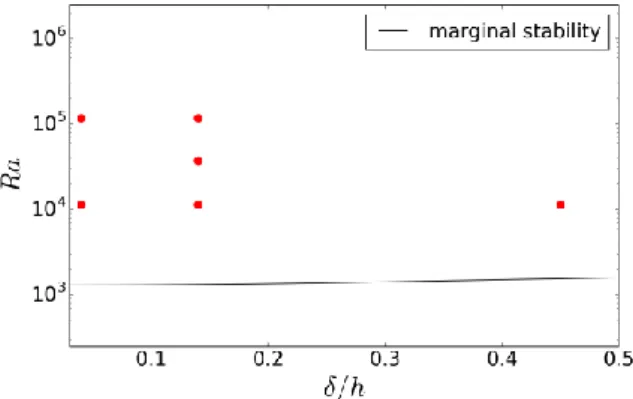
We solve (5) to (9) using the finite volume code Jadim [9] in a square box of horizontal aspect ratio 10 and periodic boundary conditions in horizontal directions. Lorentz force and Joule profiles from (4) and Fig. are prescribed in the DNS. To emphasize liquid metals, the values of the Prandtl numbers are fixed, 𝑃𝑟 = 0.025 and 𝑃𝑚 = 1.55 ⋅ 10−6. The computed points are given in Fig., with the marginal stability 𝑅𝑎𝑐(𝛿 ℎ⁄ ) (black line) on an indicative basis. With this set of points, it is possible to clarify the relative influence of 𝑅𝑎 and 𝛿 ℎ⁄ .
Fig. 2. Lorentz force (circles) and Joule term (solid lines) profiles for the computed points. The dashed lines represent exponentially decaying functions
Fig. 3. Computed points in the parameter space (red circles). The black line is the marginal stability 𝑅𝑎𝑐(𝛿 ℎ)⁄
3. Simulation results
3.1. Fluid structures
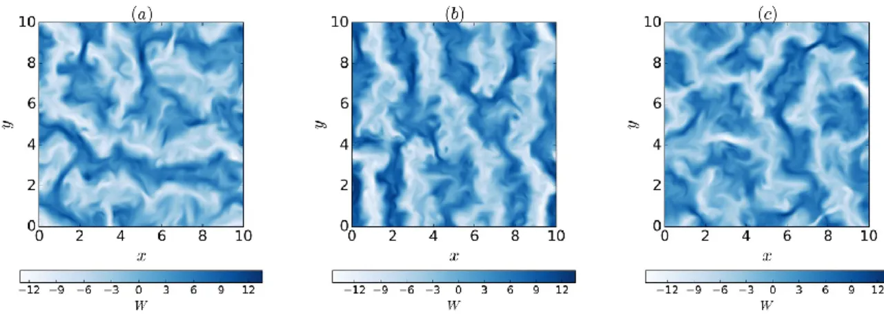
After a transient regime, the flow reaches a stationary regime, which we describe here. Instantaneous snapshots of the 𝑧-component of the velocity 𝑊 are shown in Fig. 4 for 𝑅𝑎 = 1.14 ⋅ 104. The flow structures are qualitatively identical, regardless of the skin depth.
Contrary to DC magnetic field convection, the flow exhibits a spectrum of wavelengths, and not a single observed wavelength [4]. The dominant wavenumber defined in Fig. 1 is around 𝑘 ≈ 2.5 for all cases, as it is the case in RBC [4]. Moreover, one notices that they share the same color scale. This means that for a same 𝑅𝑎, the characteristic kinetic energy 𝑊̅̅̅̅̅ is the same (the bar denotes averaging in the horizontal directions). It is balanced2 by the energy input, given by 𝑅𝑎. Therefore, one expects that
𝑊2
̅̅̅̅̅ ∼ 𝑅𝑎. (11)
This scaling is verified in DNS, where we find 𝑊̅̅̅̅̅ ∼ 𝑅𝑎2 0.95, which shows the poor influence of 𝛿 ℎ⁄ on the kinetic energy. Furthermore, the skin depth has a weak influence on the horizontal and vertical velocity profiles as seen in Fig. 5(a) and Fig. 5(b) respectively. The profiles are averaged in time and the bar denotes averaging in the horizontal directions. In Fig. 5(a), one sees that the boundary layer thickness (defined as the distance between the wall and maximum velocity) does not depend on 𝛿 ℎ⁄ : the curves at same 𝛿 ℎ⁄ are superimposed in the
Fig. 5. Vertical profiles of (a) horizontal velocity component and (b) vertical velocity component
Fig. 4. Snapshots of vertical component of velocity at 𝑅𝑎 = 1.14 ⋅ 104 and (a) 𝛿 ℎ = 0.45⁄ , (b) 𝛿 ℎ = 0.14⁄ , and (c) 𝛿 ℎ = 0.04⁄
boundary layer. However, as expected, it decreases as 𝑅𝑎 increases. The same conclusions are drawn for the vertical velocity profiles. The influence of 𝛿 ℎ⁄ on velocity profiles is weak. The maximum of √𝑊2 is located at 𝑧 = 1 2⁄ . The increase in preferential heating towards the bottom does not displace the maximum of √𝑊2. On the opposite, an increase in 𝑅𝑎 spreads the √𝑊2 profiles. The skin depth has a low influence on the convective structures. However, the preferential heating may modify the temperature profiles, and hence the heat transfer.
3.2. Heat transfer
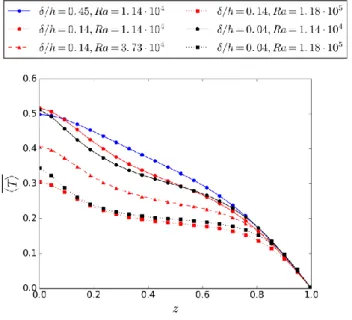
Fig. 6 gives the average temperature profiles. A loss of symmetry can be noted compared to the Rayleigh-Bénard case. This is due to the combined effect of the insulating condition (8) and of the non-symmetrical volume heating. The temperature difference between the top and the bottom is dictated by 𝑅𝑎. When 𝑅𝑎 increases, the bottom wall temperature decreases, due to convective motion, which eases the heat evacuation through the top. For 𝛿 ℎ < 0.45⁄ , all temperature profiles display an inflection point for 0.1 ≤ 𝑧 ≤ 0.3. For the case 𝛿 ℎ⁄ = 0.45, there is no inflection of 〈𝑇(𝑧)〉
̅̅̅̅̅̅̅̅. The inflection of temperature profiles is characteristic of RBC, except that in RBC, the profiles are symmetric. On the top, the deposited energy fixes the outward heat flux on the top in the stationary regime. With the reference temperature chosen in (10), the non-dimensional heat flux on the top is simply 𝜕𝑇 𝜕𝑧 = −1⁄ , as seen in Fig. 6. In the case of internal heating, the characterization of global heat transfer differs from the RBC case, since here the heat flux is fixed. In the case of homogeneous internal heat sources Goluskin & van der Poel [8] show that the non-dimensional mean fluid temperature is a good indicator of convective transfer and scales as
𝑇𝑚𝑒𝑎𝑛 ∼ 𝑅𝑎−1/5, (12)
for homogeneous sources, with 𝑇𝑚𝑒𝑎𝑛 = ∫ 〈𝑇(𝑧)〉̅̅̅̅̅̅̅̅𝑑𝑧 1
0 . They confirmed this law for homogeneous heating with DNS. In the case of concentrated heating in the skin layer, this scaling is still valid as seen in Fig.
7, which is a direct consequence of the low influence of 𝛿 ℎ⁄ on the temperature profiles (Fig. 6). For a constant 𝑅𝑎, the points at different 𝛿 ℎ⁄ are superimposed. The weak effect of the skin depth is due to sufficient mixing, which homogenizes the flow by
advecting heat. Fig. 7. 𝑇𝑚𝑒𝑎𝑛 vs. 𝑅𝑎. The dashed line is a linear fit of the data.
Conclusions
In this paper, we analysed with DNS the effects of the skin depth on convection generated by induction heating for 𝛿 ℎ⁄ < 0.5 and 104 < 𝑅𝑎 < 1.5 ⋅ 105. We showed that the features of classical RBC are observed in AC field generated convection. In this range of parameters, the skin depth has a weak influence and the heat repartition does not have influence on the flow. In particular, the skin depth influences very little the flow profiles (velocity and temperature) as well as integrated quantities (mean kinetic energy and mean temperature). This is due to sufficient mixing because the computed points are far from the marginal stability. At large magnetic Reynolds numbers, these conclusions are likely to change.
References
[1] R. Moreau, Magnetohydrodynamics, Springer, 1990.
[2] V. R. Gandhewar, V. Bansod and A. Borade, «Induction furnace - A review,» International Journal of
Engineering and Technology, vol. 3, n°14, pp. 277-284, 2011.
[3] J. Aurnou and P. Olson, «Experiments on Rayleigh–Bénard convection, magnetoconvection and rotating magnetoconvection in liquid gallium.,» Journal of fluid mechanics, vol. 430, pp. 283-307, 2001.
[4] S. Renaudière de Vaux, R. Zamansky, W. Bergez, P. Tordjeman and J. Haquet, «Magnetoconvection transient dynamics by numerical simulation,» The European Physical Journal E, vol. 40, n°11, p. 13, 2017.
[5] C. Journeau, P. Piluso, J. Haquet, E. Boccaccio, V. Saldo, J. Bonnet, S. Malaval, L. Carénini and L. Brissoneau, «Two-dimensional interaction of oxidic corium with concretes: The VULCANO VB test series,» Annals of Nuclear Energy, vol. 36, n°110, pp. 1597-1613, 2009.
[6] Y. Tasaka and Y. Takeda, «Effects of heat source distribution on natural convection induced by internal heating,» International journal of heat and mass transfer, vol. 48, n°16, pp. 1164-1174, 2005.
[7] D. Goluskin, Internally heated convection and Rayleigh-Bénard convection, Springer, 2015.
[8] D. Goluskin and E. van der Poel, «Penetrative internally heated convection in two and three dimensions,»
Journal of fluid mechanics, vol. 791, p. R6, 2016.
[9] J. Magnaudet, M. Rivero and J. Fabre, «Accelerated flows past a rigid sphere or a spherical bubble. Part 1. Steady straining flow,» Journal of fluid mechanics, vol. 284, pp. 97-135, 1995.
Authors
Sébastien Renaudière de Vaux Rémi Zamansky
Wladimir Bergez Philippe Tordjeman
Viviane Bouyer Jean-François Haquet
Institut de Mécanique des Fluides de Toulouse (IMFT) - Université de Toulouse, CNRS-INPT-UPS, Toulouse, France
E-mail: [email protected]
CEA, DEN, Cadarache, SMTA/LPMA, F13108 St Paul lez Durance, France