MINISTERE DE L'ENSEIGNEMENT SUPERIEUR ET DE LA RECHERCHE SCIENTIFIQUE
فيطس سابع تاحرف ةعماج
1
UNIVERSITE FERHAT ABBAS SETIF1 UFAS1 (ALGERIE)
THESE
Présentée à la Faculté de Technologie Pour l’Obtention du Diplôme de
Doctorat
Domaine : Science et Technologie Filière : Electronique
Option : Electronique et commande industrielle
Par
Mr. LAIB Abdelbaset
Commande robuste de systèmes photovoltaïques interconnectés au
réseau avec convertisseurs multi niveaux
Soutenue le : 02/05/2019 devant un jury composé de :
AMARDJIA Noureddine Professeur Univ. Sétif 1 Président
KRIM Fateh Professeur Univ. Sétif 1 Directeur de thèse
REKIOUA Toufik Professeur Univ. Bejaia Examinateur
LACHOURI Abderrazak Professeur Univ. Skikda Examinateur BADOUD Abdessalam MCA Univ. Sétif 1 Examinateur
A Robust Control for Grid-Connected PV
Systems using Multilevel Inverters
by
LAIB Abdelbaset
A thesis
presented to the University of Sétif 1
in fulfillment of the
thesis requirement for the degree of
Doctor of Philosophy
in
i
To my mother
To my Father
ii
Acknowledgement
In the name of ALLAH, the Most Gracious and the Most Merciful. Thanks to ALLAH who is the source of all the knowledge in this world, for the strengths and guidance in completing this thesis.
I express my deep sense of gratitude and heart-felt thanks to my supervisor, Prof. KRIM
Fateh, for his invaluable guidance, patience, kindness and consistent encouragement
throughout the course of this work. I am very glad that I have pursued my doctoral studies under his excellent supervision.
I would like to express my appreciation to my thesis committee members: Prof.
AMARDJIA Noureddine, Prof. REKIOUA Toufik, Prof. LACHOURI Abderrazak and Dr. BADOUD Abdesslem, for their discussions, suggestions, and feedbacks to improve my thesis.
I cannot forget to mention all my friends, LEPCI group, Dr. TALBI Billel, SAHLI
Abdeslem,KIHAL Abbes,Dr. FEROURA Hamza, Dr. BELAOUT Abdesslam, BOUYAHIA
Semcheddine, Dr.ARABI Abderrazak, MEDKOUR Hicham, BELGUIDOUM Fouzi, and BARA Seif, for their great friendship, help and support.
iii
Several grid-connected PV topologies are investigated in this dissertation for low, medium and high-power applications. Furthermore, an effective controller has been proposed for these topologies instead of conventional control strategies. The latter’s suffer from several drawbacks such as bad MPPT tracking, inaccurate grid power control, low grid current quality, hard implementation practically and variable switching frequency. To overcome these drawbacks, a model predictive control (MPC) strategy is proposed to control the power converters employed in the investigated grid-connected PV topologies. The major drawbacks of MPC strategy are variable inherent switching frequency and computational burden especially in case of high-level inverters. Therefore, these drawbacks are taking into account in the design of proposed controllers.
Firstly, an improved control strategy based on fixed switching predictive control strategy for three-phase dual-stage grid-connected PV system is proposed. A variable incremental current step size of an MPPT current oriented loop based on fixed-switching predictive current control is proposed and employed to control the DC-DC converter. While, a modified VOC based on predictive control strategy and space vector modulation (SVM) is employed to control the DC-AC converter.
Afterwards, High-level NPC inverters are employed in grid-connected PV system in order to inject a high produced PV power into the grid with high performance operation. On the other hand, a simple and effective model predictive control (MPC) algorithm is proposed for grid-connected PV system using high-level NPC inverter (six-level) that permits to inject the active power generated by the PV system, the reactive power demanded by the grid operator and assure the balance of DC-link capacitor voltages. Then, an optimized model predictive control (O-MPC) is proposed in order to achieve the same performance control provided by the MPC algorithm but with a significant reduction in computational burden.
Finally, a topology that divided the large PV array to string modules with individual DC-DC converter connected to a centralized multilevel inverter is investigated in order to overcome the problems resulted by connecting the PV modules as large PV array. Simple and effective controllers for this topology based on finite control set model predictive control (FCS-MPC) strategy is proposed. A voltage oriented maximum power point tracking (VO-MPPT) performed by an FCS-MPCC is applied for each DC-DC converter to draw the maximum power point from each string PV modules. In addition, an FCS-MPC controller is proposed to control the centralized multilevel NPC inverter connected to the grid.
The simulation and HIL results validate the proposed control schemes for the investigated grid-connected PV topologies.
Keywords: Photovoltaic energy, Grid-connected PV systems, Multilevel inverters, Maximum
iv
List of Figures………...………..viii
List of Tables………...…….xi
List of Acronyms……….………...………...xii
List of Symbols……….………..…………....xiii
Chapter1: Introduction
...……….1
1.1
I
NTRODUCTION………...……….…………...1
1.1.1STAND ALONE PV SYSTEMS ………...………
2
1.1.2GRID-CONNECTED PV SYSTEMS ……….
3
1.2
B
ACKGROUND OF GRID-
TIED PHOTOVOLTAIC SYSTEM TOPOLOGIES…....4
1.2.1SINGLE-STAGE GRID CONNECTED PV SYSTEM …………..………..4
1.2.2 DUAL-STAGE GRID CONNECTED PV SYSTEM ………..……….5
1.2.3 OTHER TOPOLOGIES ………..……….6
1.3
D
ISSERTATION MOTIVATION AND OBJECTIVES………....……….…...…7
1.3.1 INVESTIGATION OF SUSTAINABLE GRID-TIED PV SYSTEM TOPOLOGIES ...…..
7
1.3.2INVESTIGATION OF EFFECTIVE CONTROL SCHEMES ………..……
8
1.4
D
ISSERTATION ORGANIZATION...………...……..…….10
Chapter 2: Review of Control Techniques for Dual-Stage
Grid-Connected PV System
...……….12
2.1
I
NTRODUCTION...………..…..….……….………12
2.2
M
AXIMUM POWER POINT TRACKING………...………...……...12
2.2.1
PERTURB AND OBSERVE (P&O) ALGORITHM……….…13
v
2.2.5CURRENT-ORIENTED MPPT……….
17
2.2.6COMPARISON OF MPPT TECHNIQUES ………20
2.3
DC-L
INK CONTROL.………..………...…..…..20
2.3.1
DC-LINK CONTROLLERS BASED ON ARTIFICIAL INTELLIGENT…...……20
2.3.2
DC-LINK CONTROLLER WITH FEED FORWARD TERM…………...……21
2.3.3
OTHER DC-LINK VOLTAGE CONTROLLERS……….……21
2.4
O
VERVIEW OF GRID CURRENTC
ONTROLT
ECHNIQUES………
..…22
2.4.1 DIRECT POWER CONTROL BASED ON SWITCHING TABLE (DPC)….….…22 2.4.2STATIONARY FRAME VOC
……….……….…..23
2.4.3SYNCHRONOUS FRAME VOC
………24
2.4.4FINITE CONTROL SET MODEL PREDICTIVE CONTROL FOR VOLTAGE SOURCE CONVERTER TIED TO THE GRID ………...…………25
2.4.5COMPARISON OF FCS-MPC WITH CONVENTIONAL CONTROL SCHEMES.27
2.5
C
ONCLUSION………....
...………...29
Chapter 3: Improved Control of Three Phase Dual-Stage Grid
Connected PV System Based on a Predictive Control
Strategy
...………..30
3.1
I
NTRODUCTION………..…………..……….….30
3.2
P
ROPOSED CONTROL STRATEGY………...……….…………31
3.2.1 PROPOSED MPPT TECHNIQUE ……….…...….…
31
A. Variable Current Step Size Incremental Algorithm ………..…….
32
B. Fixed switching predictive current control ………..…………..
34
3.2.2PROPOSED PS-VOC CONTROL ………..
36
3.3
S
IMULATIONR
ESULTS………..38
3.3.1 VS-INC/PCC VERSUS INC/PCC AND CONVENTIONAL INC COMPARISONS………...…
40
vi
………
45
3.4
R
EAL-T
IMEHIL
I
MPLEMENTATION………...…...48
3.5
C
ONCLUSION………...….54
Chapter 4: Control of Grid-Tied PV System Using Multilevel
NPC Inverter Based on FCS-MPC
...………55
4.1
I
NTRODUCTION...………..………..………..…55
4.2
S
TATE OF THE ART OF GRID-
CONNECTEDPV
SYSTEM USINGM
ULTILEVEL INVERTER CONTROLLERS.………...…....…56
4.3
O
VERALL SYSTEM CONFIGURATION….……….………57
4.4
O
VERALL SYSTEMC
ONTROL………...……...……….……….58
4.4.1
MPPT TECHNIQUE AND DC-LINK REGULATOR …………………..58
4.4.2
GRID-CONNECTED MULTILEVEL INVERTER CONTROL STRATEGY...59
4.5
M
ODELING OF GRID-
CONNECTED SIX-
LEVELNPC
INVERTER……...59
4.6
D
ECOUPLED ACTIVE AND REACTIVE POWER STRATEGY FOR GRID-
CONNECTED SIX-
LEVELNPC
INVERTER………...………63
4.7
O-MPC
DECOUPLED ACTIVE AND REACTIVE POWER STRATEGY FOR GRID -CONNECTED SIX-
LEVELNPC
INVERTER………...………65
4.8
R
ESULTS ANALYSIS...………….………...…………..…….67
4.9
R
EAL TIME HIL IMPLEMENTATION RESULTS...……..………...….……..73
4.10
C
ONCLUSION...……….………..…....78
Chapter 5: Finite Control Set Model Predictive Control for
Large-Scale Grid-Connected Photovoltaic Systems using
High-Level NPC-Inverter
...………..79
vii
5.3
O
VERALL SYSTEM CONFIGURATION AND MODELLING………...………82
5.3.1DC/DCBOOST CONVERTER MODEL ……….…83
5.3.2GRID-TIED CENTRALIZED FIVE LEVEL NPC INVERTER MODEL ……….….…84
A. Modelling of grid currents in synchronous frame
…
………..85
B.
Modelling of DC-link capacitor voltages…
………..….…875.4
P
ROPOSED SYSTEM CONTROL……….……..….……88
5.4.1INDIVIDUAL MAXIMUM POWER POINT TRACKING
………..………88
A. IncCon voltage algorithm
………...…………89
B. PI compensator design
………90
C. FCS-MPCC for DC/DC boost converter
………...……….91
5.4.2FCS-MPC ALGORITHM FOR GRID-TIED FIVE-LEVEL INVERTER ..…….…...…..
92
5.5
R
ESULTS ANALYSIS………..…….96
5.5.1 PROPOSED CONTROL SCHEME VERSUS CONVENTIONAL CONTROL SCHEME COMPARISON
………..………...96
5.5.2PERFORMANCE OF PROPOSED CONTROL SCHEME UNDER CONTRAST OF POWER EXTRACTION FROM EACH PV SYSTEM
………....………102
5.6
C
ONCLUSION...……….……….………..….………....104
Chapter 6: Conclusions
...………...
.
105
6.1
G
ENERAL CONCLUSION……….…………...………..105
6.2
A
UTHOR’
S CONTRIBUTIONS...………..…….…...106
6.3
F
UTURE WORKS……….………....…109
List of Publications……….……….
110
References……….………...…….113
viii
Figure 1.1: Solar PV global capacity and annual additions, 2007-2017………….……….…..2
Figure 1.2: Global renewable power capacity, 2007-2017………..….….2
Figure 1.3: Single-stage grid-connected PV system topology ………...……...5
Figure 1.4: Dual-stage grid-connected PV system topology ………...……..5
Figure 1.5: Multi-string inverters topology ………...………6
Figure 1.6: Multi MPPTs with centralized inverter topology ………...…………7
Figure 2.1: Flowchart of the P&O algorithm ………..…...……...13
Figure 2.2: Flowchart of the INC algorithm ………...…….15
Figure 2.3: Diagram of Voltage-oriented MPPT method ………16
Figure 2.4: Flowchart of the V-P&O algorithm ………..……16
Figure 2.5: Flowchart of the V-INC algorithm ………..…...17
Figure 2.6: Diagram of Current-oriented MPPT method ………...….18
Figure 2.7: Flowchart of the C-P&O algorithm ………..……18
Figure 2.8: Flowchart of the C-INC algorithm ………...………...19
Figure 2.9: Diagram of DC-link voltage controller ………...…………..20
Figure 2.10: Diagram of DC-link voltage controller with feed forward term ……….21
Figure 2.11: Number of sectors with voltage vectors generated by VSI……….…………22
Figure 2.12: Direct power control (DPC) scheme ……….………..23
Figure 2.13: Stationary frame VOC scheme ………..…….24
Figure 2.14: Synchronous Frame VOC scheme ………...…...25
Figure 2.15: Finite control-set model predictive control (FCS-MPC) scheme ………..….26
Figure 2.16: Flowchart of finite control set model predictive control ( FCS-MPC)…..…..27
FIGURE 3.1:Proposed control strategy (A) proposed MPPT controller (B) DC-link voltage controller (C) proposed PS-VOC controller ………...…..31
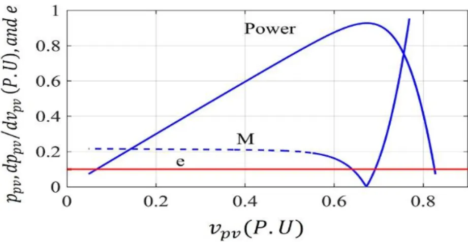
Figure 3.2: Basic idea of VS-INC current algorithm on P-V curve ………...….33
Figure 3.3: Flowchart of the VS-INC current MPPT ………..…....33
Figure 3.4: DC-DC equivalent circuit ……….……...…….34
Figure 3. 5: Flowchart of the Proposed PS-VOC ………..….….38
Figure 3.6: Performance of INC, INC/PCC and proposed MPPT under irradiation changes ………...41
ix
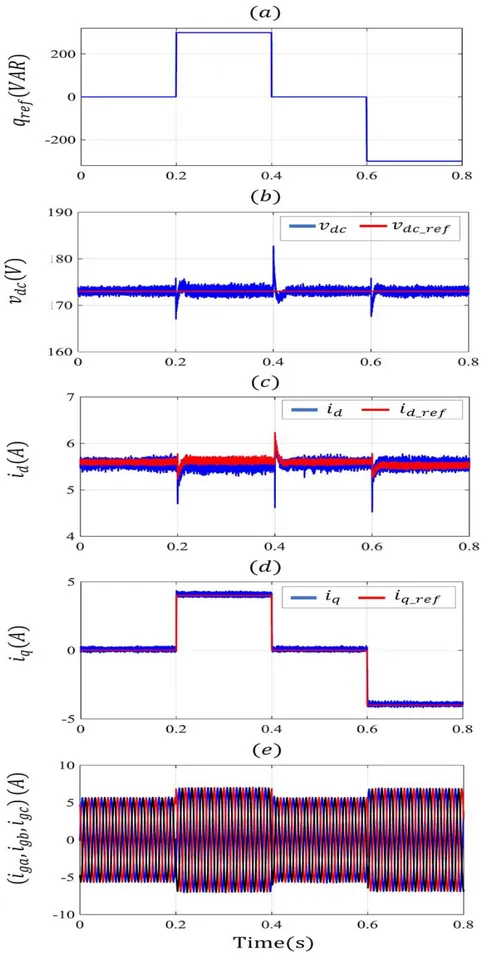
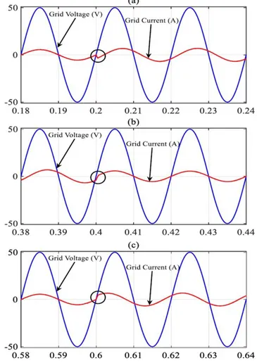
Figure 3.10: Performance of global system under reactive power grid operator demand
changes ………... 46
Figure 3.11: Grid current and voltage angle change under reactive power change ……….46 Figure 3.12: Diagram of hardware in the loop system (HIL)………...………48 Figure 3.13: Performance of conventional INC MPPT under irradiation changes …...…..49 Figure 3.14: Performance INC/PCC MPPT under irradiation changes ………...……50 Figure 3.15: Performance of proposed MPPT under irradiation changes …………...……50 Figure 3.16: Performance of global system under irradiation changes ………...……51 Figure 3.17: Performance of global system under irradiation changes ………..…….51 Figure 3.18: Zoom of grid current under irradiation changes ………..52 Figure 3.19: Performance of global system under reactive power reference changes ..…..52 Figure 3.20: Grid current behavior under reactive power reference changes ………..53 Figure 3.21: Zoom of grid current with angle change under reactive power change …..…53 Figure 4.1: Proposed PV system configuration ………...…....57 Figure 4.2: Global system control employing MPC ………58 Figure 4.3: Global system control employing O-MPC ………...…...59 Figure 4.4: Voltage vectors for six-level NPC inverter in αβ stationary …………..……...61 Figure 4.5: Topology of grid-tied six-level NPC inverter.………...……62 Figure 4.6: Flowchart of the model predictive control (MPC).………...…….65 Figure 4.7: Flowchart of the optimized model predictive control (O-MPC).……...………67 Figure 4.8: Simulation results with MPC algorithm ………69 Figure 4.9: Simulation results with O-MPC algorithm..………...………70 Figure 4.10: Zoom of grid currents under reactive power reference change with MPC
algorithm...71
Figure 4.11: Zoom of grid currents under reactive power reference change with O-MPC
algorithm………...………..………...71
Figure 4.12: Real-time HIL results with MPC algorithm ……….………74 Figure 4.13: Grid currents under active and reactive power step changes with MPC algorithm
x
Figure 4.16: Grid current under active and reactive power step changes with O-MPC
………...76
Figure 4.17: Zoom of grid currents under reactive power reference change with O-MPC ………...77
Figure 5.1: Proposed PV system configuration ………..………..….82
Figure 5.2: Equivalent DC/DC boost converter circuits (a) switch on (b) switch off ………...83
Figure 5.3: Switching states for five level inverter NPC in αβ stationary ………...85
Figure 5.4: Topology of grid-tied five-level NPC inverter ………..……...86
Figure 5.5: The proposed MPPT control ………..………...…….88
Figure 5.6: Flowchart of IncCon voltage algorithm ………..…..……..…90
Figure 5.7: Flowchart of FCS-MPC ………...…..…….……92
Figure 5.8: Flowchart of the proposed model predictive control (FCS-MPC).………..94
Figure 5.9: Simulation results with proposed control scheme ………98
Figure 5.10: Simulation results with proposed control scheme ………....….99
Figure 5.11: Zoom of grid currents under reactive power reference change with conventional control scheme ………100
Figure 5.12: Zoom of grid currents under reactive power reference change with proposed control scheme ………...….……100
Figure 5.13: Simulation results with proposed control scheme under contrast of power extraction from each PV system ………...…….….103
xi
systems to the grid ……….……….……….…...3
TABLE 2.1: MPPT techniques comparison……….……….……19
TABLE 2.2: Conventional switching table of DPC……….………..……23
TABLE 2.3: Comparison between conventional control schemes and FCS-MPC….…...28
TABLE 3.1: System global parameters ……….…...…39
TABLE 3.2: Summary of MPPT simulation results ………...……43
TABLE 3.3: Obtained THD under different irradiation levels ……….45
TABLE 3.4: Obtained THD under different reactive power reference levels …………..….47
TABLE 3.5: Obtained THD under different reactive power reference levels ………...….54
TABLE 4.1: Switching states for one phase of six-level NPC inverter (p=a, b, c)……...…60
TABLE 4.2: Group of vectors for each sector ………...………..….66
TABLE 4.3: System global parameters ………...……….………68
TABLE 4.4: THD under different irradiation reactive power reference levels.……...…..…72
TABLE 4.5: THD under different irradiation reactive power reference levels ……...……78
TABLE 5.1: Switching states for one phase of five level NPC inverter …………..………84
TABLE 5.2: Number of switch changes calculation (x = a, b, c)………93
TABLE 5.3: Proposed system parameters ………..……….…..95
TABLE 5.4: Steady-state analysis with conventional control scheme results …..…..……101
TABLE 5.5: Steady-state analysis with proposed control scheme results …………...…..101
TABLE 5.6: Steady-state analysis with proposed control scheme results under contrast of extract powers from each PV system ………..……..…...102
xii AC Alternating Current ANN Artificial neural network AI Artificial intelligence CHB Cascaded H-Bridge CO-MPPT Current based MPPT DC Direct Current DPC Direct power control
EPIA European Photovoltaic Industry Association FCS-MPC Finite control set model predictive control FLC Fuzzy logic control (controller)
GA Genetic algorithm GW Gigawatt
HIL Hardware in the loop
IGBT Insulated Gate Bipolar Transistor INC Incremental conductance
IncCon Incremental conductance I-V Current-voltage
MPC Model Predictive Control MPP Maximum Power Point MPPT
Maximum Power Point Tracking NPC
Neutral-Point Clamped P&O
Perturb and observe PC Predictive Control PCC
xiii
PS-VOC VOC based on predictive control strategy and SVM V-DPC Voltage based direct power control
VFOC Voltage flux-oriented control PLL Phase Locked Loop
VS-INC Variable step-size incremental conductance PSO
Particle swarm optimization PV
Photovoltaic P-V
Power-voltage PWM
Pulse Width Modulation SVM
Space Vector Modulation
THD Total harmonic distortion V-DPC
Voltage based direct power control VFOC
Voltage flux-oriented control
VOC Voltage oriented control VS-INC
Variable step-size incremental conductance VSI
Voltage Source Inverter
List of Symbols
pv
i , ipv( )k Measured PV array current (A) ( 1)
pv
i k Previous measured PV array current (A)
pv
v ,vpv( )k Measured PV array voltage (V) ( 1)
pv
xiv ( )
pv
i k
Measured PV array current variation (A) ( )
pv
v k
Measured PV array voltage variation (V)
ref
i ,iref( )k Reference PV array current (A) ( 1)
ref
i k Previous reference PV array current (A) ( )
ref
i k
Step of reference PV array current (A)
( ), ( 1)
d k d k Actual and predicted duty cycle G Irradiance (W/m²)
inv
i ,iinv( )k Inverter input current (A)
S Control action of boost converter
_
,
dc dc ref
v v Measured DC-link voltage & reference DC-link voltage (V) , ,
ga gb gc
v v v Grid voltages (V) ,
gd gq
v v Grid voltages in d-q frame (V) , ,
ga gb gc
i i i Grid currents (A) ,
d q
i i Measured grid current in d-q frame (A) ( 1), ( 1)
d q
i k i k Predicted grid current in d-q frame (A)
_ , _
d ref q ref
i i Reference grid current in d_q frame (A) ,
v v Voltage vector in α-β frame (V) ,
d q
v v Voltage vector in d-q frame (V)
ref
Q Reactive power reference (VAR)
Q Reactive power (VAR)
g
S Grid apparent power (VA) a,b,c Natural frame quantities d,q Synchronous frame quantities
xv
g
f Grid frequency (Hz)
g
Grid angular frequency (rad/s)
Grid voltage angle (rad)
s
T Controller sampling time (s)
g Cost function
k Discrete-time present sampling instant
1
k Discrete-time past sampling instant
1
k Discrete-time future sampling instant t Continuous-time
dc
Weighting factor for dc-link capacitor voltages balancing
swc
Weighting factor for switching frequency reduction
d
dt Derivative operator
x
S Level of voltage vector of phase x = a, b, c
xj
S Switching states of phase x = a, b, c, j = 1, 2, · · ·
x
1
Chapter 1
Introduction
1.1
I
NTRODUCTIONThe world has been suffering from several environmental problems in the last decades (air pollution, global warming …), this was due to the massive incontrollable use of oil and carbon as energy sources [1]. For this reason, clean energy sources were emerged like the suitable solution in order to circumvent the present problems, since, they possess inherent benefits towards the environment [1-3].
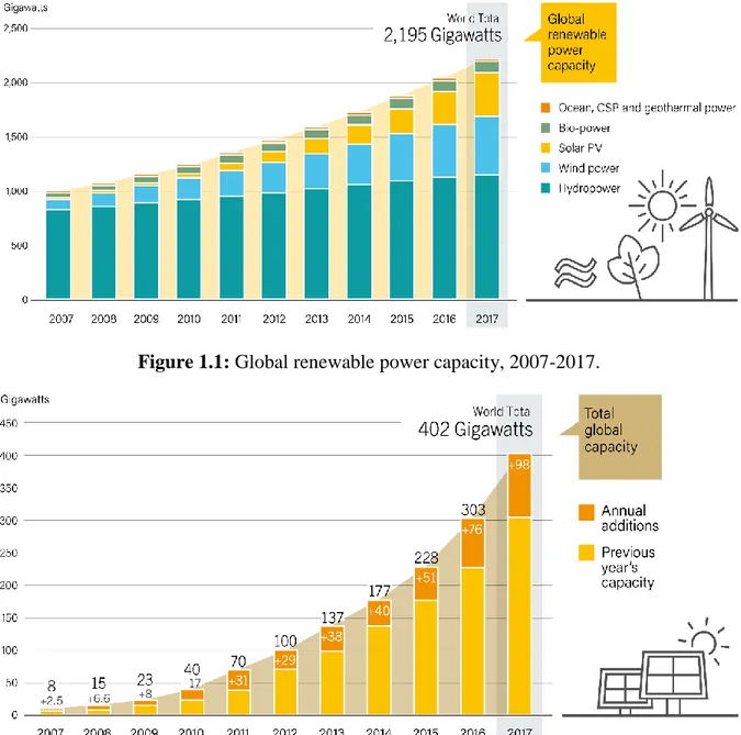
Solar energy through PV array systems is one of the most commonly used from renewable power sources. Where, a latest statistic study [4] shows the exponential increase in PV global capacity beside to wind global capacity from 2007 to 2017 in the world compared to other renewable sources as illustrated in Figure 1.1. The world solar PV global capacity increased exponentially from 8 GW in 2007 to 402 GW in 2017. While, the annual additions are increased from 2.5 GW in 2007 to 98 GW in 2017 as shown in Figure 1.2. For that, the solar PV global capacity would reach 1100 GW by 2030, according to the European Photovoltaic Industry Association (EPIA) [5].
This exceptional growth in PV arrays utilization is due to the cost reduction of PV modules and the introduction of economic incentives or subsidies. Moreover, PV arrays can range it easily as small scale for low power systems (individual utilizations) or large scale for high power systems, compared to other renewable energy sources that have higher costs [6]. According to the connection into the public grid, the PV systems can be divided in two categories: stand-alone PV systems and grid-connected PV systems.
2
Figure 1.1: Global renewable power capacity, 2007-2017.
Figure 1.2: Solar PV global capacity and annual additions, 2007-2017.
1.1.1STAND ALONE PV SYSTEMS
Stand-alone PV systems or namely Off-grid PV systems, are designed to function independently of the public grid [7-9]. These systems are contained of several components (PV arrays, power converters, storage components) that convert solar energy into electric energy and then delivered it to supply a DC or AC loads or to the storage system. For remote or isolated regions that are far from the conventional sources, stand-alone PV systems have been considered as a good alternative solution for meeting electricity demands where utility power is costly or unavailable. Stand-alone PV systems found numerous applications such as solar home systems (SHS), water pumping system in domestic, livestock water supplies, small-scale irrigation systems and fish farms [7-9].
3
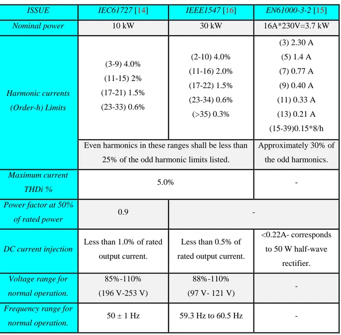
Grid-connected PV systems are designed to be able to inject the extracted PV power into the public grid. These systems are contained numerous power conversion stages (power converters) that used to extract the power from PV array and then inject it into the public grid [10-13]. The aims of these systems are to feed the grid-connected customer or offer bulk power in order to reduce fuel sources dependency and greenhouse gases. Also, the injection of power into grid should follow the standards given by the utility companies. Power quality, detection of islanding operation, grounding, etc. are the issues deal by these standards. The international standard IEC61727 [14], EN61000-3-2 [15] and IEEE1547 [16] standards are summarized and listed in Table I [17].
TABLE 1.1: Summary of the most interesting standards dealing with interconnections of PV
systems to the grid.
ISSUE IEC61727 [14] IEEE1547 [16] EN61000-3-2 [15]
Nominal power 10 kW 30 kW 16A*230V=3.7 kW
Harmonic currents (Order-h) Limits (3-9) 4.0% (11-15) 2% (17-21) 1.5% (23-33) 0.6% (2-10) 4.0% (11-16) 2.0% (17-22) 1.5% (23-34) 0.6% (>35) 0.3% (3) 2.30 A (5) 1.4 A (7) 0.77 A (9) 0.40 A (11) 0.33 A (13) 0.21 A (15-39)0.15*8/h Even harmonics in these ranges shall be less than
25% of the odd harmonic limits listed.
Approximately 30% of the odd harmonics.
Maximum current
THDi % 5.0% -
Power factor at 50%
of rated power 0.9 -
DC current injection Less than 1.0% of rated
output current.
Less than 0.5% of rated output current.
<0.22A- corresponds to 50 W half-wave
rectifier.
Voltage range for normal operation.
85%-110% (196 V-253 V)
88%-110%
(97 V- 121 V) -
Frequency range for
4
The main electrical components in grid-connected PV systems are the PV arrays and power electronic converters in addition to the grid-side filter. The key to improve the efficiency of PV arrays and assure the injection of the produced PV power into the grid with high quality is power electronic conversion. These systems are classified depending on the number of conversion stage into two categories single and dual-stages [18]. These categories commonly used power electronic topologies in PV systems.
1.2.1SINGLE-STAGE GRID CONNECTED PV SYSTEM
Single-stage grid-connected PV system as its name implies, contain only one conversion stage as described in Figure 1.3. This conversion stage is a DC-AC converter which used to extract the maximum power from PV arrays and inject it into the grid at the same time. The utilization of minimum number of conversion stage in this topology reduced weight, volume and cost [17]. To implement this topology practically and assure the injection of produced PV power, the input voltage of the inverter (output PV voltage) must be higher than the grid peak voltage. This reason requires choosing one of the two methods:
Employ a step-up transformer after the inverter in order to achieve a grid-connection with low grid peak voltage [19].
Connect large number of PV modules as string of series in order to achieve a PV array with sufficiently high PV voltage [20].
These methods are practically realized. But the adding of transformer in conversion chain will increase the volume, weight and cost of the system, besides increase the losses [21]. On the other hand, the connection of large number of PV modules suffers from several drawbacks such as hot-spots during partial shading of the PV array, reduced safety and increased probability of leakage current through the parasitic capacitance between the panel and the system ground. Furthermore, the control design in both methods is complicated due to the MPPT must be added with inverter control [21].
5
Figure 1.3: Single-stage grid-connected PV system topology.
1.2.2 DUAL-STAGE GRID CONNECTED PV SYSTEM
Dual-stage grid-connected PV system contains two conversion stages as described in Figure 1.4. The first stage is a DC-DC converter (generally boost converter) used to track the maximum power point (MPP). While, the second stage is a DC-AC converter (inverter) used to inject the extracted PV power from the first stage into the grid. The weight, volume and cost of this topology are high in comparison with single-stage topology [18]. Also, the losses in the conversion chain are increased due to the increase in number of components. However, it has been widely used due the fact that, the maximum power point tracking (MPPT) and current injection controls are decoupled at different converters which simplify the control design and achieve high harvesting energy capability. As well as, it provides the capacity to boost the DC-link voltage value above the grid voltage peak value whatever the PV modules connection and quantity of produced PV power [10].
6
1.2.3 OTHER TOPOLOGIES
Several grid-connected PV system topologies are developed based on single and dual-stage topologies in medium and high power range. Multi-string inverters and multi maximum power point trackers with centralized inverter are the most used topologies [22-24].
Multi-string inverters topology is shown in Figure 1.5. In this topology, the large PV array is divided into several single string of PV modules, each one connected to their inverter. All the inverters are connected to the grid through an inductive filter. This topology suffers from the same drawbacks of single-stage topology [24].
The multi maximum power point trackers with centralized inverter topology is composed of two conversion stages as shown in Figure 1.6, the first stage contains number of PV modules, each one connected to an individual DC-DC converter. In the second stage, a centralized inverter tied to the grid is used. Each output of the DC-DC converter is connected to the input of the centralized inverter. This topology offers the same advantages as the dual-stage topology. However, it requires a high cost [22].
Figure 1.5: Multi-string inverters topology.
In medium and high power range, the use of two-level inverter in these topologies require the operation at low switching frequency which creates many disadvantages such as large ripple, high values for grid-side filter, and rich harmonic content of the output voltage and
7
[26]. Where, the cascaded modular multilevel converters are suitable to modify the first topology. On the other hand, multilevel Neutral Point Clamped (NPC) inverters are proper to employ as centralized inverter. NPC inverters use the semiconductor switches connected in series, which allow the operation at higher DC voltages [27].
Figure 1.6: Multi MPPTs with centralized inverter topology.
1.3
D
ISSERTATION MOTIVATION AND OBJECTIVESThe selection of suitable grid-connected PV system topology and design of effective control schemes are considered as great challenges. It is necessary to select the suitable topology depending on the quantity of power injected into the grid in addition to the offers provided by topology advantages in term of energy harvesting capability. On the other hand, the development of effective controllers is crucial due to the effect of different operating conditions on the overall selected topology. So,this dissertation has two research directions which are: investigate sustainable grid-connected PV system topologies; and design effective control schemes.
1.3.1 INVESTIGATION OF SUSTAINABLE GRID-TIED PV SYSTEM TOPOLOGIES
As detailed in background of grid-connected PV system topologies section, the selection of single-stage grid-connected PV system suffers from several drawbacks especially in term of
8
advantages of applying dual-stage configuration in low power PV systems.
Then, the advantages of this configuration are combined with efficient grid-side multilevel converters in order to inject the produced PV power with high performance as well as assure the operation in medium and high power range.
The connection of PV modules as large PV array suffers from partial shading problem which reduce the effective energy harvesting and complicate the control design [21]. Also,due to high switching frequency provided by MPPT unit, DC-DC converter components do not support high power range. In order to overcome these problems, another objective of this dissertation is to investigate a topology that divides the large PV array to string modules with individual DC-DC converter and connects them to a centralized multilevel inverter.
1.3.2 INVESTIGATION OF EFFECTIVE CONTROL SCHEMES
Generally, the control scheme for the grid-connected PV systems is divided into three control steps, maximum power point tracking (MPPT), DC-link regulation and control of power injected into the grid.These control techniques have been investigated in several research and considered as an ongoing research topic.
PV arrays still do not provide a maximum efficiency, since their characteristics are highly nonlinear and are affected by climatic conditions. The random changes of these conditions reduce the PV array output power [3, 18]. Therefore, it is necessary to design a controller that is able to force the PV systems to continuously pursuing and rapidly extracting the maximum power from PV arrays under climatic condition changes [18].
Numerous MPPT techniques have been proposed in the literature; nevertheless, most of those techniques have certain drawbacks such as loss of tracking direction, low tracking speed and large oscillations. MPPT techniques that overcome those problems suffer from computational burden and increase the implementation costs [9].
For this reason, the first objective among the control schemes objectives in this dissertation focuses on the design of modified MPPT techniques that provide high performance tracking under atmospheric condition changes and simple to be implemented practically.
On the other hand, the produced PV power should be injected by using a second conversion stage (DC-AC converter) into the grid with minimum total harmonic distortions THDi% in grid currents under all atmospheric level conditions. This control step aims to achieve a good
DC-9 accurate power control and low THDi%.
Besides to employ the two-level inverter as a second conversion stage, different NPC multilevel inverters employed for the same reason due to inject a high quantity of produced power into the grid. The multilevel NPC inverters suffer from the unbalancing capacitor potential of DC-Link voltage, complexity of design and hard implementation of the control scheme [28].
The most conventional control schemes used for the second stage, employ cascaded linear PI regulators and pulse width or space vector modulation stage (PWM/SVM). The advantage provided by using the conventional control scheme based on PWM/SVM is to guarantee the operation at fixed switching frequency [23]. However, the switching frequency operation at high and medium power rang should be lower in order to minimize switching losses. Due to this condition, the conventional control schemes suffer from several drawbacks such as:
Inaccurate power control, in addition to significant lower order harmonics which degrade the quality of grid current [23].
The slow regulation of PI regulators and low-bandwidth modulation stage causes a slow transient response [23].
The grid voltage harmonics and control delay degrade the performance [23].
Moreover, the design of conventional control schemes is complicated in case of employing multilevel inverter in grid-connected systems because one must include DC-link capacitor voltages balancing into consideration [28-29].
Nowadays, Finite-control set model predictive control (FCS-MPC) is widely engaged in power electronics converters control due to its simplicity in experimental implementation and control design [30-32]. FCS-MPC remove the PI controllers and modulation stage. Moreover, it offers the abilityto include nonlinearities and constraints in the design of the controller. In PV system applications, FCS-MPC has been emerged for different PV systems such as: stand-alone systems [33], grid-connected PV systems [34-35]. As presented in [30-35], whatever the purposes which the FCS-MPC has been applied for them, a high performance control is achieved in comparison to the conventional methods. From that, FCS-MPC is considered as a best choice to control the second stage. Although, this technique suffers from two essential problems which are variable inherent switching frequency in addition to computational burden especially in case of high-level inverters.
10
in order to design an effective controller for the second conversion stage that provide high performance control under several atmospheric conditions.
1.4
D
ISSERTATIONO
RGANIZATIONThis dissertation is planned into six chapters. The work performed in each chapter is summarized as follows:
Chapter-2:
This chapter reviews the most widely employed control techniques for dual-stage grid-connected PV system. Where, maximum power point algorithms for photovoltaic systems are presented in the first part of this chapter. While, a short overview about DC-link voltage regulation techniques and control techniques of three-phase grid-connected systems are described in the second and third parts of this chapter respectively.
Chapter-3:
An improved control strategy based on fixed switching predictive control strategy for three phase dual-stage grid-connected PV system is proposed in this chapter. A variable incremental current step size of an MPPT current oriented loop based on fixed switching predictive current control is proposed and employed to control the first stage. While, a modified VOC based on predictive control strategy is introduced to control the second stage. The efficiency of the proposed control strategy is tested under sudden irradiation and reactive power changes demanded by the grid operator through numerical simulations and real-time HIL implementations.
Chapter-4:
In this chapter, high-level NPC inverters are employed in grid-connected PV system in order to inject the high produced PV power into the grid with high grid current quality.
Moreover, a simple and effective model predictive control (MPC) algorithm is proposed for grid-connected PV system using high-level NPC inverter (six-level) that permits to inject the active power generated by the PV system, the reactive power demanded by the grid operator and assure the balance of DC-link capacitor voltages.
11
same performance control provided by the first MPC algorithm with a significant reduction in computational burden.
The effectiveness of the proposed MPC and O-MPC are tested and compared through numerical simulations and real-time HIL implementations.
Chapter-5:
Chapter five proposes simple and effective controllers for large-scale PV system using NPC multilevel based on finite control set model predictive control (FCS-MPC) strategy.
The studied system is composed of two conversion stages, the first stage contains four PV arrays, each one connected to an individual DC-DC converter (boost converter). In the second stage, a five level NPC inverter tied to the grid is employed. Each DC-Link capacitor input of the NPC inverter is connected to the output of the DC-DC boost converter.
A voltage oriented maximum power point tracking (VO-MPPT) performed by FCS-MPCC is applied for each boost converter to draw the maximum power point from each PV array. In addition, an FCS-MPC controller is proposed to control the centralized five-level NPC inverter connected to the grid.
The proposed control scheme is evaluated versus the conventional control scheme based on PI regulators through Matlab/Simulink and Simpower packages simulations.
Chapter-6:
The thesis general conclusion and the author’s contributions are summarized in this chapter. In addition, possible extensions to the research presented in this thesis are suggested.
12
Chapter 2
Review of Control Techniques for
Dual-Stage Grid-Connected
PV System
2.1
I
NTRODUCTIONGrid connected PV systems have been used to inject the produced power from the PV arrays into the public grid [10-12]. The present challenge of these systems is to extract the maximum power from the PV arrays and deliver it to the grid with high grid current quality under climatic changes. As detailed in chapter 1, dual- stage grid-connected PV system topology offers an important advantage. This one eases the MPP tracking as well as boosts the DC-link voltage value above the grid peak voltage value whatever the produced PV power [10]. During the last decades, many research works have proposed several control schemes, which can be employed for dual-stage grid-connected PV system topology in order to increase its conversion efficiency [10-12]. These controls schemes are divided into three control steps, maximum power point tracking (MPPT), DC-link regulation and control of power injected into the grid.
In this chapter, a review of the most widely employed control techniques for dual-stage grid-connected PV system is presented. Maximum power point algorithms for photovoltaic systems is presented and compared in the first part of this chapter. While, short overviews about DC-link voltage regulation techniques and control techniques of three-phase grid-connected systems are described respectively in the second and third part of this chapter.
2.2
M
AXIMUM POWER POINT TRACKINGPV arrays still do not provide a maximum efficiency, since their characteristics are highly nonlinear and are affected by climatic conditions. The random changes of these conditions
13
able to force the PV systems to continuously pursuing and rapidly extracting the maximum power from PV arrays under climatic condition changes [18]. This controller is namely the maximum power point tracking (MPPT) controller that is employed in the first conversion stage (DC-DC converter). In this section, the most used MPPT algorithms are described and compared. This overview includes perturb and observe (P&O) algorithm, incremental conductance (INC) algorithm, advanced MPPT algorithm based on artificial intelligence, Current-oriented MPPT, Voltage-oriented MPPT.
2.2.1 PERTURB AND OBSERVE (P&O) ALGORITHM
This algorithm is designed depending on PV array behaviours. Where, voltage-current-power curve are scanned in order to find maximum voltage-current-power point (MPP). To be nearer to the MPP, if the operating power point is on the left side of the MPP, the algorithm moves it to the right by increasing the power converter duty cycle of the first conversion stage (DC-DC converter), and vice versa when the operating point is on the right side. Figure 3.2 (a) presents the basic flowchart of the P&O algorithm [36-39]. This MPPT algorithm is simple, easy to be implemented practically, and its cost is low. However, it suffers from slow and inaccurate convergence to the MPP under sudden irradiation change, as well as large power oscillation at steady state operation, which causes system power losses.
14
Also, the incremental conductance algorithm (INC) as P&O algorithm is also designed depending on the PV array behaviours. The identification of the instantaneous position to the MPP is determined based on the slope of the PV power curve; zero at the MPP, positive on the right-hand side of the MPP and negative on the left-hand side of the MPP. The basic equations of this algorithm are given as follows [40-41]:
0 pv pv dp dv at MPP (2.1) 0 pv pv dp dv at left of MPP (2.2) 0 pv pv dp dv at right of MPP (2.3) Since pv ( pv* pv) pv pv pv pv pv pv dp d v i di v i dv dv dv (2.4) Equation (2.4) can be expressed as:
pv pv pv pv di i dv v at left of the MPP (2.5) pv pv pv pv di i dv v at right of the MPP (2.6) pv pv pv pv di i dv v at the MPP (2.7) The goal is to adjust the power converter duty cycle to reach the MPP by comparison of the instantaneous conductance (I/V) with incremental conductance (∆I/∆V) [40-41]. The basic flowchart of the INC algorithm is illustrated in Figure 3.2(a).
The MPP is difficult to be obtained by Equation 2.7 in practical implementation due to the noise. In addition, The INC algorithm has the same advantages and disadvantages as the P&O algorithm.
15
Figure 2.2: Flowchart of the INC algorithm.
2.2.3ADVANCED MPPT ALGORITHM BASED ON ARTIFICIAL INTELLIGENCE
To overcome the drawbacks of P&O and INC algorithms, several recent research works have been investigated to introduce the artificial intelligence (AI) such as fuzzy logic control (FLC) [42-43] and neural networks (NN) [44-45], neuro-fuzzy networks (NFIS) [46-47], genetic algorithm (GA) [48-49], particle swarm optimization (PSO) [50-51]. The IA-MPPT methods offer high performance operation in terms of stability and response time. However, the implementation of these MPPTs is limited in real time because it requires a high computational burden and large memory.
2.2.4VOLTAGE- ORIENTED MPPT
The Voltage-oriented MPPT method consists of MPPT voltage-based algorithm (V-MPPT) in cascade with voltage controller as illustrated in Figure 2.3. the objective of V-MPPT is to deliver the reference voltage that represents the MPP voltage. While, the voltage controller aims to enforce the output PV voltage to track the reference voltage generated by the V-MPPT [ 52-53].
16
Besides, the voltage regulator is performed usually by a simple PI controller [53]. Nevertheless, the application of PI controller provides some drawbacks which affects MPP tracking such as: long response time, large overshoot and significant voltage ripples during steady-state operation [54-55]. For these reasons, sliding mode control (SMC) [54-55], andbackstepping control [56] have been investigated in order to design a voltage controller characterized by high control operations.
Figure 2.3: Diagram of voltage-oriented MPPT method.
17
Figure 2.5: Flowchart of the V-INC algorithm.
Because PV voltage corresponding the MPP changes slightly under sudden irradiation changes, VO-MPPT provides a fast MPP tracking. But it has low accuracy tracking. Moreover, the efficiency of this method depends on the voltage controller concept [55].
2.2.5CURRENT-ORIENTED MPPT
Figure 2.6 presents the basic concept of current- oriented MPPT. This MPPT involves MPPT current-based algorithm (C-MPPT) in cascade with current controller. The C-MPPT aims to generate the reference current that represents the MPP current, while the current controller aims to enforce the output PV current to track the reference current delivered by the C-MPPT [ 57-60].
Generally, the P&O and INC algorithms presented in Figure 2.7 and 2.8 are the most employed for this reason. The PI controller [57], the predictive current controller [58-59] and sliding mode current controller (SMCC) [60] are among the most useful techniques as current controller in this method. Predictive current controller besides to Sliding mode current controller has significant advantages such as robustness and implementation simplicity. Also, it has a good performance operation (fast response and very low current ripple) compared to PI
18
Figure 2.6: Diagram of Current-oriented MPPT method.
Figure 2.7: Flowchart of the C-P&O algorithm.
The CO-MPPT provides an accurate MPP tracking as well as a satisfactory oscillation reduction around the MPP, owing to the linear relation between the PV array current and solar irradiation. Nevertheless, it has a slow response time under sudden irradiation changes.
19
Figure 2.8: Flowchart of the C-INC algorithm.
Table 2.1 MPPT techniques comparison.
P&O [36-39] INC [40-41] AI-MPPT [42-51] VO-MPPT [52-53] CO-MPPT [57-60] Tracking speed
time Low Low High High Low
Tracking accuracy
Bad Bad Good Bad Very-good
Power
oscillation Large Large Very-small Small Small
Implementation
complexity Lower Lower Very-Higher Lower Lower
Power
20
Regarding the research results offered in the literature, a comparison between the previous MPPT techniques is summarized in Table 2.1. This comparison is carried out in terms of tracking speed time, tracking accuracy, power oscillation, implementation complexity and power efficiency.
2.3
DC-L
INK CONTROLThe first conversion stage extracts the PV power from the PV arrays to feed DC-link. The objective at this level is to regulate the DC-link voltage to the set reference value and estimate theamplitude of grid currents. To ensure a proper power injection control, the value of DC-link voltage reference must be choose higher than the grid peak voltage. The block diagram of DC-link voltage control is depicted in Figure 2.9. A simple PI regulator is mostly used in the industrial applications [61-62]. However, it has long time response, large overshoot and significant voltage ripples during steady-state operation. Several controllers that overcome these problems are presented in this section.
Figure 2.9: Diagram of DC-link voltage controller.
2.3.1DC-LINK CONTROLLERS BASED ON ARTIFICIAL INTELLIGENCE
Several research works have employed the artificial intelligence (AI) such as fuzzy logic control (FLC) [63] and, neuro-fuzzy networks (NFIS) [64], and particle swarm optimization (PSO) [65] to design an effective DC-link controller. These types of controllers overcome the drawbacks presented by PI regulator. But, the implementation of these controllers requires a high computational burden and large capacity of the memory. For this reason, the application of these controllers is limited especially in the complicated systems.
21
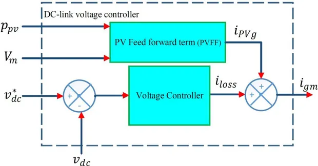
The block diagram of this controller is illustrated in Figure 2.10. The grid current consists of two terms, the first term is the contribution current by the PV array while the second one is the current losses [36, 66].
*
gm PVg loss
i i i (2.8) The contribution current by the PV array is given as
2 3 pv PVg m P i V (2.9)
Whereas, the difference between the measured 𝑉𝑑𝑐 and the reference 𝑉𝑑𝑐∗ is passed through a simple PI regulator in order to estimate the loss current [36, 66].
Figure 2.10: Diagram of DC-link voltage controller with feed forward term.
This controller provides a fast response time and low voltage ripple in steady-state operation under irradiation changes. Moreover, the hardware implementation of this type of controller is easy which makes it a best choice for the complicated systems.
2.3.3OTHER DC-LINK VOLTAGE CONTROLLERS
Recently, other control theories have been introduced to design new DC-link voltage controllers such as sliding mode theory [67] and integral sliding mode theory [68]. These controllers provide high performance operations under irradiation changes. Also,the hardware implementation of this type of controllers is easy. For these reasons, the application of these control theories is considered as an ongoing research topic.
22
This section discusses the control issues employed for grid tied voltage source converter (VSI) in PV systems. Different control structures such as direct power control (DPC), voltage oriented control (VOC) in stationary frame and synchronous frame, and model predictive control are presented and discussed. Moreover, the description of these control structures is summarized in order to perform a brief comparison.
2.4.1 DIRECT POWER CONTROL BASED ON SWITCHING TABLE (DPC)
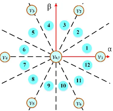
The objective of the DPC scheme is to regulate the grid powers to their references and to achieve low total harmonics distortions. The active power reference is estimated from DC-link voltage controller, while the reactive power reference is given by the grid operator. The functionality of this control schemes depends on the selection of switching state that minimize the error between the measured powers and their references. This selection is carried out using a predefined switching table. As indicated in Table. 2.2, The switching table is designed by dividing the plane α-β into twelve sectors Sx as shown in Figure 2.11 using the angular position
of the vector of grid voltage obtained from the PLL. Also, from the error Sd and Sq between the
references and the measured values of the active and reactive powers, obtained through two comparators with hysteresis band [69]. The scheme of DPC based on switching table is presented in Figure 2.12.
23 𝑆𝑑 𝑆𝑞 𝑆1 𝑆2 𝑆3 𝑆4 𝑆5 𝑆6 𝑆7 𝑆8 𝑆9 𝑆10 𝑆11 𝑆12 1 0 𝑣6 𝑣7 𝑣1 𝑣0 𝑣2 𝑣7 𝑣3 𝑣0 𝑣4 𝑣7 𝑣5 𝑣0 1 𝑣7 𝑣7 𝑣0 𝑣0 𝑣7 𝑣7 𝑣0 𝑣0 𝑣7 𝑣7 𝑣0 𝑣0 0 0 𝑣6 𝑣1 𝑣1 𝑣2 𝑣2 𝑣3 𝑣3 𝑣4 𝑣4 𝑣5 𝑣5 𝑣6 1 𝑣1 𝑣2 𝑣2 𝑣3 𝑣3 𝑣4 𝑣4 𝑣5 𝑣5 𝑣6 𝑣6 𝑣1 𝑣0(0 0 0), 𝑣1(1 0 0), 𝑣2(1 1 0), 𝑣3(0 1 0), 𝑣4(0 1 1), 𝑣5(0 0 1), 𝑣6(1 0 1), 𝑣0(1 1 1)
Figure 2.12: Direct power control (DPC) scheme.
The DPC scheme is easy to be implemented practically. But, it has slow response time and significant lower order harmonics. Furthermore, it operates with variable switching frequency.
2.4.2STATIONARY FRAME VOC
The scheme of stationary frame is presented in Figure 2.13. The objective of this control scheme is to achieve a sinusoidal form of grid currents with low total harmonics distortions. In this scheme, the DC-link voltage controller estimates the peak of grid current reference igm.
24
the first harmonic of the grid voltages used for calculating the unitary waveforms. The current igm is multiplied by grid unitary waveforms in order to obtain three phase grid current references
and transformed it to αβ frame. Also, the measured grid currents are transferred to stationary frame and compared with their reference’s values. Then, two PI regulators are used to generate the reference voltage that will be given to the modulation stage [70].
The stationary frame VOC scheme guarantees the operation at fixed switching frequency. Also, it is easy to be implemented practically. But, it has slow response time and significant lower order harmonics [30].
Figure 2.13: Stationary frame VOC scheme.
2.4.3SYNCHRONOUS FRAME VOC
The scheme shown in Figure 2.14 represents the synchronous frame VOC. This control scheme aims to regulate the grid current id-iq over their references. The reference current id is
estimated by DC-link voltage controller while the iq reference current is estimated from the
reactive power requested by the grid operator.
The measured grid currents are transformed from natural frame (abc) to rotating frame and their values id-iq are compared with their reference’s values. Then, PI-based controllers generate
the reference d and q components of the reference voltage that will be given to the modulation stage after transfer it to αβ frame [70].
25
fixed switching frequency and easy to be implemented practically. However, it has slow response time, large current fluctuation and significant lower order harmonics [28].
Figure 2.14: Synchronous Frame VOC scheme.
2.4.4 FINITE CONTROL SET MODEL PREDICTIVE CONTROL FOR VOLTAGE SOURCE CONVERTER TIED TO THE GRID
In recent research, the finite-control set model predictive control (FCS-MPC) has been applied in many power electronics applications [30-32]. This due to the power electronic converter that contains finite number of switching states, for example eight switching states are available for two levels VSI. In grid connected systems, FCS-MPC method has been employed for different control purposes such as synchronous grid current control [30], d-q rotating frame grid current control [30] and power control [32].From the references and measured variables and by using the discrete time model of VSI tied to the network, the functionality of FCS-MPC is based on prediction of the future behavior of state variables for all possible switching states and compare them using a cost function. The optimal switching that minimizes the cost function is selected and applied for the VSI during the next sampling time. The scheme and flowchart presented respectively in Figure 2.15 and 16 summarize the functionality of FCS-MPC. Compared to the classical control techniques, FCS-MPC eliminates the need for linear PI regulators and modulation stage. Furthermore, it provides high performance operation. The main features and challenges of the FCS-MPC are summarized as follows [28]:
26
The concept of FCS-MPC is simple and easy to understand
Uses the inherent discrete nature of the VSI connected to the grid which makes it easy to be implemented using the industry standard digital control platforms.
The ability to add nonlinearities and constraints in the design of the controller
Optimizations are greatly simplified due to finite number of switching states generated by VSI.
Figure 2.15: Finite control-set model predictive control (FCS-MPC) scheme.
Drawbacks of FCS-MPC:
Needs a high computational burden
Operates with the variable switching frequency
Estimation of weighting factor values is not analytical or numerical
Degradation of control performance if the system model and prediction horizon is not formulated properly.
The first challenge is investigated carefully in this dissertation. While, a solution to reduce the computational burden has been developed to promote the FCS-MPC strategy as the next generation high performance control tool for multilevel VSI.
27
Figure 2.16 Flowchart of finite control set model predictive control (FCS-MPC).
2.4.5COMPARISON OF FCS-MPC WITH CONVENTIONAL CONTROL SCHEMES
In this section, a comparison between FCS-MPC strategy and the conventional strategies is performed based on the research results offered in the literature. This comparison is
28
recommends that the FCS-MPC strategy is an intuitive and powerful tool to control the grid tied VSI systems compared to the other conventional methods. Nevertheless, FCS-MPC strategy has some drawbacks such as variable switching frequency and high computational burden.
Table 2.3 Comparison between conventional control schemes and FCS-MPC.
Description
linear control based on PI/modulator [70] DPC based on switching table [69] FCS-MPC [30-32]
Control diagram Fig. 2.14 Fig. 2.12 Fig. 2.15
Model
-Linear load model for PI
-Inverter model for SVM
- - Discrete-time model of the complete system
Controller design
PI adjustment (root locus) + Modulator
design
Design of lookup table Cost function definition
Nature of controller Linear Nonlinear Nonlinear
Implementation
platform Analog or digital Digital Digital
Modulation PWM/SVM/SHE Not required Not required
Switching frequency Fixed Variable Variable
(but controllable)
Multivariable Coupled Coupled Decoupled
Constraints inclusion Not possible Not possible easy to include
Complexity of concept High with SVM Simple and intuitive Simple and intuitive
Steady-state
performance Good in dq frame Bad
Good in abc, αβ and
dq frames
Transient
performance Moderate Moderate Excellent
Computational
burden High with SVM low High
Robustness of
controller Poor Poor Excellent
29
A review of the most widely employed control techniques for dual-stage grid-connected PV system is presented in this chapter. Several maximum power point algorithms for photovoltaic systems are presented and compared in the first part of this chapter. The advantages and disadvantages related to different MPPT algorithms in terms of response time, tracking accuracy, power oscillations, and computational burden are discussed. Furthermore, the state-of-the-art of the DC-link voltage controllers are reviewed and compared regarding quality of the performance operation, easy design and implementation simplicity. Also, control schemes of three-phase VSI grid-connected systems are described in the third part of this chapter. The analysis presented in this chapter favors the voltage oriented MPPT, current oriented MPPT and the FCS-MPC strategy as the next generation control tool to achieve high performance operation for the grid-connected PV systems
30
Chapter 3
Improved Control of Three Phase
Dual-Stage Grid Connected
PV System Based on
a Predictive Control Strategy
3.1
I
NTRODUCTIONThe conventional control strategies of dual-stage grid-connected PV system suffer from several drawbacks such as: bad MPPT tracking, inaccurate grid power control, low grid current quality, hard implementation practically and variable switching frequency as detailed in the previous chapter. Therefore, an improved control strategy based on fixed switching predictive control strategy for three-phase dual-stage grid-connected PV system is proposed in this chapter. A variable incremental current step size of an MPPT current oriented loop based on fixed switching predictive current control is proposed and employed to control the first stage in order to improve the performance in terms of MPP tracking accuracy, dynamic response speed and oscillation reduction at the MPP. While, the second contribution proposed in this chapter is about the control of second stage. A predictive control strategy is introduced with space vector modulation (SVM) to modify voltage oriented control (VOC) strategy. The proposed PS-VOC aims to eliminate the PI regulators drawbacks as well as the control delay in order to generate the produced PV power and the reactive power demanded by the grid operator into the grid with high grid current quality.