HAL Id: hal-00569380
https://hal.archives-ouvertes.fr/hal-00569380
Submitted on 24 Feb 2011
HAL is a multi-disciplinary open access
archive for the deposit and dissemination of
sci-entific research documents, whether they are
pub-lished or not. The documents may come from
teaching and research institutions in France or
abroad, or from public or private research centers.
L’archive ouverte pluridisciplinaire HAL, est
destinée au dépôt et à la diffusion de documents
scientifiques de niveau recherche, publiés ou non,
émanant des établissements d’enseignement et de
recherche français ou étrangers, des laboratoires
publics ou privés.
Cascadability assessment of a
microcavity-saturable-absorber based phase-preserving
amplitude regenerator in a DPSK transmission system
Quang Trung Le, Laurent Bramerie, Mathilde Gay, Sebastien Lobo, Michel
Joindot, Jean-Claude Simon, Hoang Trung Nguyen, Jean-Louis Oudar
To cite this version:
Quang Trung Le, Laurent Bramerie, Mathilde Gay, Sebastien Lobo, Michel Joindot, et al..
Cascadabil-ity assessment of a microcavCascadabil-ity-saturable-absorber based phase-preserving amplitude regenerator in
a DPSK transmission system. 36th European Conference and Exhibition on Optical Communication
(ECOC), 2010, Sep 2010, Italy. pp.Mo.2.F.3, �10.1109/ECOC.2010.5621322�. �hal-00569380�
Cascadability Assessment of a Microcavity-Saturable-Absorber
based Phase-Preserving Amplitude Regenerator in a DPSK
transmission system
Quang Trung Le(1), Laurent Bramerie(1), Mathilde Gay(1), Sebastien Lobo(1), Michel Joindot(1),
Jean-Claude Simon(1), Hoang-Trung Nguyen(2), Jean-Louis Oudar(2)
(1) Universit ´e Europ ´eenne de Bretagne (UEB), CNRS-Foton laboratory (UMR 6082)/Universit ´e de
Rennes 1, Enssat, BP 80518, 22305 Lannion Cedex, France,B quang-trung.le@enssat.fr (2)LPN-CNRS, Route de Nozay, F-91460 Marcourssis, France,B jean-louis.oudar@lpn.cnrs.fr
Abstract We investigate the cascadability of a microcavity-saturable-absorber-based phase-preserving amplitude regenerator for RZ-DPSK signals. The results show that the tolerance of phase-encoded signals to nonlinear phase noise is increased. A distance improvement ratio up to 1.6 is experimentally demonstrated.
Introduction
The differential phase-shift keying (DPSK) mod-ulation format has recently attracted much at-tention for high-speed and ultra long-haul opti-cal transmission. It offers, for instance, a 3-dB improvement in receiver sensitivity compared to OOK (with balanced detection) and an enhanced tolerance to dispersion and nonlinear effects1.
All-optical regeneration that aims to enhance the signal quality would be attractive to improve the performance of DPSK systems. In the lit-erature, some interesting solutions for phase re-generation based on phase-sensitive interfero-metric techniques have been proposed2,3. How-ever, those techniques are rather complex, and have instability issues. Another approach con-sists in phase-preserving amplitude regeneration that can prevent the accumulation of nonlinear phase noise (NLPN) during transmission4. The
cascadability of the phase-preserving amplitude regenerators based on four-wave mixing in fibre5
and on nonlinear amplifier loop mirror6are
exper-imentally demonstrated in the literature. Both use shot-pulse RZ DPSK signals at 10 Gbit/s.
Recently, we have shown that a novel mi-crocavity saturable absorber (SA1)7 can provide
phase-preserving amplitude noise reduction, and therefore, can prevent from the accumulation of NLPN in a RZ DPSK transmission system8. The microcavity saturable absorber consists of a pas-sive nonlinear mirror which promises a simple, compact and WDM compatible solution9.
In this paper, we report on the cascadability assessment of the SA1 based phase-preserving amplitude regenerator in a recirculating loop us-ing conventional RZ33 DPSK at 42.7 Gbit/s. The numerical and experimental results demonstrate that the tolerance of phase-encoded signals to NLPN is considerably increased thanks to the
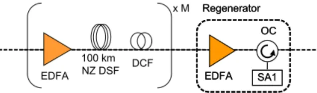
re-Regenerator OC SA1 EDFA Regenerator OC SA1 EDFA 100 km EDFA NZ DSF x M DCF
Fig. 1: Scheme of a regenerated transmission.
generator. An improvement of bit error rate and of transmission distance can be achieved.
Numerical simulation
For a complete regeneration of DPSK signals, both phase and amplitude regenerations are needed. However, we illustrate in this section that when SA1 based phase-preserving amplitude generators are used in the transmission line, a re-duction of SPM-induced NLPN at the receiver can be obtained. Indeed, by strongly reducing the am-plitude noise, the SA1 prevents the accumulation of NLPN in the next transmission spans.
The transmission link is modelled as the con-catenation of 100 km amplification spans com-posed of non-zero dispersion-shifted fibres (NZ DSF) followed by a dispersion-compensating-fiber (DCF) (Fig. 1). The NZ DSF has a disper-sion of 4.5 ps.nm−1.km−1, a nonlinear coefficient
of 2 W−1.km−1, and an attenuation of 0.23 dB/km. The total span loss is 26 dB, which is compen-sated for by an EDFA with noise figure of 4.5 dB. The chromatic dispersion is perfectly compen-sated, and the nonlinearities occur only in the transmission fibre. A phase-preserving amplitude regenerator based on SA1 is inserted every M spans.
The SA1 model is based on the same rate equation as for the classical saturable absorber10
but with an inverted sign of the last term (which is directly dependent on the input power) in order to obtain a decreasing reflectance in response to an
ECOC 2010, 19-23 September, 2010, Torino, Italy
978-1-4244-8535-2/10/$26.00 ©2010 IEEE
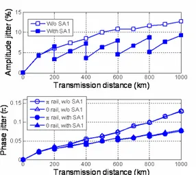
Fig. 2: Amplitude and phase jitter vs. transmission dis-tance with and without SA1.
Fig. 3: Phase Q-factor after 1000 km of transmission vs. fibre launched power.
increasing input power: dα(t, P ) dt = α0− α(t, P ) τ + αP τ Psat
P is the input power, α is the device’s ab-sorption, α0 is the small signal absorption, Psat
is the saturation power, and τ is the recovery time. The parameters used in the simulation are Psat=7 mW, τ =3.5 ps and α0=5.3, where d is the
total quantum-well section thickness. Those pa-rameters are representative of the investigated device for the experimental studies.
The rms variations of the amplitude and dif-ferential phase (on the zero and π rails) for RZ DPSK signals transmitted through the system in the cases with and without SA1-based ampli-tude regenerators are plotted in Fig. 2. The fi-bre launched power is set at 4 dBm. The regen-erators are located after every 200 km of trans-mission. As can be seen, in the absence of re-generators, both the amplitude and phase jitters increase continuously which can become critical for the system performance. In the case with re-generators, the amplitude noise is considerably reduced at each regenerator location. After the first regenerator, the slope of differential phase jitters with transmission distance is reduced. At 1000 km, the rms phase jitter is reduced by 40% compared to the non regenerated case.
3 nm Tx RZ DPSK ASE EDFA2 EDFA2 100 km NZ DSF PFibre EDFA3 EDFA3 OC EDFA1 EDFA1 AS1 Rx RZ DPSK ATT 5 nm Gain Equalizer Regenerator DCF
Fig. 4: Recirculating loop experiment of cascaded mi-crocavity-saturable-absorber-based regenerator.
As a qualitative estimate of the transmission performance of the system, we use here the dif-ferential phase Q-factor (defined as π divided by the sum of the rms variations of the differential phase between adjacent bits on the zero and π rails)11, which provides a measure of the phase
fluctuation in the signal. Fig. 3 shows the phase Q-factor in dB (20.log10(Q)) after 1000 km of transmission with and without SA1 versus fibre launched power. In the linear regime at low fibre launched power, the system performance is lim-ited by OSNR degradation. No improvement by the regenerator is observed, as it preserves the signal phase. At high fibre launched power, Q-factor is improved. An increase of nonlinear toler-ance is thus obtained thanks to the regenerator. This Q-factor margin can be used for increasing the transmission distance, which will be demon-strated experimentally in the next sections. Experimental setup
The experimental setup is shown in Fig. 4. The transmitter based on Mach-Zehnder modulators generates an 8-ps-pulse-width RZ DPSK signal at 42.7 Gbit/s. The signal wavelength is centred at 1550 nm. An ASE source followed by a 3-nm band-pass optical filter, followed by a variable op-tical attenuator (ATT) is used in order to modify the OSNR at the transmitter output.
The signal is boosted by EDFA1 before be-ing sent to SA1 via an optical circulator (OC). The transmission line consists of 100 km of non-zero dispersion-shifted fibre (NZ DSF) with chro-matic dispersion of 4.5 ps/km/nm at 1550 nm, fol-lowed by a dispersion-compensating fibre (DCF). EDFA2 increases the launched power up to 13 dBm, while EDFA3 compensates for the resid-ual loss. A gain eqresid-ualizer is required to compen-sate the signal spectrum distortion due to the de-vice’s resonance. The preamplified RZ DPSK re-ceiver consists of a fibre-based delay-line interfer-ometer (DLI) and a balanced detector.
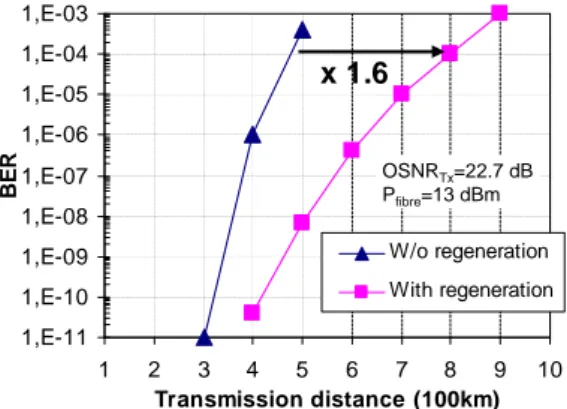
1,E-11 1,E-10 1,E-09 1,E-08 1,E-07 1,E-06 1,E-05 1,E-04 1,E-03 1 2 3 4 5 6 7 8 9 10 Transmission distance (100km) B E R W/o regeneration With regeneration x 1.6 OSNRTx=22.7 dB Pfibre=13 dBm
Fig. 5: BER vs. transmission distance.
Experimental results
Figure 5 shows the measured bit error rate (BER) versus transmission distance with and without SA1 based amplitude regeneration. The OSNR at the transmitter (called OSNRT x) is 22.7 dB (over
1 nm) and the fibre launched power is 13 dBm. This high value is unrealistic, but is required, in our experiment, to generate a high enough amount of NLPN in 100 km of transmission fibre. For longer distance between regenerators, the BER curves are shifted towards lower input power values since less launched power is needed for the same amount of total nonlinear phase noise in the system. In the case without SA1, the BER grows rapidly due to linear and nonlinear phase noise accumulation. When the phase-preserving amplitude regenerator is applied, the amplitude noise is reduced and the nonlinear phase noise is partly removed. As a consequence, the trans-mission distance is enhanced thanks to the re-generator. A transmission distance of 800 km is reached for a BER of 10−4 compared to 500 km
in the case without regeneration, a distance im-provement ratio of 1.6 is thus obtained.
We define the distance improvement ratio (DIR) as the ratio of distances covered with and with-out regeneration for a given BER. Fig. 6 presents the evolution of DIR versus OSNRT xfor a BER of
10−4 and with fibre launched powers of 10 dBm and 13 dBm. At the first glance, the results show that the DIR generally exceeds 1.2 for all OSNRT x values. As can be seen, a difference
in regeneration efficiency is shown when the fibre launched power varies from 10 dBm to 13 dBm. This can be explained by the fact that, at higher fibre launched power (13 dBm), the nonlinear effects that convert amplitude noise into phase noise are more efficient. Consequently, better regenerator efficiency is obtained (distance im-provement ratio of 1.4 to 1.6 compared to 1.2 at 10 dBm). The greater the fibre launched power, the more efficient the nonlinear effects, and the
1 1.1 1.2 1.3 1.4 1.5 1.6 1.7 13 15 17 19 21 23
Transmitter OSNR over 1 nm (dB)
D IR ( B E R = 1 0 -4 )
Fiber launched power 13dBm Fiber launched power 10dBm
Fig. 6: Distance improvement ratio at BER of 10−4with different fibre launched powers and transmitter OSNR.
better the distance improvement.
When OSNRT x increases the obtained DIR is
slightly better. For a fibre launched power of 13 dBm, a DIR of 1.4 is obtained at low OSNRT x
(13.8 dB), and this improvement ratio is 1.6 at high OSNRT x (22.7 dB). At a fibre launched
power of 10 dBm, this evolution is less visible be-cause the nonlinear effects are less efficient. Conclusions
Cascaded performance of a phase-preserving amplitude regenerator based on a microcavity saturable absorber has been numerically and ex-perimentally investigated in a RZ-DPSK transmis-sion system at 42.7 Gbit/s via a recirculating loop setup. The obtained results show that the regen-erator reduced the amplitude noise, which is the origin of nonlinear phase noise, thus improve the system performance. The best regenerator effi-ciency is achieved at high fibre launched power where the nonlinear effects are significant. A dis-tance improvement ratio up to 1.6 is experimen-tally obtained at bit error rate of 10−4.
References
1 A. Gnauck et al., J. Lightw. Technol., 23(1), 115–130, 2005.
2 K. Croussore et al., Proc. OFC’06, OFH7, 2006.
3 P. Devgan et al., Proc. OFC’05, PDP34, 2005. 4 S. Boscolo et al., IEEE J. Quantum Electron.,
42(7), 619–624, 2006.
5 M. Matsumoto., Proc. ECOC’06, 1.3.5, 2006. 6 C. Stephan et al., Proc. ECOC’09, 3.3.5, 2009. 7 H. T. Nguyen et al., Appl. Phys. Lett., 92,
111107, 2008.
8 Q. T. Le et al., Proc. OFC’10, OMT4, 2010. 9 L. Bramerie et al., Proc. OFC’07, PDP1, 2007. 10 H. Haus et al., J. Opt. Soc. Am. B, 2(7):1237–
1243, 1985.
11 C. Xu et al., J. Sel. Topics Quantum Electron., 10(2):281–293, 2004.