HAL Id: hal-00639095
https://hal.archives-ouvertes.fr/hal-00639095
Submitted on 8 Nov 2011
HAL is a multi-disciplinary open access
archive for the deposit and dissemination of sci-entific research documents, whether they are pub-lished or not. The documents may come from teaching and research institutions in France or abroad, or from public or private research centers.
L’archive ouverte pluridisciplinaire HAL, est destinée au dépôt et à la diffusion de documents scientifiques de niveau recherche, publiés ou non, émanant des établissements d’enseignement et de recherche français ou étrangers, des laboratoires publics ou privés.
Mario Lezoche
To cite this version:
Mario Lezoche. Explicitating semantics in Enterprise Information Systems Models. 2011. �hal-00639095�
Faculté de Sciences et Technologies
Ecole Doctorale IAEM Lorraine
UMR 7039 NANCY-UNIVERSITE CNRS UMR 7503 NANCY-UNIVERSITE CNRS
Rapport de Recherche
Présenté en vue de l’obtention du
Diplôme de Recherche Post Doctorale de l’Université Henri Poincaré, Nancy 1 par
Mario Lezoche
Docteur de l’Université Roma TRE (Italie)
Explicitating semantics in Enterprise Information Systems Models
Soutenance publique le 7 Novembre 2011 devant la commission d’examen : Membres du Jury :
Président du Jury : Thierry Divoux Professeur à l’Université Henri Poincaré – Nancy 1 Directeur de Travaux : Hervé Panetto Professeur à l’Université Henri Poincaré – Nancy 1
Encadrant : Alexis Aubry Maitre de Conférences à l’Université Henri Poincaré – Nancy 1 Examinateur : Nacer Boudjlida Professeur à l’Université Henri Poincaré – Nancy 1
Acknowledgement
This Post-Doctoral experience was firstly started under Interop VLab project and it was completed at the CRAN laboratory in the SYMPA team, SIO project, Université Henri Poincaré – Nancy 1 and at LORIA in the Score team. Therefore I would like to thank the CRAN laboratory director, Pr. Alain Richard, the SYMPA thematic manager, Pr. Thierry Divoux, the responsible of the SIO project, Pr. Benoit Iung, the LORIA director Françoise Simonot, the Score team manager Francois Charoy and Pr. Nacer Boudjlida, my guide in the Loria world, for welcoming me in such a warm way. I would like also to thank the Director of ESIAL School of engineering, Pr. André Schaff, who welcomed me during my pedagogic duties.
When I arrived in Nancy I found a weather that was quite different from that of my birth country. It was January and, I remember precisely, there were -18 Celsius degrees. I really hoped the people I would have met the next day would have been much warmer. My hopes were more than fulfilled. I am greatly attached to the concept of family and Life helped me letting meet people who became my new extended family.
Firstly, I would like to express my thankfulness to Professor Hervé Panetto who greeted me with an enormous smile. He guided me through the development of this research topic but also he let me acquire knowledge in different domains, better comprehension of research and pedagogic methodologies, involvement in laboratory and school life at all levels. It was really a diving experience in a new way to conceive this job, this passion. Our friendly relationship let me find the fire that warmed the cold distance to my family. I would like to thanks A/Professor Alexis Aubry, he is a special researcher and person. We had a lot of interesting and worthwhile discussions during this period and, from the moment we became roommates we deepened our knowledge and I find an all-accomplished person with whom I have many common interests. I like to thanks my colleague Esma Yahia for welcoming me in an enthusiastic way and for working hard together during all this time. Her feisty character
spurred me to always deepen the topics we discussed on. We rapidly became friends and knowing and helping each other made me feel at home.
Next to the core people teams, with whom I worked, there are all the laboratory people that enriched in an extraordinary way my work and private Nancy life. Pierre, Gabriela, Pascale and Chiara created a little family, my little Nancy family, who shared sadness and happiness, failures and victories… Life.
I would like to thanks all the other kind people of the laboratory and of the school who were always nice and wishful to help, David, William, Thomas, Alexandre, Fabien, Yongxin, Leila, Sylvain, Jéremy, Alex, Ludovic, Romain and all the other really kind people with whom I passed my time in and out the laboratory.
What I am living is a dream, one of my oldest dream, living an experience in a country I always wanted to know and performing a job I was eager to transform in my life.
The same life that changed three years ago when I met the person who transformed the way I felt my life. I would like, so, to thank my beloved Costanza who gave me the strength, the energy and a new perspective to look at the events, a new hope in our private spiritual road and who made me remember what the meaning of Life is.
1 INTRODUCTION ... 7
1.1 RESEARCH DOMAIN CONTEXT ... 7
2 COOPERATIVE INFORMATION SYSTEM ... 11
3 OUR APPROACH FOR SEMANTICS ENACTMENT IN CONCEPTUAL MODELS ... 15
3.1 STEP 1: REVERSE ENGINEERING ... 17
3.2 STEP 2: EXPERT KNOWLEDGE INJECTION ... 18
3.3 STEP 3: FACT-ORIENTED TRANSFORMATION ... 20
3.4 FOL REPRESENTATION ... 23
3.4.1 Translation of UML Artefacts and Semantic Annotations in FOL ... 24
1. UML artefacts ... 24
2. Semantic Annotation in Fact-Oriented Model ... 28
4 A SEMANTICS STRUCTURING PROCESS ... 31
4.1 CORE AND EXTENDED SEMANTICS ... 31
4.2 SOME MATHEMATICAL DEFINITIONS ... 32
4.3 SEMANTIC BLOCKS IDENTIFICATION ... 34
4.4 USING GRAPH THEORY FOR BUILDING SBCCI ... 38
4.5 A PROCEDURE TO COMPUTE THE SEMANTIC BLOCKS ... 40
5 CASE STUDY ... 45
5.1 CONCEPTUALISATION OF SAGE X3 ERP MODEL ... 45
5.2 SEMANTICS STRUCTURING OF FLEXNET MES MODEL ... 50
6 SEMANTIC ANNOTATION MODEL DEFINITION FOR SYSTEMS INTEROPERABILITY . 61 6.1 WHAT IS SEMANTIC ANNOTATION? ... 62
6.1.1 Semantic annotation ... 63
6.2 METAMODEL OF SEMANTIC ANNOTATION STRUCTURE MODEL ... 65
6.3 CONCLUSIONS ... 66 7 CONCLUSIONS ... 69 7.1 SCIENTIFIC CONTRIBUTION ... 69 8 REFERENCES ... 73 APPENDIX ... 83 9 APPENDIX A ... 84 10 APPENDIX B ... 99 11 APPENDIX C ... 118 12 APPENDIX D ... 130
1 Introduction
The present Post-Doctoral work was firstly financed with a grant offered by the University Henri Poincaré, Nancy I, and it was completed at the Research Centre for Automatic Control (Centre de Recherche en Automatique de Nancy - CRAN) in the Ambient Manufacturing System (SYMPA) team, Inter Operating System (SIO) project, and at the Lorraine Research Laboratory in Computer Science and its Applications (Laboratoire Lorrain de Recherche en Informatique et ses Applications – LORIA) in the Score team.
During this period, passed working as a researcher in these laboratories, I had the possibility to act as a teacher at the School of Engineering in Information Technology (“École Supérieure d’Informatique et Applications de Lorraine” - ESIAL). This experience helped me to better comprehend the different views of the research and teaching life.
1.1 Research domain context
In a present expanded market, enterprises are forced to become increasingly fast adapting and flexible in order to manage the rapid changing business conditions. Today’s challenges mainly concern Enterprise Interoperability (EI) that focuses on removing organisational barriers and improving different type of interaction between people, systems and companies. EI passes, mainly, through their Enterprise Information Systems (EISs). They involve large number of ISs distributed over large, complex networked architecture. Such cooperative enterprise information systems (CEIS) have access to a large amount of information and have to interoperate to achieve their purpose. CEIS architects and developers have to face a hard problem: interoperability.
Interoperability can be defined as the ability of two or more systems to share, to understand and to consume information (IEEE, 1990). The work (Chen et al., 2006) in the INTEROP NoE project has identified three different levels of barriers for interoperability: technical, conceptual and organisational. Organisational barriers are still an important issue but they are out of scope of this paper. The technological barriers are strongly studied by researchers
in computer science and they are, in general, addressed by the models transformation (Frankel, 2003).
Enterprise Modelling (EM) plays a critical role in this interoperability action, enabling the capture of all the information and knowledge relevant for the enterprise operations and organisation (Vernadat, 1996; Panetto and Molina, 2004). The produced Enterprise Models must contain the necessary and sufficient semantics in order to be intelligible and then enabling the global Enterprise Interoperability. While studying an Information System (IS) model, we observe that its semantics is scrambled, due to the implementation requirements, and, more important, it is tacit.
Our research focuses on the conceptual level of interoperability, namely the ability to understand the exchanged information. Information may be defined as data linked to knowledge about this data. It is represented by so-called concepts. A concept is a cognitive unit of meaning (Vyvyan, 2006), an abstract idea, a mental symbol. It is created in the activity of conceptualisation, that is, a general and abstract mental representation of an object. During the history of human effort to model knowledge, different conceptualisation approaches regarding different application domains were developed (Aspray, 1985).
This research memory will show the results obtained during the Post Doc study referring to the published works. It deals with a first phase from our general research work that focuses on the study of the semantic loss that appears in the exchange of information about business concepts. In order to quantify the semantic gap between interoperating ISs, their
semantics needs to be enacted and structured by enriching, normalising and analysing their conceptual models. We propose a conceptualisation approach for explicitation of the
finest-grained semantics, embedded into conceptual models in order to facilitate the semantic matching between two different information systems that have to interoperate. The structure of the document represents the different steps and the research domain on which the study focused.
In section 2, we present the general context of our work, namely cooperative enterprise information systems. The following section, the 3rd section proposes a knowledge
explicitation process that transforms implemented relational model to a fact-oriented conceptual one. This process allows us to discover the finest-grained semantics that must be enacted to study semantics interoperability between collaborating ISs. Then, we will define First Order Logic formalisations of UML artefacts (classes, attributes, associations).
In the 4th section, the semantics structuring method is described. It assumes the definition of semantic aggregates that highlight the structure of the embedded semantics in the conceptual model obtained after the conceptualisation process. Each semantic aggregate (namely, each semantic block) is associated with a concept and defines the minimal mandatory semantics attached to this concept.
In order to illustrate the proposed approach, a case study is also presented in the section 5. This case study deals with B2M (Business to Manufacturing) interoperability requirements between an Enterprise Resource Planning (ERP) system and a Manufacturing Execution System (MES) applications and consists in applying our approach in order to extract the semantics embedded into those ISs. In Section 6 new study on Semantic annotation structure and use is presented in order to better explicitate the tacit knowledge hidden in the Enterprise Models. Moreover, enriching this semantics is still an open issue; we can for example quote those researches made by (Boudjlida and Panetto, 2008) in terms of process models annotations.
In section 7 we will discuss about further works concerning using the resulting semantic conceptual model and architecture for facilitating the assessment of the (non)-interoperation barriers between Enterprise Information Systems or some of their subsystems (identified, for instance, by the semantic blocks) as suggested in (Yahia, 2011). The resulting analysis, based on an interoperability measures map, can help information technology consulting companies for parameterising and integrating enterprise applications (ERP, MES…) taking into account interoperability constraints. The Appendix, containing all the published research works, completes this report.
2 Cooperative Information System
Information Systems are systems whose activities are devoted to capture, store and process data and to produce knowledge, used by any stakeholders within an enterprise or among different networked enterprises. It is commonly agreed that Cooperative Information Systems provide a backbone for the Integrated Information Infrastructure (Sheth, 1998). Fully understanding and exploiting the advances in computing is the only way to encompass the complexity of developing and maintaining such systems.
Although the progress made in Information Technology (IT) considerably improved the efficiency of software development, its drawbacks and limitations are obvious and serious. In fact, the models involved in a single application development are numerous and diverse, each coping only with particular and partial aspects of the overall task. Moreover, the components’ technologies are diverse, platform- and machine-dependant. The above-mentioned limitations and barriers hinder the development and the maintenance process, significantly. Though our knowledge has been enriched by such diversity, an ancillary
consequence has been separate research conversations, hampering cross-pollination of ideas and findings and making it difficult for those working outside the area to understand what we have learned. (Melville et al., 2004).
There is a growing demand for integrating such systems tightly with organizational work so that these information systems can be fully, directly and immediately exploited by the intra and inter-enterprise processes (Izza, 2009).
Here, the need of interoperation clearly appears. In fact, to achieve the purpose of the cooperation between the different Information Systems, information must be physically exchanged (technical interoperability), must be understood (conceptual interoperability) and must be used for the purpose for which it has been produced (conceptual and organisational interoperability). When trying to assess the understanding of an expression coming from a system to another system, several possible levels of interoperability can be identified (Euzenat, 2001):
encoding: being able to segment the representation in characters; lexical: being able to segment the representation in words (or symbols);
syntactic: being able to structure the representation in structured sentences (or formulas or assertions);
semantic: being able to construct the propositional meaning of the representation; semiotic: being able to construct the pragmatic meaning of the representation (or its
meaning in context).
This tiered structure is arguable in general; it is not as strict as it seems. In a way, it reflects maturity levels of the interoperability between the information systems, because each level cannot be achieved if the previous levels have not been completed (Euzenat, 2001).
The encoding, lexical and syntactic levels are the most effective solutions for removing technical barriers for interoperability, but they are not sufficient to achieve a practical interoperability between computerised systems. Enabling a seamless data and model exchange at the semantic and semiotic levels is still a big challenge which needs conceptual representation of the intended exchanged information and the definition of its pragmatic meaning in the context of the source and destination applications.
Different cooperation types have been investigated in ISO 14528 (ISO, 1999). In fact, this standard considers that models could be related in three ways:
(1) integration, when there exists a standard or pivotal format to represent these models; (2) unification, when there exists a common meta-level structure establishing semantic
equivalence between these models; and
(3) federation, when each model exists per se, but mapping between concepts could be done at an ontology level to formalise the interoperability semantics.
Integration is generally considered to go beyond mere interoperability to involve some degree of functional dependence (Panetto, 2007). Classification of the interoperability problems (Tursi, et al. 2009) may help in understanding the degree of development needed to solve, at least partially, these problems. However, conceptualisation and semantics extraction
is still an important issue because of the different, often contextual understanding of tacit knowledge embedded into those applications. This issue is typically driven by the misbalance of the needed ontological commitment and epistemological dimension in the conceptualisation process. In this sense, our task is not really to conceptualise the EIS models, but to make assumptions on the mental models of the information systems’ designers, which they then expressed as Entity-Relationship models, and to introduce the ontological commitments by making those models fully or partially equivalent to the real world semantics. The main prerequisite for achievement of interoperability of information systems is to maximise the amount of semantics which can be used and to enact it by making it increasingly explicit (Obrst, 2003).
This section is derived from the following scientific publication:
Lezoche M., Panetto H., Aubry A., (2011). Conceptualisation approach for cooperative information systems interoperability, ACM. 13th International Conference on Enterprise Information Systems, ICEIS 2011, Jun 2011, Beijing, China. pp. 101-110
3 Our approach for semantics enactment in conceptual models
In order to cooperate, two (or more) Information Systems have to interoperate. As previously discussed, we focus our interest on the conceptual level of interoperability and on enabling different information systems to share and use knowledge models which they represent. In order to make this possible, we consider (Lezoche et al., 2011) two steps that need to be taken: first, we need to understand the conceptual relationships between those models in the context of their use; and second, we need to unhide the tacit knowledge buried inside them, by using conceptualisation.
Conceptualisation is a decision process (Guarino, 1998), a view, in which knowledge of the studied part of reality, typically available in an implicit and complex form, is reorganised and generalised in different aggregates. Conceptual models range in type from the more precise, such as the mental image of a familiar physical object, to the abstractness of mathematical models which cannot be visualized in mind. They can be developed in different levels of abstraction of a single domain (Zdravković et al., 2011). Conceptual models also range in terms of the scope of the subject matter that they are taken to represent. The variety and scope of conceptual models is due to the variety of purposes that people had while using them. The same applies for conceptualisation approaches, which are numerous and have been developed in different knowledge domains (LaOnsgri, 2009). According to (Engelbart, 1962), developing conceptual models means specifying the essential objects or components of the system to be studied, the relationships of the objects that are recognised, the types of changes in the objects or their relationships which affect the functioning of the system and the types of impact these changes have on the system. Similarly, Genesereth and Nilson (Genesereth and Nilson, 1987) define conceptualisation as “the objects, concepts and other entities that are assumed to exist in some area of interest and their inter-relationships”. Both definitions assume extensional character of the conceptualisation process, in the sense that they imply that the elements of the mental image of the specific domain are simply enumerated or listed. Some researchers (Guarino, 1997) argue that this contradicts to an intentional character of a human thinking, where the meaning of elements is constituted by
their necessary and sufficient conditions. These arguments are partially taken into account in our work by interpreting the semantics of the cardinality of relationships and existential constraints (mandatory elements).
Our contribution is to have at our disposal an approach which enables us to fragment knowledge through the transformation of attributes into entities and relationships, and thus to discover finest-grained knowledge atoms. In the proposed approach, presented in the Figure 1, different inputs can be used, such as an application, a data model, or a logical view. On this approach, the initial process (Step 1) is application of the reverse engineering methods, such as in (Fonkam, 1992) and in (Chiang, 1994), for delivering a conceptual model starting from the considered inputs. Then, the resulted initial model is enriched and validated through an Expert Knowledge Injection process (Step 2). In fact, the model is examined with the help of a domain expert or an end-user, who are the most qualified persons to describe the context of the particular domain and to affirm the conceptual model. According to the enterprise best practices and the associated data, they would clean and better organise the knowledge represented in the derived model. However, the obtained initial conceptual model, in the form of a UML class diagram, still has some major limitations from a semantic perspective. Indeed, for example, all the attributes are buried inside classes. Hence, their semantics is not explicit.
In order to overcome these limitations, in the next step of our approach (Step 3), namely a Fact-Oriented Transformation (Halpin, 1991), a set of rules for transforming the enriched conceptual model to a fact-oriented model (FOM) is applied. The core of this approach (FOM) is based on the so-called Lexical ObjecTs (LOTs) and Non-Lexical ObjecTs (NOLOTs). These artefacts are defined in (Meersman, 2003) as follows: a lexical object
(LOT), a term, is an object in a certain reality that can be written down. LOTs always consist of letters, numbers, symbols or other characters. They can be used as names for or references to other objects. A non-lexical object (NOLOT), a concept, is an object in a certain reality that cannot be written down. Non-lexical objects must be named by lexical objects or referred to by means of lexical objects. In the outcome of the step 3, all the classes
fact-oriented model, displaying the finest-grained semantic atoms, is then used as an input for the structuring process presented in section 4.
In the following sub-sections, we will discuss, in detail, the proposed 3 steps.
Figure 1 - Conceptualisation process
3.1 Step 1: Reverse Engineering
Our scenario assumes that we start from an enterprise application database. So, the first process is a reverse engineering. It is an approach to extract the domain semantics from the existing database structures.
Typically, the reverse engineering process concerns the application of transformation rules which transform logical to conceptual schema. In (Fonkam, 1992), the authors propose a general algorithm based on several old attempts to make explicit the logical structure buried into DB schemas, application programs and assumed intent of designers and developers. (Chiang, 1994) presents a methodology for extracting an extended Entity-Relationship model from a relational database, by using a combination of data schema and data instance analysis. In our study, we will consider and reuse the reverse engineering experiences developed in the past. These methods are, by now, adopted by the industry which produced a number of software tools. We choose MEGA Suite (http://www.mega.com), a modelling
management environment to transform relational models into conceptual ones. MEGA Suite implements a parameterised reverse engineering method coping with major existing approaches from direct database metadata analysis to a semi-automatic conceptual models building from existing database schemas.
3.2 Step 2: Expert Knowledge Injection
Although most of the reverse engineering approaches (Fonkam, 1992) (Chiang, 1994) produce the information structure, they deliver models without the explicitation of the tacit semantics. The ADM (Architecture-Driven Modernization) initiative (OMG, 2003) from OMG (Bézivin et al., 2005) is tackling this problem by implementing a common Knowledge Discovery Meta-model to facilitate discovery of the tacit knowledge embedded inside existing software. Sometimes, Entity-Relationship models, namely database schemas, do not capture the semantics of the application functionality and underlying data models; when information systems are highly generic, the application semantics is actually captured in the populated table rows. For example, in Business Process Management systems, the structure of the enterprise processes, namely activities, associated data structures (messages), compensation and error handling blocks, etc. are defined by a system user and are not expressed by the database schema. In these cases, the intervention of the domain expert in enriching the conceptual model may be useful. Some research is tackling this issue by providing the tools to automatically or semi-automatically discover the semantics buried into existing data patterns (Astrova, 2004). In our scenario, we are considering that enterprise applications store all their business knowledge into a DBMS. We can then extract, from each of them, some knowledge in a form of a conceptual model, by using reverse engineering approaches. Then, a domain expert has to enrich that model with enterprise best practices (knowledge coming from users). This is the goal of the current step.
After the reverse engineering process has produced a conceptual model, it is enriched by injecting some enterprise knowledge, expressed by the domain experts’ or users’ practices of using the corresponding enterprise application. These stakeholders know the domain peculiarities and they are capable to express the specific constraints that must be embedded
into the conceptual model. However, this phase must follow a structured process, in order to preserve the ontological commitment. This is particularly important when more experts are involved in the knowledge injection. In such cases, the approaches of setting up a collaborative conceptualisation processes (Guo, 2009) may be useful.
The first stage of the Step 2 is the renaming process. Usually, the database tables and columns (and consequently, the modelled concepts) do not have standard names. Thus, the renaming process is essential for bringing coherence and semantics to the lexical terms that otherwise would be very difficult to comprehend.
The next stage is the redefinition of the attributes and of the associations’ roles multiplicities, according to the enterprise system users’ practices. This step is fundamental for defining the real constraints which are not always explicit in the implementation model. For example, considering a particular attribute a1, two possible redefinition cases are identified:
(1) a1 is a non-mandatory attribute in the conceptual model but, as users are always requested to populate it with a specific value, the enriched model must formalise that this attribute a1 has to be treated as mandatory;
(2) a1 is defined as mandatory in the conceptual model but, in practice, the users never care about its value and generally fill it with some dummy one. In such case, the enriched model may formalise that this attribute is not mandatory.
The last stage concerns of making explicit some implicit associations. Those implicit associations relate some concepts but they are defined only by enterprise practices even if they are not expressed in the model itself. For example, let us consider, in a given enterprise, a good practice imposed for achieving information update traceability. When a user updates information concerning one product, the application must store, in dedicated fields, the date of the update and the name of the logged user. This feature is implemented directly into an application like the ERP Sage X3 but it is not reflected in the data model. Moreover, for the sake of simplifying the implementation, the developers did not set these attributes as mandatory. In order to consider this practice in the conceptual model, the constraint must
then be conceptualised as one mandatory association between the existing concepts Product and Users and by constraining the existing attribute UpdateDate in the previous association. At this time, the enriched conceptual model formalises the whole application semantics (both the explicit ones and the users’ implicit ones).
3.3 Step 3: Fact-Oriented Transformation
The quality of a conceptual model is often influenced by the conceptual language used for its specification. There are different approaches in conceptual modelling and these differences are reflected in the conceptual languages used for the modelling action. Entity-Relationship approaches (E-R) have been widely used and extended. They led to the development of different languages for data modelling (Barker, 1990), (Czejdo et al, 1990), (Hohenstein, 1991). Object-Oriented Modelling (OOM) (Rumbaugh et al, 1991) approach addresses the complexity of a problem domain by considering the problem as a set of related, interacting Objects. Entity-attribute-value model (EAV) (Chen et al, 2000) is a data modelling approach used to represent entities with a potentially vast number of attributes (properties, parameters).
However, the abstract semantics inherent to these approaches imposes the modeller to make subjective choices between entities, attributes and relationships artefacts for modelling a universe-of-discourse. Let us consider, for instance, the same concept modelled in two different ways (Figure 2). Intuitively, those concepts (represented as UML classes) represent out similar semantics (at least from a global point of view), but are modelled differently. For instance, the WEIGHT of a PRODUCT on the right side of the figure is represented by a single class due to, for example, an implementation constraint. When other classes are related to this class, a querying for specific values related to the weight is facilitated. In contrast, on the left side of the figure, the WEIGHT of a PRODUCT is modelled by two attributes (its value and its unit).
Figure 2 - Two choices of concept modelling
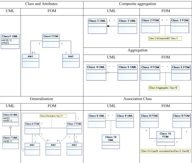
In order to cope with such heterogeneous modelling patterns, we focus our interest on approaches that enable their normalization to a fine-grained semantic model by fragmenting the represented knowledge into atoms. NIAM (Natural-language Information Analysis Method) (Nijssen et al, 1989) proposed to model the world in term of facts (either presenting terms (real things), or representing characteristics (attributes) of these real things), and relationships between facts. NIAM is attribute-free. We adapted this fact-oriented modelling approach idea to the UML (OMG, 2004) class notation representation of the conceptual models. Thus, we developed in (Lezoche et al., 2011) a set of transformation modelling rules, to be applied to selected UML patterns (Table1). In the resulting fact-oriented model, the semantics is preserved by adding annotations. The added annotations concern particular artefacts semantics such as generalisation, association class, aggregation and composite aggregation.
A set of transformation modelling rules, to be applied to selected UML patterns is presented on Table1.
Let us refer to the definitions of LOT and NOLOT facts given in the beginning of section 3. Transforming a particular conceptual model in a fact-oriented model must follow these rules: (1) all classes are transformed into LOT facts. Using UML Class notation, a LOT fact is
represented by a UML Class.
(2) all attributes are transformed into NOLOT facts. Using the UML Class notation, a NOLOT fact is represented as a UML Class.
(3) for each attribute a belonging to a UML Class C, an association is created between the corresponding LOT a and the corresponding NOLOT C, created by the two previous rules.
(4) the multiplicity associated to each attribute a is copied as the multiplicity of the role of the previous association (rule 3) attached to the NOLOT a. The opposite role of the same association must have a constraint multiplicity equal to one.
(5) all “simple” associations between classes are transformed into “simple” associations between NOLOTs.
(6) all generalisation relationships between classes are transformed into “simple” associations with a constraint multiplicity equal to one on the role attached to generalised NOLOT and a non-constraint multiplicity equal to * on the opposite role. In order to trace the fact that this association was derived from a generalisation, we annotate semantically the new corresponding association with a logical predicate. Moreover, the inheritance features of the generalisation association are mapped as new associations between LOTs representing the attributes of the generalised NOLOT, and all the specialised NOLOTs (sub-classes).
(7) composite aggregation and aggregation relationships are transformed into simple association (rule 3) that keep unchanged the existing roles’ multiplicities but trace their specific semantics by an attached semantic annotation.
(8) association classes are transformed into a LOT fact with two associations linked to the corresponding initial LOT facts. The multiplicities of the roles of these two associations are determined by inverting the ones initially formalised on the roles of the previous association.
(9) any other specific constraints (generally modelled using OCL logical rules) are kept during the transformation process.
(10) we did not take into account the special cases of constraints in generalisations because they are not usually used in data conceptual modelling.
One of the conceptual modelling requirements is that a conceptual model must have formal foundations, which allow comparing that model with other conceptual models in a formal and exact way.
Class and Attributes Composite aggregation
UML FOM UML FOM
Aggregation
UML FOM
Generalisation Association Class
UML FOM UML FOM
Table 1 - Fact-Oriented modelling patterns using UML notation
3.4 FOL representation
A concern facing both developers and users of models is the degree of confidence in the model correctness. It is very easy to make errors, including errors in parameter estimations, in model assumptions and in programming. Verification methods are designed to address this question and have become important parts of model building process (Clarke et al., 1996), (Störrle, 2005).
As shown in Table1, a Fact-Oriented Model (FOM) uses semantic annotations to preserve coherence between the input and output models of transformation rules. Since those annotations are not formal objects, we need to verify the real semantics of the FOM model in comparison with the UML one.
(Berardi et al, 2005) and (Tursi et al, 2009) formalised UML class constructs semantics in First Order Logic (FOL) assertions. We propose to adapt and to extend these works to formalise the fact-oriented model patterns (presented in Table 1) in FOL assertions.
3.4.1 Translation of UML Artefacts and Semantic Annotations in FOL
1. UML artefacts
The conceptual models, produced after the first two steps of our approach, are representing concepts semantics using UML artefacts such as class, attribute, association, association class, aggregation, composite aggregation and generalisation. Let us now formalise each of these artefacts in FOL.
Class. A class in UML designates a set of object with common features (OMG, 2004).
Formally a class C corresponds to a FOL unary predicate C.
∀ . (1)
Attribute. An attribute a of type T for a class C associates to each instance of C a set of
instances of AttribType, its multiplicity [i..j] specifies that a associates to each instance of C at least i and at most j instances of AttribType. Formally, an attribute a of type AttribType for
class C corresponds to a binary predicate.
∀ ∀ ∧ , → . (2)
A multiplicity [i..j] is composed of two specifications: the minimal value (i) and the maximal value (j). Those minimal and maximal values are specified as “0” or “1” or “*” or
any positive integer. However, generally, in conceptual models, we do not specify positive integers for multiplicity because those numbers are embedded as constraints into the data processing of the software. We are then restraining our formalisation to the three generic cases: “1” (uniqueness), “0” (absence) and “*” (unlimited). This restraining postulate allows us to model each of the four general multiplicity cases (0..1, 1, 1..*, *) using a logical disjunction operator between the three logical expressions ((3), (4), (5)):
Uniqueness (“1”): for any instance x of class C, there is a unique value for the attribute a in
the instance x.
∀ → ∃ , ∧ ∀ , → . (3)
Absence (“0”): for any instance x of class C, there is not any value for the attribute a in the
instance x.
∀ → ∀ , . (4)
Unlimited (“*”): for any instance x of class C, there is an unlimited number of values for the
attribute a in the instance x.
∀ → ∃ , . (5)
Association. An association in UML is a relation between two or more instances of classes.
The multiplicity [m..n] attached to each role of an association specifies that each instance of the class C can participate at least m times and at most n times to the related association. The
n-ary association construct may always be transformed into two or more binary associations.
Thus an association between two classes and is represented by a unary predicate and two binary predicates and , one for each role name, and can be formalised as the following set of FOL assertions:
∀ ∀ ∧ , → . (6) ∀ ∀ ∧ , → . (7) ∀ → ∃ , . (8) ∀ → ∃ , . (9) ∀ ∀ ∀ ∧ , ∧ , → z . (10) ∀ ∀ ∀ ∧ , ∧ , → z . (11) ∀ ∀ ∀ ∀ ∧ ⋀ , ∧ , → z . (12)
Assertions (6) and (7) are typing the association. Assertions (8), (9), (10) and (11) are specifying that any association has at least one role at each of its ends and that each role is unique; Assertion (12) imposes that each instance of an association is unique.
The multiplicity constraints attached to association roles are formalised with logical expressions having the same structure as the previous ones ((3), (4), (5)) for the attributes.
Association Class. An association may have a related association class that describes
properties of the association, such as attributes, operations, etc. It can be formalised in the same way of an association.
Aggregation. A particular kind of binary associations is aggregation, which plays an
important role in UML class conceptual models. An aggregation is a binary relation between the instances of two classes and , denoting a part-whole relation, i.e., a non-symmetric relation which specifies that each instance of a class (the containing class, ) contains a set of instances of another class (the contained class, ). The aggregation is represented by a unary predicate Aggregation(x) for which all the association assertions are valid. To complete its semantics, in order to formalise the fact that an instance cannot be its own aggregate, the following FOL assertion has to be added:
Moreover, in order to formalise the non-symmetry of the aggregation, the following FOL assertion has to be added:
∀ ∀ ∀ ∀ ∧ ∧ ∧ , ∧
, ∧ ∧ → , ∧ , .
Composite aggregation. Composite aggregation is a strong form of aggregation that
requires a component instance to be included in at most one composite at a time. The composite aggregation is represented by a unary predicate Composition(x) for which all the aggregation assertions are valid. To complete its semantics, in order to formalise the fact that a component cannot participate to more than one composite aggregation, the following FOL assertion has to be added:
∀ ∀ ∀ ∧ , ∧ , ∧ ∧ →
∀ , → .
Moreover, in order to formalise the non-sharing property of the components, the following FOL assertion has to be added:
∀ ∀ ∀ ∀ ∀ ∧ ∧ , ∧ , ∧
, ∧ , ∧ ∧ ∧ → .
Generalisation. In UML, one can use a generalisation between a parent class and a child
class to specify that each instance of the child class is also an instance of the parent class. Hence, the instances of the child class inherit the properties and the relationships of the parent class, but typically they also possess additional properties that do not hold for the parent class. Disjointness and completeness constraints can also be enforced on a class hierarchy. In this paper (and in our conceptualisation approach), we do not take into account
overlapping and incompleteness constraints over a class hierarchy because they generate hidden and poor semantics.
The semantics of a UML class generalizing a class can be formally captured by means of the following FOL assertion:
∀ → .
Disjointness among the child classes … is expressed by the additional FOL assertion:
∀ → Λ , 1, … , .
The completeness constraint, expressing that each instance of the parent class is an instance of at least one of its child classes … , is formally defined by the additional assertion:
∀ → ∨ .
2. Semantic Annotation in Fact-Oriented Model
In order to keep track of the initial model semantics, which may be lost sometimes after applying the FOM transformation rules on specific UML artefacts, we embed semantic annotations of some key modelling constructs (association class, generalisation, aggregation, composite aggregation) in resulting models. These annotations highlight, with the presented logic assertions, the specific semantics that can be lost. For the composite aggregation construct the semantic annotation brings also, in a textual form, the particular semantics of life cycle that relate to its instances.
This section is derived from the following scientific publications:
Lezoche M., Panetto H., Aubry A., (2011). Conceptualisation approach for cooperative information systems interoperability, ACM. 13th International Conference on Enterprise Information Systems, ICEIS 2011, Jun 2011, Beijing, China. pp. 101-110 Lezoche M., Panetto H., Aubry A., (2011). Formal Fact-Oriented model transformations for
cooperative information systems semantic conceptualisation, Selected and extended version of ICEIS 2011. Lecture Notes in Business Information Processing, Proof read
4 A semantics structuring process
After conceptualising and enacting finest-grained semantics embedded into CISs models, resulting with a normalised FOM, the latter has to be structured into semantic aggregates (Yahia et al., 2011). Each of those identified aggregates represents a “semantic molecule”, composed of atomic concepts, with its own minimal mandatory semantics.
To build such aggregates, we propose a recursive approach for analysing the detailed semantics of the IS conceptual models obtained by the conceptualisation approach presented in section 3. We are considering that these models embed the whole explicited semantics of the associated IS.
Our structuring approach starts by identifying core atomic concepts and it ends by computing the semantic aggregates (namely, the semantic blocks) according to algorithms based on graph theory.
4.1 Core and extended semantics
When considering an available fact-oriented conceptual model from one IS (outputs from section 3), we can distinguish the mandatory (constrained) and non-mandatory (non-constrained) association roles, which represent mandatory and non-mandatory concepts expressing semantics.
The set of mandatory concepts represents all the necessary and sufficient elements which make the conceptual model semantically coherent and understandable. It comprises all the non-lexical and lexical concepts linked to constrained association roles with a multiplicity equal to 1 or 1..*. On the contrary, the mandatory concepts correspond to the non-mandatory roles (multiplicity equal to 0..1 or *) and are only enriching the semantics of those IS conceptual models.
To some extent, the set of mandatory concepts corresponds to the core semantics that is embedded into a given IS conceptual model. The extended semantics is defined by the set of mandatory and non-mandatory concepts.
4.2 Some mathematical definitions
We define, for each IS conceptual model, the following notations.
Definition 1. is the set of the identified lexical and non-lexical concepts, formally defined by
| is a lexical or a non lexical concept from the IS conceptual model Moreover, we define two subsets of as follows:
is the subset of restricted to the non-lexical concepts and, is the subset of restricted to the lexical concepts.
We can note that:
∪
∩ ∅
Definition 2. is the set of the identified associations between concepts. Formally, it is defined by
, , ∈ ∧
Definition 3. , is the multiplicity of the role of when considering the association between and if it exists. For each , ∈ , if , exists then we have , ∈ ∗ ,0. .1,1,1. .∗ and it is read is associated to with a multiplicity equal to , .
Definition 4. is the subset of restricted to mandatory concepts (the core semantics). It is formally defined by
∃ , , ∈ ∧ , ∈ 1,1. .∗
Moreover, we define two subsets of as follows:
is the subset of restricted to the mandatory non-lexical concepts and, is the subset of restricted to the mandatory lexical concepts.
We can note that:
∪
∩ ∅
∩ ∩
Definition 5. For each non-lexical concept , we can define the set of its associated
mandatory lexical concepts as follows:
∈ ∃ , ∈ , ∈ 1,1. .∗
Definition 6. For each non-lexical concept , we can define the set of its associated
mandatory non-lexical concepts as follows:
∈ ∃ , ∈ , ∈ 1,1. .∗
If we consider a concept defined in the context of the IS core semantics, we notice that, in order to be semantically effective in the studied domain, this concept needs to be associated
on the one hand to its mandatory lexical concepts and on the other hand to other non-lexical concepts. This defines the notion of Semantic Block (SB).
4.3 Semantic blocks identification
1. Definition
Considering a particular non-lexical concept from , a semantic block, denoted as and associated with the concept , represents the set of the concepts necessary for the minimal semantics definition of the non-lexical concept given by the conceptual model. Formally, B is defined as follows:
∪
∈
1
This definition, suggests that the notion of semantic block is recursive.
In the following, the meta-model of the semantic block is given and a procedure to compute all the semantic blocks of a conceptual model is proposed.
2. Semantic block meta-model
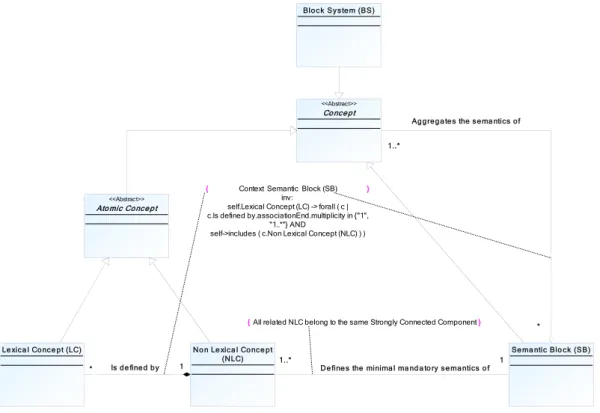
Here we propose to formalise the semantic block architecture through the meta-model represented on Figure 3. This meta-model is based on the composite pattern (Gamma et al, 1995). This meta-model defines an arborescence of components representing hierarchies of objects.
Figure 3 - Meta-model of the semantic block structure
A semantic block defines the minimal mandatory semantics of one or several non-lexical concepts such that these concepts are in the same strongly connected component1. Moreover, the semantics of one or several concepts can be aggregated into one or several semantic blocks. As the semantic block is a specialisation of the abstract class “Concept”, its semantics can be aggregated into one or several semantic blocks of higher levels. The Block System represents the last level of aggregation and contains the minimal mandatory semantics of the studied IS conceptual model.
3. How to build the Semantic blocks?
Let us consider the conceptual model on Figure 4 and its transformation on Figure 5 obtained by applying the third step presented in section 3. Let us build the semantic block of the concept 2. The intrinsic mandatory semantics of the concept 2 is defined by the
1 A strongly connected component of a directed graph is a maximal set of vertices such that for every pair of
vertices u and v, there is a directed path from u to v and a directed path from v to u. No n Le xica l Co nce pt (NLC) Le xica l Co nce pt (LC) 1 Is de fine d by *
Ato mic Concep t
<<Abstract>>
Se ma ntic Blo ck (SB) 1
De fine s the minima l ma nd a to ry se ma ntics o f 1..*
} {All related NLC belong to the same Strongly Connected Component
Co nce pt
<<Abstract>>
Blo ck System (BS)
1..*
Aggrega tes the sema ntics of
*
} { Context Semantic Block (SB)
inv:
self.Lexical Concept (LC) -> forall ( c | c.Is defined by.associationEnd.multiplicity in {"1",
"1..*"} AND
semantics of the mandatory lexical concepts that are associated to it, namely 1 2 and 2 2. Moreover, a given instance of the concept 2 exists only if it is associated to at least one instance of the concept 5 . That means that 5 is mandatory for expressing the semantics of 2. Moreover, considering the roles of 1 and 3 in their association with 2, we can see that the minimal multiplicity is equal to 0. That means that the existence of any instance of 2 is not stipulated by the existence of one instance of 1 or 3. Finally, we find again 2 2 ∪ 1 2, 2 2 ∪ 5 as in equation (1).
Recursively, we can demonstrate that the intrinsic mandatory semantics of the concept 5 is defined by the semantics 1 5 and that a given instance of the concept 5 exists only if it is associated to exactly one instance of the concept 8 and exactly one instance of the concept
2. That means that 5 5 ∪ 1 5 ∪ 2 ∪ 8 .
Applying the same reasoning, we can build 8 as follows: 8 8 ∪ 1 8 .
Finally we can deduce that: 2 2, 5, 8 ∪ 1 2, 2 2 ∪ 1 5 ∪
1 8 .
Figure 4 - An instance of conceptual model
C1 +A1C1[1] +A2C1[0..1] C2 +A1C2[1] +A2C2[1] +A3C2[0..1] C3 +A1C3[1] +A2C3[0..1] C4 +A1C4[1] +A2C4[0..1] 1..* * 1 * 1..* 0..1 C5 +A1C5[1] +A2C5[0..1] 1..* 0..1 1 * C8 +A1C8[1] +A2C8[0..1] 1 * C6 +A1C6[1] +A2C6[0..1] 1..* 1..* C7 +A1C7[1] +A2C7[0..1] 1 1 1..* * 1 0..1 * 0..1 * * 1 1..* 0..1 0..1 * 0..1
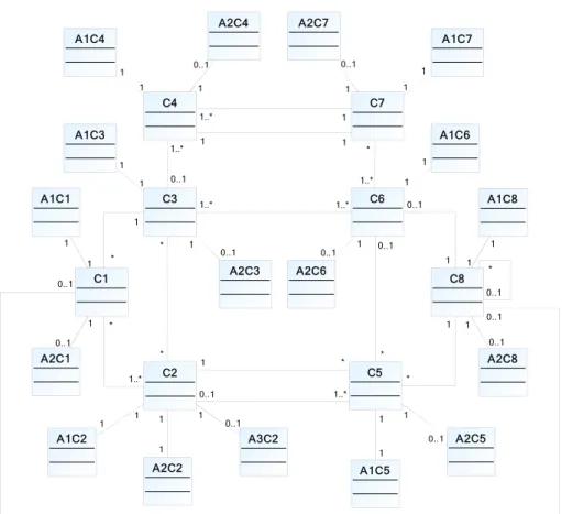
Figure 5 - "Fact-oriented modelling" transformation of the model of Figure 4
To simplify the computation of the semantic block of one concept , we propose, first, to identify the set of non-lexical concepts that are included in the semantic block and, second, to add the associated mandatory lexical concepts. That means that is determined as
follows: ∪ with
⋃ ∈ and,
∈
For instance, 2 2, 5, 8 and 2 1 2, 2 2, 1 5, 1 8 .
C1 C2 1..* * C3 * * 1 * C4 1..* 0..1 C5 1 * 1..* 0..1 C6 * 0..1 1..* 1..* C7 1 1..* 1..* * 1 1 C8 0..1 * 0..1 0..1 1 0..1 1 * A1C1 1 1 A2C1 1 0..1 A1C2 1 1 A2C2 1 1 A3C2 0..1 1 A1C5 1 1 A2C5 0..1 1 A1C8 1 1 A2C8 0..1 1 A1C6 1 1 A2C6 0..1 1 A1C3 1 1 A2C3 0..1 1 A1C4 1 1 A2C4 0..1 1 A2C7 1 0..1 A1C7 1 1
4.4 Using graph theory for building
To facilitate the building of the semantic blocks, we propose, for each from C , to identify the associated set by using graph theory modelling and its associated mathematical tools.
Let us first define a semantic-dependency graph associated with a conceptual model. This semantic-dependency graph is a digraph , where is the set of nodes and is the set of edges defined by a pair of nodes. Each node from represents a non-lexical concept of the conceptual model. Each edge from is built from the conceptual model as follows: the edge , exists if (i) there is an association between and in the conceptual model, and (ii) if the minimal multiplicity for the role of is equal to 1 ∈ . That means that the existence of the edge , represents the fact that is mandatory for expressing the semantics of .
The Figure 6 shows the semantic-dependency graph associated with the conceptual model of the Figure 5.
Figure 6 - Semantic-dependency graph associated with the conceptual model of Figure 5
Theorem 1. Given two particular concepts c and c , c belongs to SB c if and only if there exists a directed path from c to c .
1 2 3 5 8 4 7 6
Proof. Let us consider the conceptual model on Figure 4. To build the semantic block of the
concept c , we consider this concept as the starting point. This concept can thus be considered as the root in the associated semantic-dependency graph. Now we add in SB c all the concepts c that must be instantiated to ensure the existence of a particular instance of c , i.e. all the concepts c such that there is an association between c and c in the conceptual model, and the minimal multiplicity for c , considering this association, is equal to 1. This is the exact definition of all the successors of c in the semantic-dependency graph. Note that, by definition, there is a directed path from the concept c to these concepts c . Iteratively, the only new concepts c that can be added to SB c are the successors of those first concepts c . As successors of the concepts c , there exists also a directed path from the concept c to the concepts c (the path from c to c plus the edge c , c ). Finally the semantic block of c contains exactly all the concepts c such that there exists a directed path from c to c . ∎
Theorem 2. Given two particular concepts c and c , if c belongs to SB c then SB c is included in SB c .
Proof. c belongs to SB c means that there exists a path from c to c (see theorem 1). Let us now consider a particular concept from SB c denoted as c. By definition of SB c , there exists a path from c to c and then a path from c to c (the path from c to c plus the path from c to c). That means that c is in SB c . Finally SB c ⊆ SB c . ∎
Theorem 3. All the concepts that are in the same cycle in the semantic-dependency graph
are associated with the same unique semantic block.
Proof. A cycle is a closed path. Let us consider two particular concepts, denoted as c and c , which belong to a cycle. In particular there is a path from c to c . That means that c is in SB c . Following the theorem 2, we can also demonstrate that SB c ⊆ SB c . Moreover, there is a path from c to c . That means that c is in SB c . Following the theorem 2, that means that SB c ⊇ SB c . Finally, SB c SB c . ∎
The theorem 3 implies that there is one semantic block per strongly connected component of the semantic-dependency graph.
4.5 A procedure to compute the semantic blocks
Applying theorems 1 to 3, we propose the following procedure to compute all the semantic blocks of a given conceptual model:
i. Building the associated semantic-dependency graph.
ii. Building the graph of the strongly connected components based on the semantic-dependency graph.
iii. Computing the semantic blocks associated with each strongly connected component.
iv. Computing, for each , the semantic block by adding all the mandatory lexical concepts associated to each non-lexical concept from .
v. Computing ∪ .
These steps are detailed as follows.
4.5.1 Building the associated semantic-dependency graph
By definition of this graph, it can be easily obtained by considering each association between two concepts c and c and then building an edge from c to c if the minimal multiplicity for the role of c is equal to 1.
4.5.2 Building the graph of the strongly connected components
Theorem 3 implies that for building the semantic blocks, we can consider only one concept in a given strongly connected component (the other concepts share the same semantic block). That is the reason why we can simplify the semantic-dependency graph by considering only an equivalent graph where the nodes represent each strongly connected component of the former semantic-dependency graph, and where one of these nodes (e.g. SCC1) is connected
to another node (e.g. SCC2) if there exists at least one edge from a concept from SCC1 to a concept from SCC2.
Identifying all the strongly connected components of a graph is a well-known problem in graph theory that can be solved with polynomial effort by using Kosaraju-Sharir’s algorithm (Sharir, 1981).
The graph of the strongly connected components related to the semantic-dependency graph of Figure 6 is given on Figure 7. On this graph, the strongly connected components are defined as follows SCC1 C1 , SCC2 C2, C5 , SCC3 C3, C4, C6, C7 and SCC4
C8 .
Figure 7 - Graph of the strongly connected components related to the graph of Figure 6
4.5.3 Computing associated with each strongly connected component
We propose now one algorithm for computing all the semantic blocks SB associated with each strongly connected component (see Algorithm 1 that invokes Algorithm 2). The algorithm 1 BuildSemBlocks is applied on the graph of the strongly connected components (denoted as G ).
Let us apply the algorithm BuildSemBlocks G on the graph of Figure 7. We obtain the following semantic blocks:
1 1 ∪ 2 ∪ 3 ∪ 4, 2 2 ∪ 4, 3 3 ∪ 4 and 1 2 3 4
4 4.
And finally replacing the strongly connected components by their content we obtain the following semantic blocks:
1 1, 2, 3, 4, 5, 6, 7, 8 , 2, 5 2, 5, 8 , 3, 4, 6, 7 3, 4, 6, 7, 8 and 8 8 . Algorithm [Initialisation]
: List of the strongly connected components in
For each ∈ Do
1
[ is an indicator that defines if a node has already been visited or not]
[-1 means not yet visited] [0 means being visited] [+1 means already visited]
Next
For each ∈ Do
If 1 Then
[Building of the semantic block associated with ]
[calling Algorithm 2]
EndIf Next Return
Algorithm 1. BuildSemBlocks algorithm
Algorithm
[Initialisation]
[The semantic block associated with
SCC initially contains all the concepts in the SCC]
0 [SCC is being visited]
[Building] [use of theorem 1]
For each ’ successor from in Do
If ’ 1 Then
[Building of the semantic block associated with
’]
’ EndIf
[Use of theorem 2]
∪ ’
Next ’ successor from in Return
Algorithm 2. BuildSB algorithm
4.5.4 Computing, for each , the semantic block
Each semantic block contains the mandatory lexical concepts associated to the
non-lexical concepts in . By applying the definition of ∈
on the instance of Figure 5 we obtain:
C1 1 1, 1 2, 2 2, 1 3, 1 4, 1 5, 1 6, 1 7, 1C8 , C2, C5 1 2, 2 2, 1 5, 1C8 ,
C3, C4, C6, C7 1 3, 1 4, 1 6, 1 7, 1C8 and
4.5.5 Computing each semantic block
Each semantic block is the union of and . By applying this definition on the instance of Figure 5 we obtain:
1
1, 2, 3, 4, 5, 6, 7, 8 ∪ 1 1, 1 2, 2 2, 1 3, 1 4, 1 5, 1 6, 1 7, 1 8 , C2, C5 2, 5, 8 ∪ 1 2, 2 2, 1 5, 1C8 ,
C3, C4, C6, C7 3, 4, 6, 7, 8 ∪ 1 3, 1 4, 1 6, 1 7, 1C8 and
C8 8 ∪ 1C8 .
For validating our approach, next section will detail an industrial case study involving two enterprise information systems that need to interoperate: Sage X3 ERP and Flexnet MES.
This section is derived from the following scientific publication:
Yahia E., Lezoche M., Aubry A., Panetto H., (2011). Semantics enactment in Enterprise Information Systems, IFAC. 18th IFAC World Congress, IFAC WC'2011, Aug 2011, Milan, Italy. Elsevier - IFACPapersOnline, 18, 13064-13073
5 Case Study
Interoperability between organisational and manufacturing activities is crucial in manufacturing enterprises. Production services have to produce, quickly and efficiently, the right volume of the right product at the right moment. For this reason, they need real time information coming from others services, which need in return a precise and updated data on production. We propose here to study and present the first part of such a B2M interoperability issue by considering Sage X3 as an Enterprise Resource Planning (ERP) application and Flexnet as a Manufacturing Execution System (MES). Such interoperation process is based on a deep semantics analysis of their own models. In order to illustrate our approach, we will detail the conceptualisation process applied to a subset of the ERP information system model in section 5.1. Section 5.2 will detail the semantics structuration process (computing semantic blocks) applied to a subset of the MES information system model. For sake of readability, in the following, we will name each subset of models by the name of the related enterprise applications.
5.1 Conceptualisation of Sage X3 ERP model
An Enterprise Resource Planning (ERP) system is an integrated computer-based system which is used to manage internal and external resources including tangible assets, financial resources, materials, and human resources (Bidgol, 1997). Its purpose is to facilitate the flow of information between all business functions inside the boundaries of the organization, as well as to manage the connections to outside stakeholders. Built on a centralised database, ERP systems integrate all business operations into a uniform system environment. Sage X3 provides different enterprise management functions: finance, commercial, industrial and services.
The objectives of this case study are (i) to analyse how the manufacturing order process inside the Sage X3 application is modelled, (ii) to use the proposed modelling process for making the implicit knowledge explicit in the model structure.
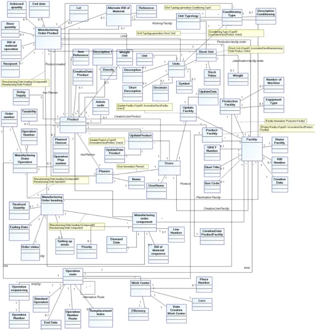
The model depicted on Figure 8 is the output from the first two steps of our approach. This means that we have already completed the “Reverse Engineering” and the “Expert knowledge injection” steps. The “Manufacturing Order Heading” concept represents the management function of production orders and planned activities. This function allows the generation of a manufacturing order by variation of one or more classifications and a single production line. For each manufacturing order, the achievement of the material benefits and sequencing operations is possible. The function captures general information, such as planning and production facility and the status of the order. It allows entering general information about the production order. The availability of components is then checked through the information given by the bill of material related to the launched products. Once the above initial information is determined, the system updates the list of materials and operations of the created or modified orders.
Step 1: Reverse Engineering
All this information is stored in the Sage X3 application database. The first step of our method is to reverse-engineer the database, in order to extract the initial conceptual model by using standard tools in MEGA Suite. In this particular case, the resulting model is composed only of a set of classes and attributes without any associations. This is due to the fact that all relationships between concepts are directly implemented into the application software instead of in the database. We can note also that the implementation names of the entities (coming from tables and columns) are quite raw and not expressive. The bottom of Figure 9 shows two classes extracted from the reverse-engineered conceptual model. The objective of the next step is then to clean and enrich this model.
Figure 8 - Enriched Sage X3 manufacturing order process model Step 2: Expert Knowledge Injection
The model depicted in Figure 8 is the result of the reverse engineering step and is enriched by a domain expert. In this case, the enrichment process involved a significant human effort
because the architecture of the Sage X3 ERP is built with all the database relationships implemented directly into the application layer and not in the database. The reverse engineering step results, as shown in the lower part of the Figure 9, in a model containing classes with coded names and no associations.
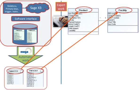
Figure 9 - Sage X3 architecture and expert knowledge injection
The expert work is about cleaning this conceptual model according to the best practices in the enterprise, modifying the attributes multiplicity (if needed), renaming the concepts, the attributes and the associations to fit the conceptual model to the “real” use of the Enterprise Information System. The typical case that requires the domain expert attention is the mandatory properties in forms’ fields.
Let us consider the same example as in section 3.2. In the studied enterprise, a good practice is imposed for achieving information update traceability. When a user updates information concerning one product, the application must store, in dedicated fields, the date of the update and the name of the logged user. This feature is implemented directly into Sage X3 ERP but it is not reflected in the data model. Moreover, for the sake of simplifying the
implementation, the developers did not set these attributes as mandatory. In order to consider this practice in the conceptual model, the expert can conceptualise this constraint as one mandatory association between the existing concepts Product and Users and by constraining the existing attribute UpdateDate in the association class related to the previous association (as on Figure 9).
Step 3: Fact-Oriented Transformation
Applying the pattern transformation rules, presented in the previous section, classes and attributes are transformed into NOLOTs and LOTs respectively to increase the granularity of the knowledge embedded into the model. These rules have been coded by using a Mega Suite internal version of VBA scripting language and then automatically executed inside MEGA Suite.
Figure 10 shows the resulting FOM after applying our approach to the Sage X3 work order process.
At the first glance, it seems that the resulting model is much more complex than the initial one. This may looks true from a visual point of view, but it is false in terms of expressiveness of the model’s semantics. Indeed, the finest-grained atoms of semantics are now made explicit, which helps any automatic computing. An important result is that using the model with such high level of granularity will facilitate automatic execution for semantic gap evaluation.
Figure 10 - Sage X3 manufacturing order process model - fact-oriented version
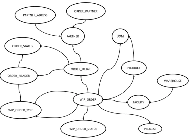
5.2 Semantics structuring of Flexnet MES model
Manufacturing Execution Systems (MES) are information technology systems that manage manufacturing operations in factories. Actually, a specific process implemented in Flexnet application has been chosen to support our validation process; it consists of the purchase order process. Figure 11 represents the enriched fact-oriented model of this process. Note that, in this model, classes with capital letters represent the non-lexical concepts. In order to