CON250-1
CSCE Annual Conference
Growing with youth – Croître avec les jeunes
Laval (Greater Montreal)
June 12 - 15, 2019 / 12 – 15 Juin, 2019
SUBSTRUCTURING STRATEGY FOR PSEUDO-DYNAMIC TESTING OF
STEEL LATTICE TOWERS.
Kammouh, R.
1, Sad Saoud, K.
1, Lamarche, C.-P.
1, Langlois, S.
1, 2, Loignon, A.
11 Université de Sherbrooke, Canada
Abstract: Lattice towers are the most commonly used structures in the field of overhead power transmission lines. In the design process of transmission lines, there are several methods for the evaluation of their capacity. The most common design method involves the use of three-dimensional linear elastic truss analyses to evaluate the axial forces in the pin-ended members. The resulting design is normally validated by full-scale experimental tests. These tests are very expensive and time-consuming. Moreover, the rarity of the testing facilities represents an additional difficulty. Hence there is an interest of using substructured pseudo-dynamic testing methods in which the experimental substructure, tested in a laboratory environment, interacts with a numerical model to emulate the structural behaviour of a complete structure. This method has several advantages but requires several preliminary analyses and planning for defining the critical substructure, dynamic parameters, and the setup’s flexibility. This work aims to develop a completely numerical substructuring strategy using the finite element software Code_Aster to ensure relevance and simplify the preparation and planning of pseudo-dynamic tests on lattice towers. An example of a lattice tower, under quasi-static load case is presented and compared with reference numerical analyses’ results. The effect of dynamic parameters (time step, damping ratio and load rate) on the emulated structure’s behaviour is analyzed in detail. Finally, the effects due to the flexibility of a simplified test set-up on the accuracy of the test results is studied.
1 INTRODUCTION
In the field of overhead power transmission lines, a simplified numerical model based on the finite element method is generally used to determine the members’ axial forces. Then, the standard design equations are used to evaluate the members’ axial load carrying capacities. The resulting design is normally validated by full-scale experimental tests. These tests are very expensive and time consuming. Moreover, the rarity of the testing facilities represents an additional difficulty. Hence, it becomes interesting to use substructured pseudo-dynamic testing methods, in which an experimental substructure, which exhibits a highly complex behaviour, tested in a laboratory environment, interacts with a numerical model to emulate the structural behaviour of a complete structure. The substructured pseudo-dynamic test method was first proposed by the Dermitzakis and Mahin (1985). Recently, this testing method was largely used to evaluate the performance of building structures and bridges under dynamic loading, but not much in the case of steel lattice tower structures. The substructured pseudo-dynamic testing method was used at Université de Sherbrooke to evaluate the strength of a reduced-scale lattice tower [Loignon et al. (2016)], where it was demonstrated that the substructured pseudo-dynamic test on a reduced scale lattice tower (scale 1:4), under quasi-static loading, allows to accurately reproduce the performance of the entire structure. In the study of Loignon et al. (2016) several preliminary analyses for defining the critical substructure, selecting
CON250-2
the proper dynamic parameters to use, and evaluate the impacts of the test set-up’s flexibility on the results were performed in order to plan and perform the final test.
In this paper, a completely numerical substructuring strategy using the finite element software Code_Aster has been developed to ensure relevance and simplify the preparation and planning of pseudo-dynamic tests on a full-scale steel lattice towers. The developed strategy employs beam elements to represent the angle members and discrete elements for the bolted connections. Both the eccentricity and the rotational stiffness of the connections are modeled. The highly nonlinear behaviour of the critical substructure is modeled by performing an incremental static finite element analysis considering both geometric and material nonlinearities. The proposed strategy investigates the effect of the dynamic parameters (time step, damping ratio and loading rate) on the accuracy of the results of an emulated structure’s behaviour. An example of a lattice tower under quasi-static loading is presented and compared with reference numerical results.The effect of the flexibility of a full-scale experimental test set-up on the accuracy of the test results is studied as well.
2 NUMERICAL MODELING APPROACH
The open-source software Code_Aster [Code_Aster, (2017)] based on the finite element method is used to model the lattice tower. The hypotheses used for the modeling process are those proposed by Bouchard (2013)and are presented below.
2.1 Angle members
The angle members are modeled using beam elements based on Timoshenko beam theory, where the transverse shear effect is considered. Angle members are prone to fail by flexural-torsional buckling including warping phenomena. To consider the warping effect, the beam element POU_D_TG was developed in Code_Aster. The beam element POU_D_TG is composed of two nodes which comprise seven degrees of freedom (dof) each: three for translations, three for rotations and one for warping. Beam elements POU_D_TG will be used to realize a linear dynamic analysis on the global substructure. Furthermore, in Code_Aster, the multifiber beam element POU_D_TGM, which integrates large displacements and large rotations and an elastoplastic material model based on the von Mises yield criterion is available. The multifiber beam element POU_D_TGM will be used in the numerical substructuring strategy to consider the geometric and material highly nonlinear behaviour of the critical substructure.
2.2 Eccentricities
The angles are generally connected in the middle of one leg, which creates an eccentricity between the centroid of the cross-section and the connection point. Because of these eccentricities, secondary moments arise. Several approaches have been proposed to consider the effect of eccentricities. Rao and Kalyanaraman (2001) considers the eccentricity by connecting the centroid of the section with the bolt connection point using rigid elements. Based on Rao and Kalyanaraman (2001) work, Bouchard (2013) models in Code_Aster the eccentricity using rigid links that connect the point of connection and the centroid of each angle.
2.3 Connection stiffness
In a lattice tower, the stiffness of the connections can vary from one connection to another (rigid, semi-rigid or pinned connections). When two angles are connected by a single bolt, the connection is generally considered as pinned. In the case of a connection with more than one bolt, the connection is generally considered as rigid or semi-rigid. According to Lee and McClure (2007), modeling steel lattice tower with rigid connections, overestimates the ultimate capacity of the structure. Lee and McClure (2007) consider that connections with a single bolt should be modeled as perfectly pinned. In this work, to represent the semi-rigid connections, bolted connections are modeled using discrete elements which may have variable
CON250-3
rotational stiffness. The values used for the rotational stiffness are those calculated numerically by Bouchard (2013) based on some typical connection configurations.
3 SUBSTRUCTURING STRATEGY
In this paper, the numerical substructuring strategy is based on the so-called “global” substructuring method described by Lebon (2011). This substructuring strategy consists of modeling separately the critical part (typically with a highly nonlinear behaviour) of a structure, designated as the local substructure (LS), considering both geometric and material nonlinearities. The rest of the structure (generally with a linear behaviour) is designated as the global substructure (GS). Using this method, in the global substructure, the entire structure is numerically modelled, considering all the degrees of freedom (without dof condensation), including those of the critical substructure but neglecting their stiffness. The interaction between the global and the local substructure is done by means of a script, allowing the transfer of displacements and restoring forces vectors at each time step.
At each time step, the displacement vector calculated numerically in the global substructure, is applied to the local substructure at the interface between the global and local substructure through control nodes. The critical substructure fixed at its base reacts due to the applied displacement vector and generates restoring forces, which are sent back to the global substructure at the same interface. The equation of motion, in the global substructure, is solved using the Rosenbrock-W semi-implicit scheme, developed by Lamarche et al. (2009), which is second-order accurate and unconditionally stable. In the course of this project, the Rosenbrock-W scheme was implemented in the Code_Aster environment. Other integration schemes readily available in Code_Aster are implicit in nature and generally require an iterative procedure to converge to a solution, which increase the calculation time. Other explicit schemes such as the central difference method are also available but are conditionally stable.
Once the modeling of the substructures is done, the next step is to define the dynamic parameters (time step Δt, loading rate P0/td and damping ratio ξ), which are inputs for the dynamic analysis. The structured
test is preformed according to the following steps, as illustrated in Figure 1: While (instability or calculation ends)
1. increment the external load vector fi;
2. solve the equation of motion using the Rosenbrock-W integration scheme in the global substructure; 3. apply the displacement and rotation vector xi+1 at the control node on the local substructure;
4. solve the nonlinear static problem in the local substructure; 5. calculate the corresponding restoring force vector rei+1;
6. send back the restoring forces vector rei+1 to the global substructure;
CON250-4
Figure 1: Schematic of the numerical substructuring strategy
3.1 Definition of dynamic parameters
In this section, the dynamic parameters required for the substructuring method will be defined for the quasi-static load case. Generally, for pseudo-dynamic tests with substructuring, the inertial and damping effects in the local substructure are negligible due to the slow loading rate and the low mass of the structure. Ideally, for this kind of test, dynamic parameters are chosen so that the total duration of test is reasonably short and the accuracy is satisfactory.
3.1.1. Time step Δt
The influence of the time step size on the accuracy of the Rosenbrock-W scheme was studied by Lamarche et al. (2009). The precision of the numerical integration scheme is investigated by evaluating the artificial lengthening of the fundamental period and the artificial damping ratio of a single degree of freedom system. Knowing the fundamental period of the structure, a sufficiently small-time step can be chosen that minimises the numerical errors to a satisfactory level.
3.1.2. Loading rate (P0/td)
To reproduce a quasi-static load case, the load is applied slowly using a linear ramping function. Because a dynamic model is used to represent a quasi-static problem, dynamic effects can arise if the load is applied rapidly and/or if the dynamic properties of the model are not chosen appropriately (mass, damping). In order to find an appropriate load rate to minimise the dynamic effects in a structural model, Béga (2017) theoretically calculated the maximum absolute displacement error between the dynamic response and the static response of an undamped one degree of freedom system loaded with a linear ramping force (see Equation 1). ea= P0 2πk( T td) [1]
CON250-5
Figure 2 : Absolute error ea between the static and dynamic responses of a one degree of freedom
system [Béga (2017)]
where ea is the displacement error caused by the dynamic effects relative to the static response of the
system. The absolute error ea is depicted graphically in Figure 2, where the displacement u(t) is presented
as a function of time for both dynamic and static responses of a one degree of freedom system with stiffness
k subjected to a linear ramp load of P0 maximum intensity and a loading time td. The relative error er is
calculated by dividing ea by the final theoretical static displacement us(td) = P0/k. For a monotonic loading
pattern, the relative error decreases as loading time td is increased. In this work, the effect of the loading
rate will be studied in the context of the proposed dynamic substructuring strategy in order to minimize the relative error er and find a proper loading rate allowing to reproduce a quasi-static load pattern.
3.1.3. Damping ratio ξ
The effect of the damping ratio for the lattice tower example considered in this paper is analyzed using the developed numerical substructuring strategy. Several numerical substructured simulations of a lattice tower considering several damping ratios are realized in order to select an adequate damping ratio that allows to reduce the dynamic effects without affecting the global behaviour of the structure.
4 APPLICATION EXAMPLE
This section presents an example of application of the numerical substructuring strategy on a full-scale lattice tower under quasi-static loading. The results of the numerical substructuring strategy are compared to a nonlinear pushover analysis of the entire structure. The effect of the flexibility of a simple test set-up on the accuracy of the test results is also investigated.
4.1 Analyzed structure
The lattice tower that is investigated is presented in Figure 3. This structure measuring 39.95 m in height is analysed using the numerical substructuring strategy and the results are compared to the results of a nonlinear pushover analysis. In both models, the steel material is modeled using a bilinear elastoplastic stress-strain curve where the yield strength is Fy = 380 MPa, Young’s modulus is E = 200000 MPa and the
strain hardening modulus is equal to E/100, as proposed in EN 1993-1-5 [EC3, (2004)].
Prior to the analyses, a mesh convergence study was carried out by performing nonlinear second-order analyses of a fixed-pinned angle member under compression to determine an appropriate number of finite beam elements to use per angle member. This convergence analysis showed that fifteen elements per member is sufficient to model the nonlinear behaviour of the angle under compressive loads. The lattice tower presented in Figure 3 is fixed at its base.
CON250-6
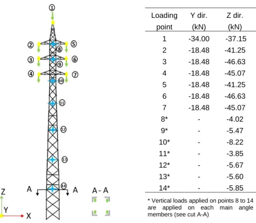
Loading Y dir. Z dir. point (kN) (kN) 1 -34.00 -37.15 2 -18.48 -41.25 3 -18.48 -46.63 4 -18.48 -45.07 5 -18.48 -41.25 6 -18.48 -46.63 7 -18.48 -45.07 8* - -4.02 9* - -5.47 10* - -8.22 11* - -3.85 12* - -5.67 13* - -5.60 14* - -5.85 * Vertical loads applied on points 8 to 14 are applied on each main angle members (see cut A-A)
Figure 3 :Lattice tower: loading points and load values
The load case applied on the analyzed structure comprises the self-weight of the structure, vertical and horizontal loads. The loads are applied to the structure at the loading points shown in Figure 3. The calculation of the load case is based on a design calculation for 45 mm of ice without wind.
Based on a modal analysis of the lattice tower presented is Section 4.1, the fundamental natural period of vibration is T = 0.49 s.
4.2 Pushover analysis of the lattice tower
A pushover analysis of the entire structure was performed to identify the critical substructure to be investigated, i.e., the substructure where the failure mechanism of the tower appears. The lattice tower was modelled according to the methodology presented in Section 2. A study by Sad Saoud et al. (2018) demonstrated that connection eccentricities in lattice tower have a greater influence than initial member imperfections (out-of-straightness) on the ultimate capacity of these structures. Therefore, no initial imperfections were taken into account in the present model. The highly nonlinear pushover analysis was solved incrementally. At the beginning of the analysis, the load is incrementally applied in force control until an instability is encountered. Afterward, to continue the analysis, the arc-length method is used.
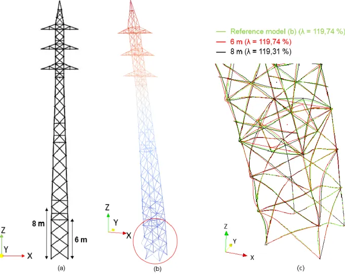
The post-buckling deformed shape obtained from the pushover analysis is presented in Figure 4 (b). The pushover analysis revealed an instability that occurred at a critical load of about λ =120 % of the load pattern presented in Figure 3. The normalised parameter λ correspond to the maximum total load level reached during the analysis divided by the sum of the loads presented in Figure 3.
CON250-7
During a hybrid simulation, the displacements and rotation obtained from the numerical integration scheme are applied to the substructure by a control node located in the center of a rigid control surface (rigid in-pane and out-of-plane). In our case, the control node is located at the center of gravity of the cross section of the tower in the X-Y plane. To make sure that the rigid surface hypothesis does not influence the collapse mechanism of the tower, two extra pushover analyses were performed. One including a rigid surface located at 6 m from the base, and another including a rigid surface located at 8 m from the base. The deformed shapes obtained from these analyses and the corresponding normalised load level reached are presented in Figure 4 (c). The results of these two pushover analyses, are very similar in terms of load levels and failure modes. The relative error between the two models in terms of critical load is very low. This suggests that the 6 m high substructure could be used efficiently in the numerical substructuring procedure.
Figure 4 : Results of the pushover analyses: (a) potential substructures; (b) deformed shape after the collapse; (c) effect of the rigid control surface
4.3 Validation of the substructuring method
The substructure to be “tested” corresponds to the 6 m high bottom portion of the tower where the collapse occurred during the pushover analysis. Two parametric studies using the substructuring procedure were carried out to evaluate the effects of the loading rate and the damping ratio on the behaviour of the emulated structure. In both studies, the load case applied on the global substructure was the same as the one
CON250-8
presented in Section 4.1. The time step chosen for the two parametric studies is Δt = 0.02 s, which
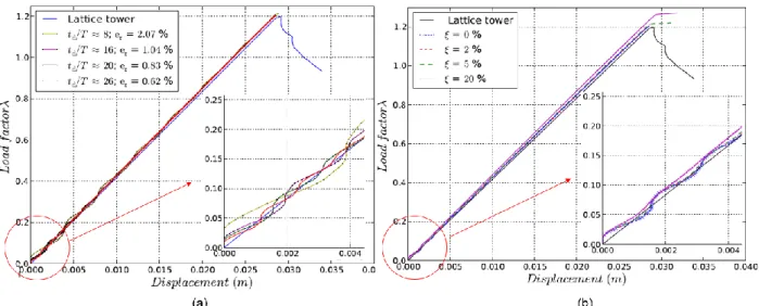
correspond to a time-step over fundamental period ratio Δt/T = 0.041. The testing procedure presented in Section 3 was used to perform the simulations. The results obtained from the two parametric studies are compared to the reference nonlinear pushover analysis’ results in Figure 5, where the normalized load factor λ as a function of the displacement in the Y direction at the control node is plotted for several simulations. In the case of the pushover analysis, the post-peak behaviour of the tower could be obtained. In the case of the substructured simulations, the responses are plotted up to the point where the emulated tower became unstable and convergence could no longer be reached by the integration algorithm. In Figure 5 (a), four substructured undamped simulations using different ratios td /T are presented and compared with
the response from the pushover analysis. At the beginning of the substructured simulations, spurious oscillations caused by the dynamic nature of the models are clearly observable. The relative amplitude of these small oscillations with respect to the applied force becomes less important as the load level is increased. This is confirmed by the maximum relative error being equal to 2.07 % at the end of the simulation for the worst-case scenario (td /T = 8). As expected, when the loading time td is decreased, the
dynamic effects are more important. In Figure 5 (b), three substructured damped simulations using damping ratios ranging from 2 to 20 % of critical damping with td/T = 20 are presented.Rayleigh damping based on
the first and second modes of vibration was used.As already observed in the undamped simulation, there are spurious oscillations at the beginning of the substructured simulations. In the damped case, however, these oscillations are damped quite quickly as the simulations progress. When the value of the damping ratio used is higher than 20% of critical damping, the stability of the tower is artificially maintained beyond the failure mechanism by viscous stabilizing forces as the structure accelerates considerably when the tower becomes structurally unstable. It should also be mentioned that the load displacement curves in the damped case are slightly shifted upwards due to the additional damping forces generated by the fact that the tower is moved by external loads at a steady rate in the linear regime prior to the collapse.
Figure 5 : Parametric studies: (a) effect of the loading rate; (b) effect of damping ratio 4.4 Flexibility of the test set-up
Applying the correct target displacements and rotation at control node in the laboratory is a key factor of a successful hybrid test. The flexibility of the test set-up typically leads to smaller applied displacements and rotations. From an algorithmic point of view, this is the equivalent of introducing spurious energy into the system. These systematic errors are usually associated with a resonance-like phenomena which may result in significant error propagation effects [Dermitzakis & Mahin, (1985)]. The test set-up considered herein is essentially a transfer beam that is attached to the four main angle members part of the critical substructure
CON250-9
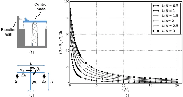
to be tested. The two displacement components and the rotation at the control node are applied using servo-hydraulic actuators that are attached on one end to the transfer beam and on the other end to a reaction wall, or a test floor, as presented in Figure 7 (a). An idealized structural model of the set-up is depicted graphically in Figure 7 (b), where the vertical displacement is applied controlling Δ1 and Δ2,
considering Δ1 =Δ2. The horizontal displacement is applied controlling Δ3, and the rotation c is applied
controlling Δ1 and Δ2 considering c =(Δ2 -Δ1)/L and Δ1 =-Δ2. Because the transfer beam is not perfectly
rigid, the rotation applied at the control node r will be smaller than the target rotation to be applied at the
control node c. By use of the virtual displacement method, the absolute relative control error │(r - c)/c)│
when controlling the rotation at the control node was calculated for several transfer beam length and specimen height ratio as a function of the ratio associated with the bending stiffness of the transfer beam (EIb) and the bending stiffness of the test specimen (EIc).
Figure 7: Flexibility study: (a) set-up; (b) column – transfer beam system; (c) rotation error as a function of the Ib/Ic ratio
Figure 7(c) shows the absolute relative control error obtained from the flexibility study for several L/H ratios as a function of Ib/Ic, where L is the length of the transfer beam and H is the height of the test specimen.
The results show that the Ib/Ic ratio needed must be very high to reduce the control error to an acceptable
level. This is difficult to achieve in practice because the tested tower section is very stiff, therefore a control strategy which implies using the rotation at the control node as a control variable might be a good strategy to perform the test. However, this will lead to an accumulation of elastic strain energy in the control beam which might be problematic when released upon the failure of the test specimen.
5 CONCLUSIONS
A fully numerical substructuring strategy is presented in this paper to ensure relevance and simplify the preparation and planning of substructured pseudo-dynamic tests on lattice towers under quasi-static loading cases. Based on the material presented in this paper, the following conclusions are be made:
CON250-10
• A numerical substructuring method on a full-scale lattice tower was investigated. Based on preliminary pushover analyses and numerical substructured simulation results, it is believed that the proposed test procedure will lead to an accurate test;
• High loading rates have a significant effect on the dynamic behaviour of the emulated structure. In order to apply a quasi-static load case, a good strategy is to have a long loading time td;
• The inclusion of a small amount of viscous damping in the numerical model attenuates the dynamic effects in the emulated structure.
The flexibility study of the test setup shows that the control of the displacements and rotation at the control node can be very difficult because of the flexibility of the transfer-beam. A control strategy involving the rotation at the control node as a control variable might be a good strategy to perform the test. However, this will lead to an accumulation of elastic strain energy in the control beam which might be problematic when released upon the failure of the test specimen. This should be investigated before testing. In a near future, the developed substructuring strategy will be used to study the structural behaviour of lattice towers subjected to quasi-static loading cases. Upon completion of the quasi-static test campaign, dynamic loading cases will also be investigated.
Acknowledgements
The authors gratefully acknowledge the National Sciences and Engineering Research Council of Canada (NSERC), funding program InnovÉÉ, RTE and Hydro-Québec for their financial support.
References
Béga, T. (2017). Étude des méthodes de sous-structuration pour application aux essais hybrides sur pylônes à treillis. M. Sc. A thesis. Polytech’ Clermont- Ferrand, France, 102 p.
Bouchard, P.-L. (2013). Calcul de la capacité de pylônes à treillis avec une approche stabilité. M. Sc. A thesis. Université de Sherbrooke, Sherbrooke, Québec, Canada, 131 p.
Dermitzakis, S. N. et Mahin, S. A. (1985). Development of substructuring techniques for on-line computer controlled seismic performance testing. Earthquake Engineering Research Center. University of California.
Électricité de France (EDF) Finite element Code_Aster. 1989-2017.
Eurocode 3: Design of steel structures. EUROPEAN STANDARD prEN 1993-1-5: 2004. Part 1.5: Plated structural elements.
Lamarche, C., Bonelli, A., Bursi, O. et Tremblay, R. (2009). A rosenbrock-w method for real-time dynamic substructuring and pseudo-dynamic testing. Earthquake Engineering & Structural Dynamics,
38, (9), 1071.
Lebon, G. (2011). Analyse de l'endommagement des structures de génie civil : techniques de sous- structuration hybride couplées à un modèle d'endommagement anisotrope. PhD thesis, ENS Cachan. Lee, P.-S. and McClure, G. (2007). Elastoplastic large deformation analysis of a lattice steel tower structure and comparison with full-scale tests. Journal of Constructional Steel Research, 63(5): 709–717. Loignon, A., Langlois, S., Lamarche, C.-P. and Légeron, F. (2016). Testing steel lattice towers with a hybrid (numerical/ experimental) method. Proceeding of the CIGRE 2016 conference.
Rao, N.P. and Kalyanaraman, V. (2001). Non-linear behaviour of lattice panel of angle towers. Journal of
Constructional Steel Research, 57(12), 1337-1357.
Sad Saoud, K., Langlois, S., Loignon, A. and Lamarche, C.-P. (2018). Failure analysis of transmission line steel lattice towers subjected to extreme loading. CSCE 2018 : 9 p.
![Figure 2 : Absolute error e a between the static and dynamic responses of a one degree of freedom system [Béga (2017)]](https://thumb-eu.123doks.com/thumbv2/123doknet/5420115.126699/5.918.323.607.109.308/figure-absolute-static-dynamic-responses-degree-freedom-béga.webp)