HAL Id: hal-01409757
https://hal.archives-ouvertes.fr/hal-01409757
Submitted on 6 Dec 2016
HAL is a multi-disciplinary open access
archive for the deposit and dissemination of
sci-entific research documents, whether they are
pub-lished or not. The documents may come from
L’archive ouverte pluridisciplinaire HAL, est
destinée au dépôt et à la diffusion de documents
scientifiques de niveau recherche, publiés ou non,
émanant des établissements d’enseignement et de
Theoretical and Practical Limits of Superdirective
Antenna Arrays
Abdullah Haskou, Ala Sharaiha, Sylvain Collardey
To cite this version:
Abdullah Haskou, Ala Sharaiha, Sylvain Collardey. Theoretical and Practical Limits of
Superdi-rective Antenna Arrays. Comptes Rendus Physique, Centre Mersenne, 2017, 18 (2), pp.118-124.
�10.1016/j.crhy.2016.11.003�. �hal-01409757�
Theoretical and Practical Limits of Superdirective
Antenna Arrays
Limites Théoriques et Pratiques des Antennes
Superdirectives
Abdullah Haskou, Ala Sharaiha and Sylvain Collardey
IETR UMR CNRS 6164- Université de Rennes 1, 263 Avenue du Général Leclerc - CS 74205, 35042 Rennes Cedex, France
Corresponding author email: abdullah.haskou@univ-rennes1.fr
Abstract
Some applications as Wireless Power Transfer (WPT) require compact and di-rective antennas. However, Electrically Small Antennas (ESAs) have low effi-ciencies and quasi-isotropic radiation patterns. Superdirective ESA arrays can be an interesting solution to cope with both constraints (the compactness and the directivity). In this paper, the theoretical and practical limits of super-directive antennas will be presented. These limits can be summarized by the directivity sensitivity toward the excitation coefficients changes and the radia-tion efficiency decrement as the inter-element decreases. The need for negative resistances is also a practical limit for transforming these arrays to parasitic ones. The necessary trade-offs between the antenna total dimensions (the number of the elements and the inter-element distance) and the attainable- directivity and -efficiency are also analyzed throughout this paper.
Résumé
Certaines applications comme le transfert d’énergie sans fil nécessitent des an-tennes à la fois directives et compactes. Cependant, les Anan-tennes Electrique-ment Petites (AES) présentent de faibles rendeElectrique-ments et des diagrammes de rayonnements quasi-isotropes. Les antennes compactes superdirectives peuvent être une solution intéressante pour résoudre les problématiques concernant la di-rectivité et l’efficacité énergétique. Dans cet article, nous présentons les limites théoriques et pratiques des antennes superdirectives. Ces limites sont le niveau de directivité en fonction de la sensibilité sur les coefficients d’excitation ainsi que la diminution de l’efficacité de rayonnement quand la distance inter-élément diminue. Le besoin de résistances négatives pour concevoir des réseaux superdi-rectifs à éléments parasites est également une limite pratique dont il faut tenir compte. Les compromis nécessaires entre les dimensions totales de l’antenne (nombre des éléments et distance inter-élément), la directivité et l’efficacité at-teignables sont analysés dans cet article.
Keywords: Superdirective antenna arrays, parasitic elements, theoretical and practical limits
Mots-clés : Réseaux dantenne superdirectifs, éléments parasites, limites
théoriques et pratiques
1. Introduction
Many emerging radio technologies as Internet of Things (IoT), wireless sen-sors, Wireless Power Transfer (WPT) and low power wireless communications require a significant effort on the antenna miniaturization while keeping an acceptable performance (in terms of bandwidth, directivity and efficiency). The
5
effect of the antenna gain (efficiency and directivity) on far-field Power Transfer Efficiency (PTE) can be easily seen from Friis transmission formula. Further-more, Ick-Jae Yoon demonstrated that using directive antennas also improves the PTE in near-field region [1]. However, the antenna performance is limited with some fundamental limits related to its physical dimensions. Multiple
rese-10
archers addressed the fundamental limits of Electrically Small Antennas (ESAs) [2]-[6]. A. H. Wheeler defined an ESA as an antenna with ka < 1, where k =2πλ is the wave number, λ is the free space wavelength and a is the radius of the smal-lest sphere enclosing the antenna [2]. Due to these fundamental limits, ESAs are characterized by their narrow bandwidths, their quasi-isotropic radiation
15
patterns (radiating energy in non-desired directions) and their low efficiencies (high power consumption). These characteristics will lead to a considerable loss in the link budget, and as a consequence, small communications ranges. To increase the directivity of ESAs, one can integrate them in arrays. However, the conventional arrays (where the inter-element distance is around half a
wa-20
velength) lead to a significant increase in their size. At the same time, since the pioneer work of I. Uzkov [7], there has been a renewed interest in superdirective arrays (the inter-element distance is set to a small fraction of the wavelength) [8]-[18]. While decreasing the distance increases the attainable directivity, it also increases the mutual coupling, hence it can have a considerable effect on
25
the array efficiency.
In [17] we detailed the design procedure of small parasitic superdirective arrays. In this paper, the theoretical and practical limits of superdirective antennas will be presented. The necessary trade-offs between the antenna overall dimensions, the attainable -directivity and -efficiency will be detailed. This analysis is
va-30
lidated via the full wave simulation and the measurement of a three-element array.
The rest of the manuscript is organized as follows: Superdirective antenna li-mits are discussed in section 2. The results are validated via the design of three-element array in section 3. Finally, conclusions are drawn in section 4.
2. Superdirective Arrays Theoretical Limits
Consider an array of antennas located at positions rn, n = 1, 2, ..., N with
respect to a fixed rectangular (xyz) coordinate system. The complex far-field radiated by the array in (θ, ϕ) is given by:
f (θ, ϕ) = N
∑
n=1
Anfn(θ, ϕ)ejkˆrrn (1)
where Anare the complex excitation coefficients, fn(θ, ϕ) are the complex
radi-40
ated far-fields and ˆr is the unit vector in the far field direction (θ, ϕ). The array
directivity is given by:
D(θ, ϕ) = |f(θ, ϕ)| 2 1 4π ´2π 0 ´π 0 |f(θ, ϕ)| 2sin(θ)dθdϕ (2)
Uzkov-Altshuler current excitation coefficients that maximizes the directivity in the direction (θ0, ϕ0) are given by [7, 8]:
a0n= [Hmn∗ ]−1e−jk ˆ r0rmf∗
m(θ0, ϕ0)fn(θ0, ϕ0) (3)
where ˆr0 is the unit vector in the far field direction (θ0, ϕ0), and Hmn is given
45 by: Hmn= 1 4π ˆ 2π 0 ˆ π 0 fm(θ, ϕ)fn∗(θ, ϕ)ejkˆr(rm−rn)sin(θ) dθ dϕ (4)
Now let us consider an array of N isotropic radiators equally spaced by a dis-tance d along the z axis with the first element located in the coordinate system origin. The calculated excitation coefficients of three and four-element arrays are given in Figure 1 and Figure 2. This excitation coefficients reveals that,
50
for an array of fixed number of elements, for small distances high excitation magnitudes are required and as the distance increases the excitation magnitude decreases. For d = 0.5λ all the excitation magnitudes are equal. It can be noticed, that the symmetric elements (1,2 for N=2, 1,3 for N=3, 1,4, and 2,3 for N=4) have equal excitation magnitudes. It can also be noticed, that for a
55
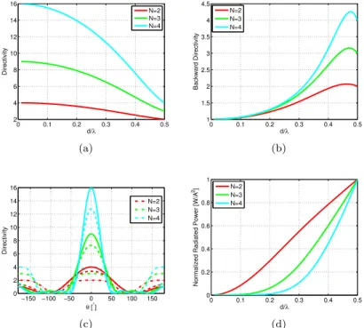
fixed spacing, increasing the number of the elements significantly increases the excitation magnitudes. By applying this excitation coefficients, the maximum directivity that can be obtained as a function of the inter-element distance is given in Figure 3(a). It may be noted that when the distance between the elements approaches zero the array directivity approaches N2. Increasing the 60
spacing decreases the directivity in the main direction and increases it the bac-kward direction (Figure 3(b)). At 0.5λ the directivity in both end-fire directions are equal to N (refer to Figure 3(c)). Figure 3(d) shows the power radiated by the array for normalized excitation coefficients power, i.e (∑Nn=1A2
n= 1). This
power is calculated as follows:
65 Prad= 1 2 ‹ S Re(E× H∗).ds≈ 1 2η ‹ S |E|2ds≈ 1 2η ˆ 2π 0 ˆ π 0 |E|2r2sin(θ) dθ dϕ (5) 3
0 0.1 0.2 0.3 0.4 0.5 0.8 1 1.2 1.4 1.6 1.8 2 d/λ Magnitude [A] A1 A2 A3 (a) 0 0.1 0.2 0.3 0.4 0.5 −50 0 50 100 150 200 d/λ Phase [ °] Φ1 Φ2 Φ3 (b)
Figure 1: Three d-spaced isotropic array optimal excitation coefficients. (a) Magnitude and (b) phase. 0 0.1 0.2 0.3 0.4 0.5 0.5 1 1.5 2 2.5 3 d/λ Magnitude [A] A1 A2 A3 A4 (a) 0 0.1 0.2 0.3 0.4 0.5 −50 0 50 100 150 200 d/λ Phase [ °] Φ1 Φ2 Φ3 Φ4 (b)
Figure 2: Four d-spaced isotropic array optimal excitation coefficients. (a) Magnitude and (b) phase.
where η is intrinsic impedance of the medium (air), r is the radius of the sphere over-which the radiated power is calculated and E is the total far-field electric field and can be calculated as in Equation (1). We can notice that, for the same distance, as the number of the elements increases, the radiated power decreases, and as a consequent, so does the array radiation efficiency. To study
70
the sensitivity of the array toward the excitation coefficients, we re-calculated the directivity when the coefficients magnitudes are estimated with an error of 5% or the phases are shifted by 5o. Figure 4 shows the obtained results (since
the symmetric elements have equal magnitudes, the array sensitivity toward the errors in these elements excitation is also the same, so they are not shown). It
75
may be noted that, for small spacing, the array is very sensitive to the changes in the coefficients. It is also possible to notice that, for a fixed distance, increasing the number of the elements increases the array sensitivity. For a distance d = 0.1λ an error of 5% in the estimation of first element magnitude reduces the directivity by 1.1%, 10.2% or 56.1% in case of an array of two-, three- or
four-80
0 0.1 0.2 0.3 0.4 0.5 2 4 6 8 10 12 14 16 d/λ Directivity N=2 N=3 N=4 (a) 0 0.1 0.2 0.3 0.4 0.5 1 1.5 2 2.5 3 3.5 4 4.5 d/λ Backward Directivity N=2 N=3 N=4 (b) −150 −100 −50 0 50 100 150 0 2 4 6 8 10 12 14 16 θ [°] Directivity N=2 N=3 N=4 (c) 0 0.1 0.2 0.3 0.4 0.5 0 0.2 0.4 0.6 0.8 1 d/λ
Normalized Radiated Power [W/A
2] N=2
N=3 N=4
(d)
Figure 3: The performance of N-element d-spaced isotropic array. (a) The directivity in the main end-fire direction (b) the directivity in the backward en-fire direction, (c) the 2D total directivity radiation pattern for d=0.01 (continuous), d=0.25 (dashed) and d=0.01 (dashed-dotted), and (d) the normalized transmitted power.
array is more sensitive to the changes in the coefficients of the middle elements. This is due to the fact that the magnitudes of these coefficients are higher. After presenting the the theoretical limits of superdirective arrays, in the next section we will show some practical limits via the design of a three-element array.
85
3. Three-Element Array Design
The superdirective antenna array design methodology detailed in [17] was used to design a three-element array. The unit-element used in this array is a miniaturized half-loop antenna printed on a 0.8mm-thick Rogers RO4003 sub-strate and integrated in a PCB of 8× 8cm2 [18]. It has a resonance frequency
90
around 864M Hz with a directivity of 2.4dBi and radiation efficiency of 89.4%. The proposed antenna geometry is shown in Figure 5(a). The inter-element distance d1 is varied from 0.69cm ≈ 0.02λ to 6cm ≈ 0.17λ to investigate its
effect on the antenna maximum directivity and radiation efficiency. Figure 5(b) shows the array directivity compared to Harrington’s fundamental limit on
di-95
rectivity of an antenna with the same size ka given by D = (ka)2+ 2ka [6].
As expected, it can be noticed that for very small distances the driven array
0 0.1 0.2 0.3 0.4 0.5 1.5 2 2.5 3 3.5 4 d/λ Maximum Directivity Optimal A1±5% Φ1±5 o (a) 0 0.1 0.2 0.3 0.4 0.5 0 2 4 6 8 d/λ Maximum Directivity Optimal A 1±5% A 2±5% Φ1±5 o Φ2±5o (b) 0 0.1 0.2 0.3 0.4 0.5 0 5 10 15 d/λ Maximum Directivity Optimal A 1±5% A2±5% Φ1±5o Φ2±5o (c)
Figure 4: The effect of the error in the coefficients estimation on the directivity of N-element
d-spaced isotropic array. (a) N=2, (b) N=3 and (c) N=4.
is very sensitive toward the excitation coefficients and a small error in the cal-culation of these coefficients leads to an important decrement in the antenna directivity. As the distance increases, this sensitivity decreases and starting
100
from d1 = 3.5cm ≈ 0.08λ interesting directivities can be attained. The value
(a) 0 0.05 0.1 0.15 0.2 4 5 6 7 8 9 10 Dmax [dBi] d1/λ Harrington limit Driven Parasitic (b)
Figure 5: Proposed superdirective array. (a) Array geometry and (b) simulated total directi-vity.
Figure 6. As it can be noticed, some negative resistances are required, and since the design of negative resistances using non-Foster circuits is not an easy task, neglecting these resistances significantly decreases the attained directivity
105
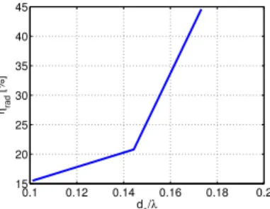
compared to the fully-driven array. Finally, Figure 7 shows that, as expected due to the coupling decrement, the parasitic array radiation efficiency incre-ases with the inter-element distance. A prototype of the antenna array for
0.1 0.12 0.14 0.16 0.18 0.2 −50 −40 −30 −20 −10 0 10 20 Ri [ Ω ] d1/λ i=1 i=2 i=3 (a) 0.1 0.12 0.14 0.16 0.18 0.2 −80 −60 −40 −20 0 20 40 60 Xi [ Ω ] d1/λ i=1 i=2 i=3 (b)
Figure 6: The value of the required loads for converting the array to a parasitic one. (a) Real part and (b) imaginary part.
0.1 0.12 0.14 0.16 0.18 0.2 15 20 25 30 35 40 45 ηrad [%] d 1/λ
Figure 7: Parasitic array simulated radiation efficiency.
d1 = 6cm ≈ 0.17λ was fabricated and measured (Figure 8(a)). In this array,
the second element is excited while the others are loaded. Figure 8(b) shows
110
the antenna input reflection coefficient magnitude in dB. As it can be noti-ced, the antenna has a simulated/measured resonance at 863/868M Hz with a
S11<−10dB bandwidth of 1.7/5MHz. The higher losses in the measurement
may be attributed to the UFL cable used in measurement. Figure 8(c) shows the antenna 3D total directivity radiation pattern. The figure shows a directive
115
pattern with a directivity of 8.8/8.5dBi toward z-axis. This directivity is about 1.4dB greater than Harrington’s normal directivity limit for an antenna with the same size factor (ka = 1.6). The HPBW in E (XoZ) and H (YoZ) planes are respectively 72o/73.1o and 64o/67.5o and FBR is 5.8dB/4.1dB (Figure 9).
The antenna presents a radiation efficiency of 34.7%/37%.
120
(a) 0.8 0.85 0.9 0.95 1 −25 −20 −15 −10 −5 0 X: 0.863 Y: −16.47 Frequency [MHz] S11 [dB] X: 0.868 Y: −22.15 Simulated Measured (b) Simulated Measured (c)
Figure 8: Three-element array with 6cm spacing simulated and measured parameters. (a) Fa-bricated prototype, (b) input reflection coefficient magnitude in dB and (c) 3D total directivity radiation pattern. −10 0 10 30 210 60 240 90 270 120 300 150 330 180 0 θ [°] Directivity [dBi] Simulated Measured (a) −10 0 10 30 210 60 240 90 270 120 300 150 330 180 0 θ [°] Directivity [dBi] Simulated Measured (b)
Figure 9: Three-element array with 6cm spacing simulated and measured parameters 2D total directivity radiation patterns. (a) E-plane, (b) H-plane.
4. Conclusion
In this article, we have shown the theoretical and practical limits on super-directive antenna arrays design. These limits can be summarized by the array
sensitivity toward the excitation coefficients and the small efficiencies for very closely-spaced arrays and the need for negative resistances for transforming the
125
arrays to parasitic ones. In general, superdirective antenna arrays design is a trade-off between the antenna dimensions (the number of the elements and the inter-element distance) and the attained- directivity and -efficiency. By a ca-reful consideration of these trade-offs superdirective yet efficient arrays can be designed.
130
Acknowledgments
This work was done with the funding of the French National Research Agency as part of the project "SOCRATE" and the support of the "Images et Reseaux" cluster of Brittany region, France.
References
135
[1] Ick-Jae Yoon, Realizing Efficient Wireless Power Transfer in the Near-Field Region Using Electrically Small Antennas (PhD dissertation), The Univer-sity of Texas at Austin, 2012. Available: http://hdl.handle.net/2152/ ETD-UT-2012-08-6167
[2] H. A. Wheeler, Fundamental Limits of Small Antennas, Proceedings of The
140
I.R.E. (IEEE), pp. 1479-1484, Dec. 1947.
[3] H. A. Wheeler, The Radiansphere Around a Small Antenna, Proceedings of The I.R.E. (IEEE), vol. 47, Aug. 1959.
[4] L. .J. Chu, "Physical Limitations of OmniDirectional Antennas", Journal of Applied Physics, vol. 19, no. 12, pp. 1163-1175, 1948.
145
[5] R. M. Fano, Theoretical Limitations on the Broadband Matching of Arbi-trary Impedances, J. Franklin Institution, vol. 249, pp. 57-83 and 139-155, Jan. and Feb. 1950.
[6] R. F. Harrington, On the Gain and Beamwidth of Directional Antennas, IRE Transactions on Antennas and Propagation, pp. 219-225, Jul. 1958.
150
[7] I. Uzkov, An Approach to the Problem of Optimum Directive Antennae Design, C. R. de l’académie des sciences de l’URSS, vol. 53, no. 1, 1946. [8] E. E. Altshuler et al., A Monopole Superdirective Array, IEEE Trans. on
Ant. Propag., vol. 53, no. 8, pp. 2653-2661, Aug. 2005.
[9] T. H. O’Donnell, and A. D. Yaghjian, Electrically Small Superdirective
Ar-155
rays Using Parasitic Elements, IEEE Ant. and Propag. Soc. Int. Symp., pp. 3111,3114, 9-14 Jul. 2006.
[10] T. H. O’Donnell et al., Frequency Optimization of Parasitic Superdirective Two Element Arrays, IEEE Ant. and Propag. Soc. Int. Symp., pp. 3932,3935, 9-15 June 2007.
160
[11] S. Lim, and H. Ling, Design of Electrically Small Yagi Antenna, Electronics Lett., vol. 43, no. 5, pp.3-4, 1 Mar. 2007.
[12] A. D. Yaghjian et al., Electrically Small Supergain End-Fire Arrays, Radio Science, vol. 43, 2008.
[13] O. S. Kim et al., Superdirective Magnetic Dipole Array as a First-Order
165
Probe for Spherical Near-Field Antenna Measurements, IEEE Trans. on Ant. Propag., vol. 60, no. 10, pp.4670-4676, Oct. 2012.
[14] B. Sentucq et al., Superdirective Compact Parasitic Array of Metamaterial-Inspired Electrically Small Antenna, Int. Work. on Ant. Tech. (iWAT), pp. 269,272, 4-6 Mar 2013.
170
[15] M. Pigeon et al., Miniature and Superdirective Two Elements Endfire An-tenna Array, Eur. Conf. on Ant. and Propag. (EuCAP 2014), 6-11 Ap. 2014. [16] A. Clemente et al., Design of a Super Directive Four-Element Compact An-tenna Array Using Spherical Wave Expansion, IEEE Trans. on Ant. Propag., vol. 63, no. 11, pp. 4715-4722, Nov. 2015.
175
[17] A. Haskou et al., Design of Small Parasitic Loaded Superdirective End-Fire Antenna Arrays, IEEE Trans. on Ant. and Propag., vol. 63, no. 12, pp. 5456-5464, Dec. 2015.
[18] A. Haskou et al., Compact Planar Arrays Based on Parasitic Superdirective Elements, Eur. Conf. on Ant. and Propag. (EuCAP 2016), 10-15 Ap. 2016.