HAL Id: hal-02360683
https://hal.archives-ouvertes.fr/hal-02360683
Submitted on 7 Jul 2020
HAL is a multi-disciplinary open access
archive for the deposit and dissemination of
sci-entific research documents, whether they are
pub-lished or not. The documents may come from
teaching and research institutions in France or
abroad, or from public or private research centers.
L’archive ouverte pluridisciplinaire HAL, est
destinée au dépôt et à la diffusion de documents
scientifiques de niveau recherche, publiés ou non,
émanant des établissements d’enseignement et de
recherche français ou étrangers, des laboratoires
publics ou privés.
Compact Four-Element Phased Antenna Array for 5G
Applications
Muhammad Kamran Ishfaq, Tharek Abd Rahman, Mohamed Himdi, Hassan
Tariq Chattha, Yasir Saleem, Bilal Khawaja, Farhan Masud
To cite this version:
Muhammad Kamran Ishfaq, Tharek Abd Rahman, Mohamed Himdi, Hassan Tariq Chattha, Yasir
Saleem, et al.. Compact Four-Element Phased Antenna Array for 5G Applications. IEEE Access,
IEEE, 2019, 7, pp.161103-161111. �10.1109/ACCESS.2019.2949149�. �hal-02360683�
Received September 17, 2019, accepted October 8, 2019, date of publication October 23, 2019, date of current version November 14, 2019. Digital Object Identifier 10.1109/ACCESS.2019.2949149
Compact Four-Element Phased Antenna Array
for 5G Applications
MUHAMMAD KAMRAN ISHFAQ1, THAREK ABD RAHMAN2, MOHAMED HIMDI 3, HASSAN TARIQ CHATTHA 4, (Senior Member, IEEE), YASIR SALEEM5,
BILAL A. KHAWAJA 4,6, (Senior Member, IEEE), AND FARHAN MASUD7
1Department of Electrical Engineering, Government College University Faisalabad, Faisalabad 38000, Pakistan 2Wireless Communication Centre, Universiti Teknologi Malaysia (UTM), Johor Bahru 81310, Malaysia 3Institut d’Electronique et Télécommunications de Rennes, University of Rennes 1, 35000 Rennes, France
4Department of Electrical Engineering, Faculty of Engineering, Islamic University of Madinah, AlMadinah 41411, Saudi Arabia 5Department of Computer Science and Engineering, University of Engineering and Technology (UET), Lahore, Lahore 54890, Pakistan
6Department of Electronic and Power Engineering (EPE), PN-Engineering College (PNEC), National University of Sciences and Technology (NUST),
Karachi 75104, Pakistan
7Department of Statistics and Computer Science, University of Veterinary and Animal Sciences, Lahore 54000, Pakistan
Corresponding authors: Muhammad Kamran Ishfaq ([email protected]) and Hassan Tariq Chattha ([email protected])
This work was supported by the Deanship of Scientific Research, Islamic University of Madinah, Saudi Arabia, under Grant 16/40.
ABSTRACT This paper presents a four-element compact phased Planar Inverted-E Antenna (PIEA) array for 6 GHz beamforming applications. For compact phased arrays, the mutual coupling is a severe performance degrading factor. Therefore, three mutual coupling reduction techniques are employed, which include (i) PIEA as an array element which is a modified version of Planar Inverted-F Antenna (PIFA) by inserting another shorting plate, (ii) slots in the ground plane and (iii) two slits in each etched ground slot. With these techniques, the mutual coupling is reduced below −19 dB in the operational bandwidth from 5.7 to 6.4 GHz. The compact design with an inter-corner spacing of 0.013λo and an inter-element spacing of 0.3λo is
achieved. The peak gain obtained by this compact phased array is 8.36 dBi. This array can scan up to a maximum scanning angle of ±70o. A good general agreement is found between the measured and simulated results.
INDEX TERMS Antennas, phased array, PIFA, beamforming, mutual coupling.
I. INTRODUCTION
5G represents a revolution in telecommunication, which will bring a paradigm shift in the way we communicate for the years to come [1]. It will provide a data rate up to 10 Gbps, fibre-like user experience, 1 ms over-the-air latency, user capacity up to several billion, and many more [2], [3]. For achieving this greater capacity, a large bandwidth is needed. Hence, 5G is looking beyond the presently used 3 GHz spectrum band. The spectrum of 3–30 GHz is referred to as microwave while 30-300 GHz is referred to as the millimetre-wave (mm-millimetre-wave) bands. In recent years, studies for the next-generation wireless communication systems have begun to shift from UHF frequencies (i.e. 300 MHz-3 GHz) to the new spectrum in the microwave range, including mm-wave spectrums. Currently, the spectrum below 6 GHz is
The associate editor coordinating the review of this manuscript and approving it for publication was Qammer Hussain Abbasi .
not enough to meet future needs, which means that new spectrum allocations in the mm-wave frequency bands above 6 GHz are required to alleviate the current spectrum short-age. This is the primary driver in the development of fifth generation (5G) wireless communication systems. Hence, the microwave range above 6 GHz and mm-wave bands are the primary keys for resolving 5G challenges. Due to the increase in the number of subscribers and the need for high data-rate in wireless communication systems, the demands for an increase in channel capacity, mitigation of multi-path fading, and co-channel interference are paramount for mobile and satellite communication systems. As the number of users increases, the co-channel interference also increases that leads to poor Quality of Service (QoS). This has trig-gered a lot of research effort in the area of phased arrays to tackle this problem and improve the quality of communi-cation even in unfavourable conditions. On the other hand, electronic gadgets are becoming more and more compact.
M. K. Ishfaq et al.: Compact Four-Element Phased Antenna Array for 5G Applications
Therefore, designing compact antennas and arrays with enhanced performance poses a challenge for the antenna design researchers [4]–[6]. Small cell base stations will require a compact beamforming antenna array. Thereby, the researchers have proposed different approaches for designing compact beamforming arrays such as a beam-switching array using Yagi-like parasitic elements and employing complex mutual compensation algorithms [7], [8]. The task of designing a compact beamforming array is also a challenge due to the mutual coupling being a severe per-formance degrading factor. The effects of mutual coupling intensify as the inter-element spacing is reduced.
Planar Inverted-F Antenna (PIFA) has been a very popular candidate in portable wireless systems due to its appealing characteristics, such as low-profile, ease of fabrication and robustness etc. [9], [10]. Also, it does not require any match-ing network when connected to the 50 coaxial input [11]. It is also a suitable candidate for building compact arrays because it is comparatively less affected by another neigh-bouring PIFA [4], [12]–[15]. In the literature, few PIFA anten-nas and arrays are reported for 5G applications [15]–[20]. An 8-element phased array using open-slot PIFA antenna at mm-wave is designed for beamforming applications with an inter-element spacing of half a wavelength, reporting only simulated results [15]. In [16], a 4-element MIMO PIFA array is presented at 28 GHz. Three MIMO array models/arrangements are presented using space diversity where each element is located in a different arrangement with an inter-element spacing of half a wavelength [16]. A two-element MIMO antenna in which the elements are in anti-parallel arrangement facing each other is reported in [17] having an inter-element spacing of more than half a wavelength. Further, in [18], a three-element MIMO PIFA design is proposed with each element in a different direction/ arrangement, but no fabrication is reported. However, this MIMO antenna also has half a wavelength inter-element spacing. Another six-element MIMO PIFA was reported and designed at 28 GHz in [19]. In this design, the PIFA elements were arranged in different directions using space diversity with an inter-element spacing of half a wavelength [19].
In this paper, a design of compact phased array using Planar Inverted-E Antenna (PIEA) elements is presented having a resonant frequency of 6 GHz, by employing three mutual coupling reduction techniques, which are: dual-shorting pins, thus making it a PIEA instead of a PIFA, ground slots in-between adjacent array elements and two slits in each of these slots with an inter-element spacing of 0.3λo(whereλo=λ at
6 GHz = 50 mm).
The rest of the paper is organized as follows: Section 2 dis-cusses the proposed array configuration. Section 3 presents the antenna array design approach using a parametric study. Section 4 compares the simulated and measured results, whereas Section 5 discusses the beam steering capabilities of the designed antenna array, and finally, Section 6 draws conclusions.
II. ARRAY CONFIGURATION
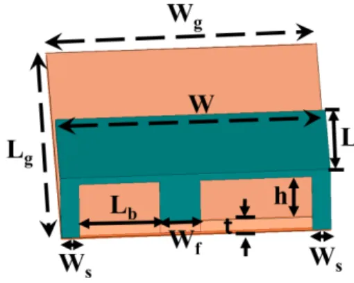
Fig. 1 shows the configuration of a single dual-shorting PIFA element, thus becoming a PIEA. It consists of a ground plane with dimensions Lg× Wg. The PIEA top plate has dimensions
of W × L, while the antenna height is h. The two shorting plates of width Wsare located on each corner of the top edge
of the antenna. Table 1 shows the optimised values of the design parameters of a single PIEA element.
FIGURE 1. Single Planar Inverted-E Antenna (PIEA).
TABLE 1.Parameters of a PIEA.
Fig. 2 shows the 3D view and back view of the compact antenna array having four PIEA elements. The inter-element and the inter-corner spacings are d and Serespectively. The
ground slots are introduced in-between the adjacent array elements with a width equal to the inter-corner spacing of adjacent elements i.e. Se. Further, two slits named Gslt1and Gslt2are added in each of these slots at distances Ycand Yst,
respectively from the upper edge of the array. The widths of slots Gslt1 and Gslt2 are Wst and Wc respectively. The
dielectric material used is Roger RT/Duriod 5880 having a thickness t = 0.5 mm and a relative permittivity εr = 2.2.
Table 2 shows the optimised values of the design parameters of the compact PIEA array.
III. ARRAY DESIGN APPROACH USING PARAMETRIC STUDY
The compact array is developed by employing the design approach given as under:
1. Dual-shorting pin PIFA antenna, i.e. PIEA being more suitable regarding reducing mutual coupling explained in detail in the next section.
FIGURE 2. Compact phased PIEA Array (a) 3D view, (b) Bottom view.
TABLE 2. Parameters of compact PIEA array.
2. Introducing a ground slot between the adjacent array elements.
3. Introducing a slit in the ground slots at a distance Ycfrom
the upper edge of the array.
4. Introducing another slit in the ground slots at a distance
Ystfrom the upper edge of the array.
A. SINGLE ELEMENT ANTENNA DESIGN AND PARAMETRIC STUDY
The single-element PIEA is designed by applying parametric study approach to study the effects of antenna parameters on its performance. After observing the effects of all parameters, the design is optimised by using the Particle Swarm Optimisa-tion (PSO) algorithm approach. The CST Microwave Studio (v. 2016) simulation software is used for this purpose.
The width W of the top plate of PIEA is changed from 12 mm to 15 mm, while other parameters are held constant at Wf =2 mm, h = 1.9 mm, L = 7.5 mm, Wg = 14 mm and Lg =22.5 mm. Figure 3 shows that the resonant frequency is inversely proportional to the width of the top plate as its value is decreased with an increase in the width. The width of nearly 14 mm is found to be suitable for the design. Further, the length L of the top plate of PIEA is varied while other parameters are held constant. Similar to the width of the top plate, it is found by the parametric study that the increase in the length of the top plate decreases the resonant frequency as being inversely proportional to each other.
FIGURE 3. Parametric study for width W of the top plate of PIEA.
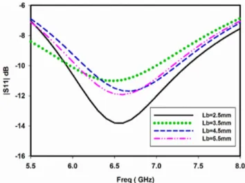
Next, the distance of the feeding plate from the shorting plate i.e. Lbis changed from 2.5 mm to 5.5 mm while other
parameters are held constant. Fig. 4 shows that the Lb is
an important parameter for obtaining the matching, and its value in the range of 3.5 to 4.5 mm can achieve the required resonant frequency.
FIGURE 4. Parametric study for distance Lbof feeding plate from shorting plate.
Further, the feeding plate width of the PIEA i.e Wf is
varied from 2 mm to 6 mm, while other parameters are held constant. The results in Fig. 5 suggest that the feed plate width affects the matching as well as the overall antenna bandwidth. The increase in feed width increases the bandwidth. Finally, with the values obtained from the comprehensive parametric study, the optimisation is performed by using the PSO algo-rithm. The optimised design values of single PIEA element are given in Table 1 as shown in the previous section.
B. ARRAY DESIGN AND PARAMETRIC STUDY
Like the single element PIEA, a parametric study is carried out to get an understanding of the behavior of different parameters and for obtaining the right size and positions of
M. K. Ishfaq et al.: Compact Four-Element Phased Antenna Array for 5G Applications
FIGURE 5. Parametric study for the width of the feeding plate Wf.
these different parameters for reducing the mutual coupling between array elements. In the parametric study, the same approach of changing one parameter at a time while others being held constant at the values provided in Table 2. When the position of Gslit1from the upper edge of the ground plane,
i.e. Ycis varied from 14 mm to 20 mm, it is observed that it
significantly affects the values of S22and S12but not affecting
much to that of S11,where S11and S22 are reflection
coeffi-cients of PIEA elements 1 and 2 respectively and S12being the
mutual coupling between these two elements. Therefore, the results related to S22and S21= S12are shown in Fig. 6. It is
evident from the results shown that the value of Ycbetween
18 to 20 mm would show better performance in terms of S22
and the reduced mutual coupling effect i.e. enhanced isolation between the two elements.
Similarly, Fig. 7 shows the effects of changing the position of Gslit2from the upper edge of the array i.e. Yst on mutual
coupling S21. It is evident from the figure that the insertion
of slit Gslit2 and small variation in its position significantly
affects the mutual coupling S21. And its appropriate position
is required to achieve the maximum isolation between the two elements. An addition of slits at the position Yc and Yst
jointly create a long slot in the ground plane, which blocks the coupling currents.
Finally, the inter-element spacing i.e. d is varied to obtain a compact design. In Fig. 8, the inter-element spacing d is varied from 15 mm to 25 mm with a step of 2 mm while all other parameters are unchanged. It is clear from the Fig-ure that increasing the distance between elements increases the isolation but since we need a compact design, we need to have a minimum distance with the acceptable value of iso-lation. As the figure depicts that at an inter-element spacing of 0.3λ i.e. d = 15 mm, still provides good results with regards to isolation i.e. below −15 dB. Therefore, the separation
d =15 mm is suitable for the compact array design. After iterative simulations, parametric studies and intro-ducing mutual coupling reduction techniques described above, the inter-element spacing i.e d is achieved to be just
FIGURE 6. Parametric study of Position of Gslt 1i.e. Ycin the ground
plane (a) S22(dB) (b) S21(dB).
FIGURE 7. Effects of position variation of Gslt 2i.e. Yston S21(dB).
0.3λ = 15 mm whereas the inter-corner distance i.e. Se is
just 0.65 mm = 0.013λo while maintaining good isolation
between antenna elements.
IV. RESULTS AND DISCUSSION
The simulated reflection coefficient S11 in dB for single
element PIEA is presented in Fig. 9. The results show that it
FIGURE 8. Parametric study for observing the effects of inter-element spacing d on S21(dB).
FIGURE 9. Simulated S11[dB] of single element PIEA.
is a wideband design with a frequency ranging from 5.7 GHz to around 6.8 GHz for S11 < −10 dB. It is found to have
an adequate simulated gain of 4 dBi at 6 GHz. This PIEA antenna is compact and low-profile as the height of this antenna is just 1.8 mm. Secondly, it shows an inherent mutual coupling reduction capability when used as an array element which is shown in the compact phased array design.
Fig. 10 shows the fabricated prototype of 4-element com-pact phased PIEA array. Figure 11 shows the simulated and measured s-parameters of the proposed compact PIEA array,
FIGURE 10. Fabricated prototype of 4-Element compact phased PIEA array.
FIGURE 11. S-parameters of the compact phased PIEA Array (a) simulated, (b) measured.
which confirms that the array is well matched and present a low mutual coupling between the ports, from 5.7 GHz to 6.4 GHz. The design achieves excellent performance with the use of the proposed methods, having isolation better than −19 dB in the operational bandwidth. The current distribu-tions in Fig. 12 shows that shorting pins on both sides of the PIEA forms a built-in folded slot antenna in between,
M. K. Ishfaq et al.: Compact Four-Element Phased Antenna Array for 5G Applications
TABLE 3. Comparison with previous work.
FIGURE 13. Simulated 3D pattern having thebeam-steering capability at 20◦, 40◦, and 70◦.
which cause the coupling energy to radiate in the air and hence reduce the mutual coupling. Also, the slots between array elements, along with the two slits in each slot, block
the coupling currents in the ground plane. The position of
Yst decides the size of the folded slot antenna which affects
the mutual coupling. Despite that, the mutual coupling is below −19 dB, which represents the effectiveness of applied techniques.
V. BEAM STEERING CAPABILITY
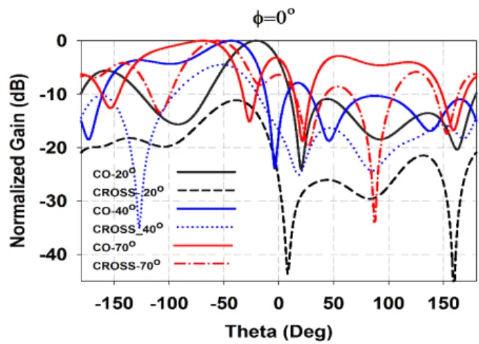
Figure 13 shows the simulated 3D radiations patterns having the beam-steering capability at 20◦, 40◦, and 70◦.
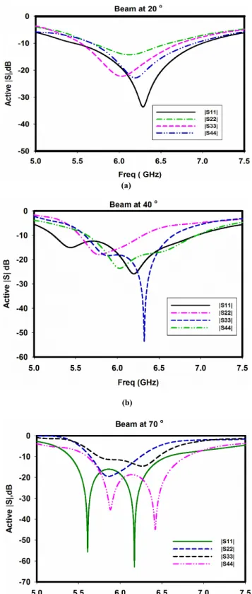
The beam at 40ois providing a 3-dB scanning range of 70o, while the beam at 70ois providing a scanning range up to 90o. Figure 14 shows the measured 2D beam-steering capability at three angles by applying the adequate phase shifts between elements to have 20o, 40o, 70o beams with the peak gain of 8.13 dBi, 6.8 dBi and 3.1 dBi respectively. The loss in gain is higher at far-angle due to higher cross-polarization as well as higher sidelobe levels at that angle. The results of active-S parameters in Fig. 15 show that the array is well-matched throughout the scanning range.
FIGURE 14. Measured 2D beam-steering capability at 20◦, 40◦, and 70◦.
Since only a few compact PIFA phased arrays exist in the literature, therefore, the comparison of the proposed work is made with DRA-type compact phased array and a PIFA array for mobile applications. Table 3 shows the comparison between previous works on the compact arrays and the pro-posed design presented in this paper. The design presented in [8] is compact as having an inter-element spacing of 0.32λ, but it has limited scanning range and lower bandwidth. The design shown in [7], is bigger as inter-element spacing is 0.4λ
FIGURE 15. Active S-parameters for scanning angles, (a) 20◦, (b) 40◦,
(c) 70◦.
and also it has limited scanning range. Further, the design in [15] is bigger as inter-element spacing equals 0.5λ, and has a scanning range of up to 600while no fabrication is done.
In comparison to these works, the proposed design is more compact with an inter-element spacing of just 0.3λ and has a scanning range of up to 70o.
VI. CONCLUSION
In this paper, a compact phased PIEA array has been proposed, designed, fabricated and characterised for the upcoming 5G applications. Since the mutual coupling is a severe performance degrading factor in compact phased arrays, hence three mutual coupling reduction techniques are employed. With these mutual coupling reduction techniques, compact phased PIEA array with an inter-element spacing of 0.3λo is achieved which can work from 5.7 GHz to
6.4 GHz, with a maximum beam scanning angle of ±70o. However, the cross-polarization and sidelobe level are higher at far beams which will be addressed in the future work.
REFERENCES
[1] S. Malkowsky, J. Vieira, L. Liu, P. Harris, K. Nieman, N. Kundargi, I. C. Wong, F. Tufvesson, V. Öwall, and O. Edfors, ‘‘The World’s first real-time testbed for massive MIMO: Design, implementation, and validation,’’ IEEE Access, vol. 5, pp. 9073–9088, 2017.
[2] J. G. Andrews, S. Buzzi, W. Choi, S. V. Hanly, A. Lozano, A. C. K. Soong, and J. C. Zhang, ‘‘What will 5G be?’’ IEEE J. Sel. Areas Commun., vol. 32, no. 6, pp. 1065–1082, Jun. 2014.
[3] G. Fettweis and S. Alamouti, ‘‘5G: Personal mobile Internet beyond what cellular did to telephony,’’ IEEE Commun. Mag., vol. 52, no. 2, pp. 140–145, Feb. 2014.
[4] H. Li, B. K. Lau, and S. He, ‘‘Design of closely packed pattern recon-figurable antenna array for MIMO terminals,’’ IEEE Trans. Antennas Propag., vol. 65, no. 9, pp. 4891–4896, Sep. 2017.
[5] W. Qiao, X. Gao, X. Yu, S. M. Li, Y.-N. Jiang, and H.-F. Ma, ‘‘Ultra-compact microstrip antenna array and miniaturized feeding network,’’ Prog. Electromagn. Res., vol. 71, pp. 111–122, Feb. 2017.
[6] Y. Li, C.-Y.-D. Sim, Y. Luo, and G. Yang, ‘‘12-Port 5G massive MIMO antenna array in Sub-6GHz mobile handset for LTE bands 42/43/46 appli-cations,’’ IEEE Access, vol. 6, pp. 344–354, 2017.
[7] N. H. Shahadan, M. H. Jamaluddin, M. R. Kamarudin, Y. Yamada, M. Khalily, M. Jusoh, and S. H. Dahlan, ‘‘Steerable higher order mode dielectric resonator antenna with parasitic elements for 5G applications,’’ IEEE Access, vol. 5, pp. 22234–22243, 2017.
[8] J. Nasir, M. H. Jamaluddin, M. R. Kamarudin, I. Ullah, Y.-C. Lo, and R. Selvaraju, ‘‘A four-element linear dielectric resonator antenna array for beamforming applications with compensation of mutual coupling,’’ IEEE Access, vol. 4, pp. 6427–6437, 2016.
[9] H. T. Chattha, Y. Huang, Y. Lu, and X. Zhu, ‘‘An ultra-wideband pla-nar inverted-F antenna,’’ Microw. Opt. Technol. Lett., vol. 52, no. 10, pp. 2285–2288, Oct. 2010.
[10] H. T. Chattha, M. K. Ishfaq, Y. Saleem, Y. Huang, and S. J. Boyes, ‘‘Band-notched ultrawide band planar inverted-F antenna,’’ Int. J. Anten-nas Propag., vol. 2012, Apr. 2012, Art. no. 513829.
[11] H. Yi and K. Boyle, Antennas: From Theory to Practice, 1st ed. Hoboken, NJ, USA: Wiley, 2008.
[12] Y. Gao, X. Chen, Z. Ying, and C. Parini, ‘‘Design and performance investi-gation of a dual-element PIFA array at 2.5 GHz for MIMO terminal,’’ IEEE Trans. Antennas Propag., vol. 55, no. 12, pp. 3433–3441, Dec. 2007. [13] T. Kokkinos, E. Liakou, and A. P. Feresidis, ‘‘Decoupling antenna elements
of PIFA arrays on handheld devices,’’ Electron. Lett., vol. 44, no. 25, pp. 1442–1444, Dec. 2008.
[14] D. W. Browne, M. Manteghi, M. P. Fitz, and Y. Rahmat-Samii, ‘‘Exper-iments with compact antenna arrays for MIMO radio communica-tions,’’ IEEE Trans. Antennas Propag., vol. 54, no. 11, pp. 3239–3250, Nov. 2006.
[15] M. Stanley, Y. Huang, T. Loh, Q. Xu, H. Wang, and H. Zhou, ‘‘A high gain steerable millimeter-wave antenna array for 5G smartphone applications,’’ in Proc. 11th Eur. Conf. Antennas Propag., Mar. 2017, pp. 1311–1314.
M. K. Ishfaq et al.: Compact Four-Element Phased Antenna Array for 5G Applications
[16] S. Dutta, T. Sanguankotchakorn, and N. Daloi, ‘‘Modeling of 4-element planar inverted F-antenna array for 5G applications,’’ in Proc. 2nd IEEE Int. Conf. Recent Trends Electron., Inf. Commun. Technol., May 2017, pp. 1271–1275.
[17] H. M. R. Nurul, Z. Mansor, and M. K. A. Rahim, ‘‘Dual element MIMO planar inverted-F antenna (PIFA) for 5G millimeter wave application,’’ Telkomnika, vol. 17, no. 4, pp. 1648–1655, 2019.
[18] O. M. Haraz, M. Ashraf, and S. Alshebeili, ‘‘Single-band PIFA MIMO antenna system design for future 5G wireless communication applica-tions,’’ in Proc. IEEE 11th Int. Conf. Wireless Mobile Comput., Netw. Commun., Oct. 2015, pp. 608–612.
[19] Y. A. M. K. Hashem, O. M. Haraz, and E. D. M. El-Sayed, ‘‘6-Element 28/38 GHz dual-band MIMO PIFA for future 5G cellular systems,’’ in Proc. IEEE Int. Symp. Antennas Propag., Jun./Jul. 2016, pp. 393–394. [20] M. K. Ishfaq, T. Abd Rahman, H. T. Chattha, and M. Ur Rehman,
‘‘Multiband split-ring resonator based planar inverted-F antenna for 5G applications,’’ Int. J. Antennas Propag., vol. 2017, no. 1, Mar. 2017, Art. no. 5148083.
MUHAMMAD KAMRAN ISHFAQ received the bachelor’s and master’s degrees in electrical engi-neering from the University of Engiengi-neering and Technology Lahore, in 2005 and 2011, respec-tively, and the Ph.D. degree in phased arrays and multibeam antennas for 5G from the Wire-less Communication Centre, Universiti Teknologi Malaysia, in 2018. He is currently an Assistant Professor with the Department of Electrical Engi-neering, Government College University Faisal-abad, Pakistan. He has authored and coauthored journal and conference papers in the field of antennas, electrical and computer science. His current research interests include antennas, phased arrays, microwave systems, and computer networks.
THAREK ABD RAHMAN received the B.Sc. degree in electrical and electronic engineering from the University of Strathclyde, U.K., in 1979, the M.Sc. degree in communication engineering from UMIST, Manchester, U.K., and the Ph.D. degree in mobile radio communication engineer-ing from the University of Bristol, U.K., in 1988. He is currently a Professor with the Faculty of Electrical Engineering, Universiti Teknologi Malaysia (UTM), where he is also the Director of the Wireless Communication Centre (WCC). He has been conducting various short courses related to mobile and satellite communication to the Telecom-munication Industry and Government body, since 1990. He has a teaching experience in the area of mobile radio, wireless communication systems, and satellite communication. He has published more than 120 articles related to wireless communication in national/international journal and conference. His current research interests include radio propagation, antenna and RF design, and indoors and outdoors wireless communication.
MOHAMED HIMDI received the Ph.D. degree in signal processing and telecommunications from the University of Rennes 1, Rennes, France, in 1990. Since 2003, he has been a Professor with the University of Rennes 1. He is currently the Head of the Center National de la Recherche Scienti_que, High Frequency and Antenna Depart-ment, Institut d’Electronique et Télécommunica-tions de Rennes, Unité Mixte de Recherche. He has authored or coauthored over 73 journal articles, over 170 papers in conference proceedings, and two book chapters. He holds 24 patents in the area of antennas. His research activities concern passive and active millimeter-wave antennas. His current research interests include theoretical and applied computational electromagnetics, development of new architectures of printed antenna arrays, and new 3-D antenna technologies. He was a recipient of the 1992 International Symposium on Antennas and Propagation Conference Young Researcher Scientist Fellowship, Japan, and the 1995 Award from the International Union of Radio Scientists, Russia. He was a Laureat of the Second National Competition for the Creation of Enterprises in Innovative Technologies, Ministry of Industry and Education, France, in 2000.
HASSAN TARIQ CHATTHA (M’12–SM’17) received the B.Sc. and M.Sc. degrees from the Uni-versity of Engineering and Technology, Lahore, Pakistan, and the Ph.D. degree from the Univer-sity of Liverpool, U.K., in 2010, all in electri-cal engineering. From 2005 to 2007, he was a Laboratory Engineer with the Faisalabad Cam-pus, University of Engineering and Technology, Lahore. From 2010 to 2011, he was a Postdoctoral Researcher with the University of Liverpool, U.K. From 2011 to 2015, he was an Assistant Professor with the University of Engineering and Technology, Faisalabad Campus, Lahore, Pakistan. He is currently an Associate Professor with the Department of Electrical Engineer-ing, Faculty of EngineerEngineer-ing, Islamic University of Madinah, Saudi Arabia. He has published around 70 technical articles in the leading international ISI-indexed journals and peer-reviewed reputed international conferences. He is the principal author of the majority of these articles. His research article was shortlisted as one of the best student articles at the International Workshop on Antenna and Technology (IWAT), Lisbon, Portugal, in 2010. He did the pioneering work in the design of single element dual-port antennas for diversity and MIMO applications and his articles on MIMO antennas have been published as featured articles in the IET Electronics Letters and the IEEE ANTENNA ANDWIRELESSPROPAGATIONLETTERS(AWPL). He is an active reviewer for many reputed IEEE and IET journals and letters. His current research interests include MIMO and diversity antennas, antennas for portable applications, reconfigurable antenna systems for 4G and 5G, multiband 5G antennas, UWB and wideband antennas, massive MIMO antenna systems, antenna systems for the IoT, and smart antennas.
YASIR SALEEM completed the secondary education (O-level and A-level) from England. He received the bachelor’s, master’s, and Ph.D. degree from the Electrical Engineering Department of the University of Engineering and Technology (UET), Lahore, Pakistan, in 2002, 2004, and 2011, respectively, and the MBA degree from ICBS, Lahore, in 2015, for better understanding of management and industry-academia relationship. During the Ph.D., he did research work for one semester with the Renewable Energy and Power Elec-tronics Laboratory, Faculty of Engineering, Universiti Teknologi Malaysia, Malaysia. He is currently an Associate Professor with the UET, Lahore, Pakistan. He has authored and coauthored journal and conference papers in field of electrical and computer science and engineering. His current research interests include computer networks, information/network security, DSP, power electronics, computer vision, image processing, simulation and control systems.
BILAL A. KHAWAJA (M’08–SM’18) received the B.S. degree in computer engineering from the Sir Syed University of Engineering and Technology, Karachi, Pakistan, in 2002, the M.Sc. degree in communication engineering and signal process-ing from the University of Plymouth, Plymouth, U.K., in 2005, and the Ph.D. degree in electrical engineering from the University of Bristol, Bristol, U.K., in 2010. From 2003 to 2004, he was a Soft-ware Engineer with Simcon International (Pvt.) Ltd, Pakistan. From 2010 to 2016, he was an Assistant Professor with the Electronics and Power Engineering Department, PN-Engineering College, National University of Science and Technology (NUST), Karachi, Pakistan. In 2015, he was a Visiting Postdoctoral Researcher with the Lightwave Sys-tems Research Laboratory, Queens University, Kingston, Canada, involved in the Natural Sciences and Engineering Research Council (NSERC)-Canada CREATE Next Generation Optical Network (NGON) project on the charac-terization and measurements of 25GHz RF signal generation optical comb sources. He is currently an Associate Professor with the Department of Elec-trical Engineering, Faculty of Engineering, Islamic University of Madina, Madina, Saudi Arabia. He has authored and coauthored several journals and IEEE proceeding publications. His current research interests include next-generation of millimetre-wave (mm-wave) radio-over-fiber and optical communication systems, mm-wave and THz signal generation mode-locked lasers and RF transceiver design and antennas design/characterization for the Wi-Fi/IoT/UAVs/FANETs/5G systems/UWB wireless body area networks, wireless sensor networks, and millimeter-wave frequency bands. He is an active reviewer for many reputed IEEE journals and letters.
FARHAN MASUD received the Ph.D. degree from the Universiti Teknologi Malaysia, in 2019. He is currently an Assistant Professor with the Department of Statistics and Computer Science, University of Veterinary and Animal Sciences, Lahore. He has authored and coauthored journal and conference papers in the field of computer science and electrical engineering. His current research interests include wireless sensor networks and antennas.