HAL Id: hal-00756998
https://hal.archives-ouvertes.fr/hal-00756998
Submitted on 25 Nov 2012
HAL is a multi-disciplinary open access
archive for the deposit and dissemination of
sci-entific research documents, whether they are
pub-lished or not. The documents may come from
teaching and research institutions in France or
abroad, or from public or private research centers.
L’archive ouverte pluridisciplinaire HAL, est
destinée au dépôt et à la diffusion de documents
scientifiques de niveau recherche, publiés ou non,
émanant des établissements d’enseignement et de
recherche français ou étrangers, des laboratoires
publics ou privés.
Alexandr Klimchik, Anatol Pashkevich, Damien Chablat
To cite this version:
Alexandr Klimchik, Anatol Pashkevich, Damien Chablat. Stiffness modeling of non-perfect parallel
manipulators. IEEE/RSJ International Conference on Intelligent Robots and Systems (IROS 2012),
Oct 2012, Vilamoura, Portugal. pp.2781-2788. �hal-00756998�
Abstract— The paper focuses on the stiffness modeling of
parallel manipulators composed of non-perfect serial chains, whose geometrical parameters differ from the nominal ones. In these manipulators, there usually exist essential internal forces/torques that considerably affect the stiffness properties and also change the end-effector location. These internal load-ings are caused by elastic deformations of the manipulator ele-ments during assembling, while the geometrical errors in the chains are compensated for by applying appropriate forces. For this type of manipulators, a non-linear stiffness modeling tech-nique is proposed that allows us to take into account inaccuracy in the chains and to aggregate their stiffness models for the case of both small and large deflections. Advantages of the developed technique and its ability to compute and compensate for the compliance errors caused by different factors are illustrated by an example that deals with parallel manipulators of the Orthog-lide family.
Keywords — non-linear stiffness modeling, parallel
manipula-tors, compliance errors, non-perfect manipulators.
I. INTRODUCTION
Nmodern industrial robotics, stiffness becomes one of the most important performance measures that defines poten-tial accuracy of the manipulator. This problem has been the focus of numerous works [1-5], where different solutions for serial and parallel manipulators have been proposed assum-ing that the manipulator geometry perfectly corresponds to the nominal one. However in practice, parallel manipulators are usually composed of non-perfect serial chains, whose geometrical parameters differ from the nominal values. It is evident that these manufacturing errors may generate essen-tial internal forces and have effects on the manipulator stiff-ness behavior. However, this problem has attracted very li-mited attention in robotics.
In general, there exist several stiffness modeling methods, which were analyzed in details in our previous works [6-8].
Manuscript received March 7, 2011. The work presented in this paper was partially funded by the Region “Pays de la Loire”, France (Project Ro-boComposite) and by the The French National Research Agency (Project ANR-2010-SEGI-003-02-COROUSSO).
A. Klimchik is with Ecole des Mines de Nantes, 4 rue Alfred-Kastler, Nantes 44307, France and with Institut de Recherches en Communications et Cybernétique de Nantes, 44321 Nantes, France (phone: Tel.+33-251-85-83-17; fax.+33-251-85-83-49; e-mail: [email protected]).
A. Pashkevich is with Ecole des Mines de Nantes and with Institut de Recherches en Communications et Cybernétique de Nantes (e-mail: [email protected]).
D. Chablat is with Institut de Recherches en Communications et Cyber-nétique de Nantes (e-mail: [email protected]).
For industrial applications, the most popular technique is based on the Virtual Joint Modeling (VJM) approach that was first introduced in robotics by Salisbury and Gosselin [9-10] and has been further developed by a number of authors [11-14]. It extends the conventional rigid-body model of the robotic manipulator by adding virtual springs that take into account elastostatic properties of links and joints. In the first works, it was explicitly assumed that the main sources of elasticity are concentrated in actuated joints [9-10]. Corres-pondingly, the links were assumed to be rigid and the VJM model included one-dimensional springs only. Recent mod-ifications of this approach describes elastostatic properties of links using 66 non-diagonal stiffness matrices [7] that are computed taking into account the real shape of complex links [15]. Using this approach it is possible to obtain a rather general non-linear stiffness model for a serial chain [7] and to compute the Cartesian stiffness matrix even for singular configurations.
For parallel robots [16], the VJM technique can be applied either in a straightforward way (by considering the static equilibrium equations for all chains simultaneously [10][17][18]) or by decomposing the manipulator into a set of separate serial chains, obtaining the stiffness models for all of them and further aggregation of these models in a unit-ed one corresponding to the parallel manipulator. It is ob-vious that the first approach, which incorporates a solution of high order non-linear matrix equations [19], is rather tedious to be applied to real life industrial problems. In contrast, the second approach relies on relatively simple techniques that are well developed for serial manipulators. The latter was partially implemented in [6][20], where the manipulator structure was assumed to be strictly parallel (i.e. without in-ternal loops) and the kinematic chains where assembled in the same end-point. Under this assumption, the stiffness ma-trix of the parallel manipulator can be computed via simple summation of the chain stiffness matrices. However, in more general (and practically important) cases where the kinemat-ic chains are connected to different points of the end-platform, this technique cannot be applied directly.
Another limitation of existing results in this area is related to the assumption that the assembling does not produce any internal forces/torques. But in practice, numerous errors are accumulated in serial chains [21] and they cause non-negligible internal forces in manipulator joints (even if the external force applied to the end-effector is equal to zero). Furthermore, the kinematic chains of the robotic
manipula-Klimchik A., Pashkevich A. and Chablat D.
Stiffness modeling of non-perfect parallel manipulators
tors may include some additional elastic elements in the ac-tuated or/and passive joints that are intended to increase the robot positioning accuracy or to improve the stiffness prop-erties in certain workspace areas. For example, to eliminate the backlash, the gear trains may include spring-loaded scis-sor elements that generate the internal forces, which must also be integrated in the stiffness model [22]. Similar forces may also arise in the parallel manipulators with antagonistic actuating [18]. Other examples include parallel manipulators with springs interposed in the passive joints in order to im-prove stiffness in the singularity neighborhood.
As follows from relevant studies performed by the au-thors, the internal forces may essentially influence the mani-pulator behavior (modify the stiffness matrix, change the end-effector location, etc.) and should be obviously taken into account in the stiffness model. However, most existing works ignore this issue.
Thus, this paper focuses on the stiffness modeling of pa-rallel manipulators with non-perfect serial chains. To address this problem, the remainder of the paper is organized as fol-lows: Section II proposes stiffness modeling background, Section III deals with aggregation of stiffness models with-out loading, Section IV extends aggregation technique for the case of loaded mode, Section V illustrates the developed technique by the example of Orthoglide manipulator and, finally, Section VI summarizes the main contributions.
II. STIFFNESS MODELING BACKGROUND
The stiffness modeling technique being developed in this work is based on our previous results [6][7], that deal with perfect manipulators. Let us present them briefly.
For the considered manipulators, if the external loading is equal to zero, all kinematic chains can be aligned and matched in the same target point t0. In the neighborhood of
this point, for each ith kinematic chain the desired stiffness model is defined by the non-linear force-deflection relation
0
( | )
i fi
F t t (1)
where t denotes the end-effector location and Fi is the cor-responding external loading applied to the chain end-point. To obtain the function fi(.), the following iterative
proce-dure can be used
1 q i θi qi θi T q i T θi 0i θi θi i i i i i i 0 J J t g J q J θ F q J 0 0 0 θ J 0 K K θ (2)
where the subscript "i" denotes the serial chain number, the prime corresponds to the next iteration, (qi,θi) defines the chain configuration that depends on the passive and virtual joint coordinates qi and θi respectively, Jq( , )q θ and
θ( , )
J q θ are corresponding Jacobian matrices computed for current configuration, θ0 is preloading in the virtual joints,
matrix Kθ describes the joints stiffness properties, function
( , )
i i i
t g q θ defines the chain geometry.
After linearization, for each given t, the Cartesian stiff-ness matrices ( )
C i
K of all chains can be computed as
0 ( ) 0 ( ) F F C q θ θ θq · C q F F C C K K K J J k H K (3)where the first term 0 ( ) F T 1
θ θ θ ( ) F C K J k J corresponds to the
classical formula defining the stiffness of the kinematic chain without passive joints in the loaded mode [14] and the second term takes into account the influence of the passive joints. Besides, the stiffness matrix KC q (defining a linear
mapping of the end-point displacement δ t to the deflections in the passive joints δ q) can be computed as
F T F T C q qq q θ θ θq q qθ θ θ 0(F) F T F T 0(F) C q θ θ θq 1 q qθ θ θ C · · F F F F F F K H H k H J H k J K J J k H J H k J K (4) Here F 1 θ ( θ θθ) F k K H and
12 F v v T 1 2 2 H g F v v arethe Hessian matrices with respect to combination of the pas-sive and virtual joint coordinates ( , )q q , ( , )q θ , ( , )θ q ,
( , )θ θ .
In addition, linearization provides the matrix KC θ that
de-fines linear mappings of the end-point displacement δ t to the virtual joint coordinates δθ
F T F
C θ θ θ C θ θq C q
F
K k J K k H K (5)
that is computed using the same intermediate variables. This approach allows us to obtain the non-linear force-deflection relation for each serial chain as well as to compute the Cartesian stiffness matrices for any given target point t0
and given the end-point location t. However, it cannot be applied directly for parallel manipulators with non-perfect serial chains because it is implicitly assumed here that as-sembling in the point t0 does not require any forces applied
to the chain end-point, i.e. fi(t0|t0)0. Thus, a dedicated
technique, which is considered in this paper, is required.
III. STIFFNESS MODELS AGGREGATION FOR SMALL LOADING
If the external loading applied to the mobile platform of the parallel manipulator is small enough, and a linearization-based approach is reasonable. Below, is briefly presented for the case of perfect kinematic chains [8] and then developed in more details for non-perfect chains.
A. Stiffness model aggregation for perfect chains
In this case, it is assumed that all the chains can be assem-bled in the target point t0 without any external loading that
may be expressed as fi(t0|t0)0. So, for the parallel
ma-nipulator, the desired force-deflection relation can be written as
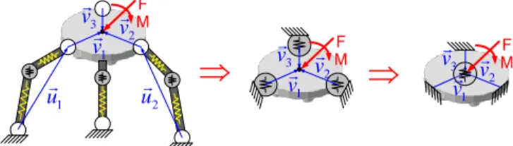
1 u u2 1 v v2 3 v MF F M MF
1 v v2 3 v 1 v v2 3 vFig. 1. Transformation of VJM models of typical parallel manipulator
C·( 0)
F K t t (6)
where the total Cartesian stiffness matrix KC is computed
using the chain aggregation formula
T 1 ( ) ( ) ( ) С С 1 m i i i v v i
K J K J (7)which integrates the Cartesian stiffness matrices ( ) С
i
K of all
m chains taking into account the difference between the
ref-erence point of the end-platform and the end-points of the chains (where the chains are connected to the mobile plat-form, Fig. 1). The latter is expressed via the Jacobians ( )i
v J 3 ( ) 1 3 6 6 ( i ) i v I v J 0 I (8)
where I3 is 33 identity matrix, (v) is a skew-symmetric
matrix corresponding to the vector v, vector vi defines dis-tance from the leg end-point to the end-effector reference point (see Fig.1).
Further, linear relations between the end-platform dis-placement tt0 and variations δqi,δθi in the joint coordi-nates of the chains may be presented as
1 1 ( ) C q 0 C θ ( ( ) ( ) 0 ) ( ); · ( ) δ i i · δ i · i · v v i i K J tt K J tt q θ (9)
where, the joint sensitivity matrices C q( ) C( ) θ ,
i i
K K are computed
from (4) and (5) assuming that F 0 and by neglecting all Hessians (here, the matrices C q( ) C( )
θ ,
i i
K K are expressed with
respect to the chain end-points).
B. Stiffness model aggregation for non-perfect chains
If the kinematic chains are non-perfect, the corresponding force-deflection relation (1) is shifted with respect to the point t0, i.e. fi(t0|t0)0. So, the manipulator assembling
in this point requires application of some non-zero forces Fi that generally do not compensate each other. Corresponding-ly, the end-platform location differs from t0 if the external
force applied to the end-platform is equal to zero. Let us de-note this difference as t and revise the above matrix equa-tions (6)-(9) assuming that, without the external loading, the chain end-point is shifted by εi with respect to t0 (it can be
also expressed as fi(t0εi|t0)0).
Using these notations, the desired stiffness model can be described by the following expressions
1 Δp 2 Δp 3 Δp 1 v 3 v 2 v 1 v v2 3 v Δp (1) p ε (2) p ε (3) p ε 1 Δp (2) p ε 3 Δp (1) p ε (3) p ε
(a) platform before assembling (b) platform after assembling
1 A 1 A 1 B 1 A 1 A 1 A 1 BO O O O 3 A 3 A 3 A 3 A 3 B 2 B 2 B 3 B 2 A 3 A 2 A 2 A 2 A 2 A 2 Δp
Fig. 2 Transformation of characteristic points of serial chains in assembling
of non-perfect parallel manipulator; (Ai,Ai - end-point locations of serial
chain before assembling for perfect and non-perfect manipulators respec-tively, Ai - end-point location of serial chain after assembling for
non-perfect manipulator) C·( 0 ) F K t t t (10) and 1 1 ( ) C q 0 C θ ( ( ) ( ) 0 ) ( ); δ ( ) · · δ · · i i v i i i i i v i K q J t t K J t t θ t t (11)
where the vectors t , ti should be computed using the assumptions presented above.
To find these additional parameters of the stiffness model, let us apply the energy based approach which allows us to express the potential energy of the parallel manipulator as
T ( )
C 1 · · 1 ( ) 2 i i i m i E t
ε t K ε t (12)where t ( p,φ) is displacement (position and orienta-tion) of the reference point, ( )
C i
K is the Cartesian stiffness matrix of the ith chain, and εi is the vector that integrates influence of all geometrical errors at the reference point.
It is obvious that after assembling, the considered mechan-ical system will occupy the most advantageous configuration with respect to the potential energy. It means that the desired vector t can be found from the expression E/ t 0, which allows us to evaluate the end-platform deflection
1 1 ( 1 ( ) ) C · C· m m i i i i i
t K K ε (13)and the end-platform location after assembling 0
t t t. Hence, for each separate kinematic chain, the end-frame def-lections Δ ti tεi due to assembling is expressed as
1 1 ) C 1 ( ) ( C · · m m i i i i i i i
Δ t K K ε ε (14)and the corresponding loading applied to the end-point (due to interaction with other non-perfect chains) is ( )
C·
i
i i
F K Δ t . Accordingly, the loadings in the virtual joints T
θ θ ( ) ( ) · i i i τ J F can be computed as
T ( ) θ θ ( ) C ) ( · ·Δ i i i i τ J K t (15)
It is worth mentioning that here
1 i
m i
F 0, since there isno external loading applied to the platform reference point after the assembling. Besides, it is possible to compute rele-vant deflections of the virtual and passive joint coordinates of the chains caused by the assembling
( ) ( )
C θ· ; C q·
i i
i i i i
θ K Δt q K Δt (16)
Thus, the above expressions allow us to evaluate the end-platform deflection and internal forces/torques caused by as-sembling of kinematic chains with geometrical errors. How-ever, the total manipulator Cartesian stiffness matrix KC is
the same as in Section III.A, since the geometrical errors are assumed to be small enough.
IV. STIFFNESS MODELS AGGREGATION FOR HIGH LOADING
If the external loading is rather high, the manipulator stiff-ness model is essentially non-linear and the above presented techniques cannot be applied directly. However, some basic ideas from Section III can also be adopted here.
A. Stiffness model of parallel manipulator
Let us focus first on the aggregation of stiffness models of separate serial chains into the stiffness model of the whole parallel manipulator in the loaded mode. To solve this prob-lem, it is necessary to obtain the non-linear force-deflection relation, which takes into account elastostatic properties of all kinematic chains, and to compute corresponding Carte-sian stiffness matrix.
Let us assume that, for the perfect kinematic chains, their end-points may be aligned and matched in the same target point t0, which corresponds to the desired end-platform
lo-cation. This point is assumed to be known and allows us to compute (from the inverse kinematic model) the actuator and passive joint coordinates defining nominal configurations of the chains (q0i,θ0i). It is also assumed that the stiffness models of all kinematic chains have been already obtained using techniques proposed in Sections II and are presented in
the form of non-linear force-deflection relations
0
( | )
i fi
F t t corresponding to the target point t0.
It is evident that the external loading F changes the end-platform location t0, hence it is reasonable to consider the
set of locations t in the neighborhood of target one. Under the above assumptions, for any given point t (from neigh-borhood of t0), it is possible to compute both the forces Fi and corresponding equilibrium configurations (qi,θi). Then,
in accordance with the superposition principle, the desired non-linear force-deflection relation for the whole parallel manipulator can be found by straightforward summation of all partial forces Fi, i.e.
0
1 | i m i f
t t F (17)where F denotes the total external loading applied to the end-platform. Corresponding curves can be obtained by mul-tiple repetition of the above described procedures for differ-ent values of the end-platform location t.
Furthermore, for each given t, the stiffness matrices ( ) C
i
K
of all kinematic chains can be computed using expression (3) So, the Cartesian stiffness matrix KC of the whole parallel
manipulator is the sum
( ) C C 1 m i i
K K (18)However, the matrices ( ) C q i
K and )
C θ ( i
K defining the "sensitivi-ty" of the chain joint coordinates (qi,θi) to the end-platform displacement cannot be aggregated in this way. They should be computed separately to evaluate forces/torques in the
joints/links T θ θ ( ) ( ) · i i i τ J F, where ) θ ( i J is Jacobian matrix of i-th kinematic chain wii-th respect to virtual joint coordinates (see equations (4) and (5)).
It is worth mentioning that it was implicitly assumed above that the manipulator assembling is equivalent to the aligning and matching of the chain end-frames. To deal with a more general case, when the chains are connected to the different points of the platform, it is necessary to slightly modify the chain geometrical models and to re-compute the forces/torques and the stiffness matrices by adding a virtual rigid link connecting the end-point of the chain and the ref-erence point of the platform. After relevant transformations, the presented technique above can be applied straightfor-wardly, using equations (7) and (9).
Besides, in contrast to Section III, here there are no evi-dent differences in stiffness models aggregation of perfect and non-perfect kinematic chains. In the last case, the chain geometrical errors εi are implicitly included in the force-deflection relations Fi fi( |t t0) in such a way that
0 0
( | )
i i
f t ε t 0. As a result, the end-platform cannot be located in the target point t0 without external loading, i.e.
0 0
1 |
m
i fi
t t 0. Moreover, without external loading, theend-platform location tε differs from the target one t0 by
the vector t that can be computed as
0
1 0 arg | m i i f
t t t t 0 (19)Relevant numerical routines is presented below.
Corresponding internal forces Fi defining the chain inter-nal loadings due to the geometrical errors can be computed by simple substitution t0t to the partial force deflection
relations Fi fi(t0 t|t0) . It is obvious that the sum of the Fi is equal to zero but they produce forces/torques in the links and joints if the parallel manipulator is over-constrained.
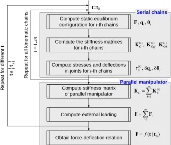
Hence, the developed aggregation technique allows us to obtain the non-linear force-deflection relation for a parallel manipulator in the loaded mode as well as to compute
Carte-sian stiffness matrices for any given target point t0 and
giv-en set of the giv-end-point locations { }t . This technique is sum-marized in Fig. 3. R e p e a t fo r d if fe re n t t
Compute static equilibrium configuration for i-th chains
Compute the stiffness matrices for i-th chains
, , i i i F q θ 1 m i i F F ( ) 1 m i C C i
K K ( ) ( ) Cθ ( ) Cq , , i i i C K K K 0 ( | ) f F t tCompute stresses and deflections in joints for i-th chains
) θ (i, δ , δ i i τ q θ Serial chains Parallel manipulator
Compute external loading
R e p e a t fo r a ll k in e m a ti c c h a in s t=t0
Obtain force-deflection relation
j tt 1.. im Compute stiffness matrix of parallel manipulator
Fig. 3 Aggregation of serial chains stiffness models technique
B. Compliance model of parallel manipulator
The non-linear force-deflection relation (17) allows us to evaluate the external force/torque F required to locate the manipulator at any given point t (assuming that the actuated coordinates are computed for the end-platform location t0
corresponding to the unloaded configuration). However in practice, it is often necessary to determine the end platform resistance to the external loading, i.e. to compute the deflec-tion caused by the force F applied to the end-platform. The desired value can be found from the non-linear compliance model that in a general case is expressed as
1 0 ( | ) f t F t (20)
and is defined by the inverse function 1 (...)
f which for
pa-rallel manipulators usually exists (due to the over-constrained structure). In contrast, for serial chains with pas-sive joints, the function 1
(...)
f cannot be computed since the corresponding Cartesian stiffness matrix ( )
C i
K is singular. It is obvious that in a general case, the function 1
(...)
f
cannot be expressed analytically. Hence, a dedicated itera-tive procedure, which is able to solve the non-linear equation (17) for t (assuming that F is given) is required. It is pro-posed here to apply a modification of Newton-Raphson technique which iteratively updates the desired value t in accordance with the expression
C 0 0 1 | f | t t K t t F t t (21)where t corresponds to the next iteration, KC
t t| 0
is the Cartesian stiffness matrix computed in the point t, and t0denotes the unloaded location of the end-platform. For this
iterative scheme, t0 can be also used as the initial value of
t. Similar to previous sub-section, within each iterative loop, corresponding configurations (qi,θi), the loadings Fi and stiffness matrices ( )
C i
K for each kinematic chain are computed using equations (2), and (3) respectively,
As follows from the relevant study, convergence of this iterative procedure is good enough if the function f(...) is smooth and non-singular in the neighborhood of t0. If it is
required to improve convergence, it is possible to modify the force F from iteration to iteration in accordance with the expression F ·F , where a scalar variable is monoton-ically increasing from 0 up to 1. The stopping criterion can be expressed in a straightforward way as F f
t t| 0
εF, where εF is the desired accuracy. A more detailedpresenta-tion of the developed iterative routines is given in Fig. 4 .
R e p e a t fo r d if fe re n t F | 0 εF f t t F 0 C 0 | | f t t K t t 1 0 ( | ) f t F t Aggregation of serial chains stiffness models
Obtain deflection-force relation
j
FF
Compute new location of end-platform No Yes t N e x t it e ra ti o n 0 , F 0 t t Stopping criterion is satisfied?
Fig. 4 Procedure for obtaining deflection-force relation for loaded parallel
manipulator
C. Compliance error compensation technique
To compensate for this undeterred end-platform displace-ment, the target point should be modified in such a way that, under the loading F, the end-platform is located in the de-sired point t0. This requirement can be expressed using the
stiffness model in the following way
(F)
0| 0 f F t t (22) where (F ) 0t denotes the modified target location. Hence, the problem is reduced to the solution of the nonlinear equation (22) for (F )
0
t , while F and t0 are assumed to be given. It is
worth mentioning that this equation completely differs from the equation F f( |t t0), where the unknown variable is t.
It means that here the compliance model does not allow us to compute the modified target point (F )
0
t straightforwardly, while the linear compensation technique directly operates with Cartesian compliance matrix.
To solve equation (22) for (F ) 0
t , a similar numerical tech-nique can be applied. It yields the following iterative scheme
(F) (F) 1 (F) 0 0 · 0 f ( | 0 ) t t t F t (23)where the prime corresponds to the next iteration, (0,1)
In the case where it is required to compensate for two types of errors (caused by the external loading F and inac-curacy in the serial chains), the second source of errors can be taken into account by changing of target location Δ t0 i for
each kinematic chain Δ t0i Δ t0 t εi, where t is the
end-platform deflections due to assembling of non-perfect kinematic chains and εi is shifting of the end-point location of ith kinematic chain because of geometrical errors. More detailed presentation of the developed iterative routines is given in Fig, 5 . F t ) F ( 1 0 | ε f F t t
Compute end-platform location
No Yes 1 (F) 0 | f F t F t N e x t it e ra ti o n 0 j ; ( )j t t F 0 F F t Obtain trajectory t
tj F t j
R e p e a t fo r d if fe re n t t0 0 j tt Stopping criterion is satisfied? (F) (F) 0 0 0 F t t t t 0 (F) 0 t tCompute corresponding equilibrium configuration and stiffness matrix
0i 0 i Δt Δt t ε R e p e a t fo r a ll k in e m a ti c c h a in s 1.. im
Compute end-point location for the ith chain
( ) C , , , i i i i q θ F K
Fig. 5 Procedure for compensation of compliance errors in parallel
manipu-lator
Hence, using the proposed computational techniques, it is possible to compensate for the main part compliance errors by properly adjusting the reference trajectory that is used as an input for the robotic controller.
V. APPLICATIONEXAMPLES
A. Aggregation non-perfect serial chains without loading
Let us illustrate the developed stiffness model aggregation technique by examples that deal with assembling of Orthog-lide parallel translational manipulators with geometrical er-rors in kinematic chains (Fig. 6) [23]. Let us assume that the manipulators have geometrical errors in the kinematic chains, which have effects on the end-point location and pro-voke internal loadings in the joints.
Taking into account the shape of the manipulator work-space, let us focus on the stiffness analysis of these manipu-lators in five characteristic points: isotropic point Q0, two limit points Q1 and Q2. with symmetrical configuration and two limit points Q3 and Q4. with non-symmetrical configura-tion [6][7]. Let us estimate the end-effector locaconfigura-tion and in-ternal deflections/loadings caused by the geometrical errors in the chains. The stiffness matrices of the chains in the points Q0...Q4 have been computed using the technique pro-posed in Section III.A.
For illustration purposes, let us investigate two types of
geometrical errors
Case A: Each actuator of the manipulator has a position
error 1 mm in actuator location;
Case B: Each actuator of the manipulator has an angular
error 1° in actuator location.
In case A, as it follows from the chains geometry, the deflec-tions of the chain end-points before assembling are 0
i i
ε ε . In case B, the values εi were computed using the geometric-al model with non-perfect chains:
(a) Photo Q1 Q2 Q0 Q3 Q4 (b) CAD-model
Fig. 6 Photo and CAD models of Orthoglide manipulator
Further, substituting deflections εi and corresponding chain stiffness matrices ( )
C i
K into formulas (13) - (16), were
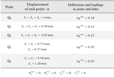
computed the assembling-induced values of the end-platform displacement, the internal forces/torques and the relevant displacements in virtual and passive joints. The main results
of this study are summarized in Tables 1–2, where m ax
q
is the maximum rotational displacement of passive joints,
m ax m ax
p , φ
are maximum displacement of translational and
rotational virtual springs respectively, m ax m ax
p , φ
are
maxi-mum torques in translational and rotational virtual joints re-spectively, m ax
M is the maximum moment in the chains, caused by assembling of a parallel manipulator with the non-perfect kinematic chains.
These results show that in the Case A (Table 1), the geo-metrical errors in the kinematic chains do not cause any in-ternal loading. However, they provoke the shift of the end-platform location up to 2.02 mm (point Q2). Corresponding
changes in passive joint coordinates are about 0.42̊
(point Q2)
In contrast, in the Case B, the geometrical errors in the ki-nematic chains of Orthoglide (Table 2) cause essential inter-nal loadings. For instance, in point Q1 the torque applied to the end-point of the chain can reach up to 8.91 N ·m. This loading induces displacements up to 0.41 m m and 0.62 for translational and rotational virtual springs respectively. It should be noted that the loadings for rotational virtual springs are up to 11.96 N ·m, but for translational virtual springs they are equal to zero (in spite of non-zero deflec-tions in them). Nevertheless, this result is reasonable due to the non-diagonal structure of the matrices ( )
C i
K representing
couplings between rotational and translational deflections. Variations in the passive joint coordinates can reach up to
0.67 (Point Q3). For the end-platform, this case study gives the positional deflection up to 1.31 mm (Point Q3) and the
rotational deflection up to 0.62 (Point Q1). It is obvious that the total sum of all internal loadings is equal to zero
Table 1. Assembling of Orthoglide manipulator with non-perfect chains:
loadings and displacements for the Case A ( 1, 2, 3, 0, 0, 0
T
t ,
1
F 0, F20, F30)
Point of end-point Displacement t
Deflections and loadings in joints and links Q0 1231 m m ; max 0.18 q Q1 1230.50 m m max 0.14 q Q2 1232.02 m m ; max 0.42 q Q3 1 2 3 0.73 m m ; m m 0.27 max 0.20 q Q4 1 2 3 0.56 m m ; m m 1.28 max 0.26 q m ax m ax m ax m ax p 0; φ 0; p 0; φ 0
Table 2. Assembling of Orthoglide manipulator with non-perfect chains:
loadings and displacements for the case B ( 1, 2, 3, 1, 2, 3
T
t ,
1
F 0, F20, F30)
Point of end-point Displacement t
Deflections and loadings in joints and links
Q0 1 2 3 1 2 3 0 m m ; 0. 3 ;0 m ax m ax m ax m ax p φ m ax m ax p φ ·m ; 0 .3 1 0 .0 5 m 2 .0 9 N m ; 0 .9 4 0; 2 .0 9 N ·m M q Q1 1 2 3 1 2 3 0.41 m m . ; ; 0 62 m ax m ax m ax m ax p φ m ax m ax p φ ·m ; 0 .6 3 0 .5 4 m m 8 .9 1 ; 1 .7 4 0 N ; 1 1 .9 6 N ·m M q Q2 1 2 3 1 2 3 0.96 m m ; .21 ; 0 m ax m ax m ax m ax p φ m ax m ax p φ ·m ; 0 .5 2 0 .1 4 m 1 .4 8 N m ; 0 .8 0 0; 1 .7 5 N ·m M q Q3 1 1 2 2 3 3 0.91 m m ; 0.19 1.31 m m ; 0.49 0.58 m m ; 0.44 m ax m ax m ax m ax p φ m ax m ax p φ ·m ; 0 .6 7 0 .9 9 m 4 .3 3 N m ; 1 .4 9 0; 4 8 4. N·m M q Q4 1 1 2 2 3 3 0.93 m m ; 0.33 0.10 m m ; 0.22 0.25 m m ; 0.31 m ax m ax m ax m ax p φ m ax m ax p φ ·m ; 0 .5 9 0 .6 2 m 2 .9 8 N m ; 1 .3 0 0; 4 .0 N ·m M q
B. Aggregation non-perfect serial chains under loading
Now let us consider the chain stiffness model aggregation of Orthoglide manipulator under external loading caused by groove milling.. According to [24], such technological
process causes forces Fr 2 1 5N ; Ft 1 0N ;
2 5
z
F N . The tool length h1 0 0m m leads to torques at
the manipulator end-effector Mx,1N·mand
, 21.5 ·
y m
M N . It is assumed that the manipulator has two sources of inaccuracy:
(i) the assembling errors in the kinematic chains causing internal forces and relevant deflections in joints and links due to manipulator over-constrained structure; (ii) the external loading F 217 N caused by the
cut-ting force, which generates essential compliance def-lections causing non-desirable end-platform dis-placement.
Similar to the previous example, it is assumed that the first source of inaccuracy can be caused by translational (Case A) and rotational (Case B) errors in the actuator locations.
Let us consider the case study when Orthoglide performs milling from the point Q2 to Q5(-73.65, 126.35, -73.65) fol-lowing the straight line. Simulation results for two error sources for the Case A and Case B are presented in Fig 7 and Fig. 8 respectively. They include the target trajectories, dis-placements caused by the cutting forces and non-perfect geometry as well as total compliance errors and the dis-placement evaluated using the superposition principle. The results are presented for the displacements in x- and z-directions. -50 0 50 100 -0.5 0 0.5 1 1.5 2 2.5 -50 0 50 100 -0.5 0 0.5 1 1.5 2 2.5 , [ ] y mm , [ ] y mm 0, [ ] zz mm 0, [ ] xx mm
(a) Errors in x-direction (a) Errors in z-direction
2 3 1 5 4 2 3 1 5 4
Fig. 7. Case A: Displacements caused different sources of inaccuracy
dur-ing milldur-ing along the straight line from point Q2 to Q4 using Orthoglide
manipulator: (1) target trajectory, (2) displacements caused by cutting forces, (3) displacements caused by non-perfect geometry, (4) total compli-ance error, (5) displacements obtained using superposition principle.
-50 0 50 100 -1 -0.5 0 0.5 1 -50 0 50 100 -1 -0.5 0 0.5 , [ ] y mm , [ ] y mm 0, [ ] zz mm 0, [ ] xx mm
(a) Errors in x-direction (a) Errors in z-direction
2 3 1 5 4 2 3 1 5 4
Fig. 8. Case B: Displacements caused different sources of inaccuracy
dur-ing milldur-ing along the straight line from point Q2 to Q4 using Orthoglide
manipulator: (1) target trajectory, (2) displacements caused by cutting forces, (3) displacements caused by non-perfect geometry, (4) total compli-ance error, (5) displacements obtained using superposition principle.
The obtained results show that, due to the cutting force, the end-platform displacement in the x-direction with respect to the target trajectory may reach up to 0.4 mm and its varia-tions are insignificant (compared to the errors caused by in-accuracy in the serial chains). In particular, in Case A, the errors in the x-direction induced by cutting forces and inac-curacy in serial chains have the same direction, and, conse-quently total error is close to 2.5 mm in the point Q2 and
about 0.8 mm in the vicinity of the point Q4. In contrast, in the Case B, the compliance errors in the x-direction induced by the cutting forces and inaccuracy in the serial chains have different signs, so the total error in the loaded mode is less than in the unloaded one. This error varies from -0.6 mm to 0.1 mm along the trajectory and even reduced to zero when the y-coordinate is about 80 mm. In the z-direction, the er-rors caused by the assembling of non-perfect serial chains is much higher (from 0.5 mm to 2.1 mm for the Case A and from -1 mm to 1 mm in the Case B). To compensate for these errors the technique presented in sub-section IV.C can be applied.
VI. CONCLUSIONS
This paper presents the non-linear stiffness modeling technique for parallel manipulators composed of non-perfect serial chains, whose geometry differ from the nominal one and where essential internal forces/torques are generated. This technique is based on the developed aggregation proce-dure that combines the chain stiffness models and produces the relevant force-deflection relation, the aggregated Carte-sian stiffness matrix and also allows us to evaluate changes in the reference point location caused by inaccuracy in kine-matic chains. In addition, expressions for computing of the internal deflections and forces/torques in joints are proposed. The developed technique can be applied to both over-constrained and under-over-constrained manipulators, and is suit-able for the cases of both small and large deflections.
The advantages of the developed technique are illustrated by an example that deals with the over-constrained parallel manipulator of the Orthoglide architecture. It demonstrates the technique ability to evaluate the end-effector deflections caused by conventional sources (cutting forces/torques ap-plied to the end-effector that arise while workpiece processing) and also induced by inaccuracy in serial chains of the parallel manipulator. Relevant plots that illustrate in-fluence of different error sources on the manipulator position accuracy are presented.
In future, the proposed technique will be integrated in a software toolbox that can be used for parallel manipulators of complex architecture and applied to the industrial problem of the compliance error compensation in robotic machining cells.
ACKNOWLEDGEMENTS
The work presented in this paper was partially funded by the Region “Pays de la Loire” (France), and by the ANR, France (project COROUSSO).
REFERENCES
[1] O. Company, S. Krut, F. Pierrot, Modelling and preliminary design issues of a 4-axis parallel machine for heavy parts handling, Journal of Multibody Dynamics 216 (2002) 1–11.
[2] J. Kövecses, J. Angeles, The stiffness matrix in elastically articulated rigid-body systems, Multibody System Dynamics 18(2) (2007) 169– 184.
[3] T. Bonnemains, H. Chanel, C. Bouzgarrou and P. Ray, Definition of a new static model of parallel kinematic machines: highlighting of overconstraint influence, in: Proceedings of IEEE Int. Conference on Intelligent Robots and Systems (IROS), 2008, pp. 2416–2421. [4] D. Deblaise, X. Hernot, P.Maurine, A systematic analytical method
for PKM stiffness matrix calculation, In: Proceedings of the IEEE In-ternational Conference on Robotics and Automation (ICRA), Orlan-do, Florida, 2006, pp. 4213-4219.
[5] Y. Li, Q. Xu, Stiffness analysis for a 3-PUU parallel kinematic ma-chine, Mechanism and Machine Theory 43(2) (2008) 186-200. [6] A. Pashkevich, D. Chablat, P. Wenger, Stiffness analysis of
overcon-strained parallel manipulators, Mechanism and Machine Theory 44 (2009) 966-982.
[7] A. Pashkevich, A. Klimchik, D. Chablat, "Enhanced stiffness model-ing of manipulators with passive joints", Mechanism and Machine Theory, vol. 46(5), pp. 662-679, 2011.
[8] A. Pashkevich, A. Klimchik, S. Caro, D. Chablat, Cartesian stiffness matrix of manipulators with passive joints: analytical approach, In: IEEE/RSJ International Conference on Intelligent Robots and Systems (IROS 2011), September 25-30, 2011, USA, San Francisco, Califor-nia, pp. 4034-4041.
[9] J. Salisbury, Active Stiffness Control of a Manipulator in Cartesian Coordinates, in: 19th IEEE Conference on Decision and Control, 1980, pp. 87–97.
[10] C. Gosselin, Stiffness mapping for parallel manipulators, IEEE Trans-actions on Robotics and Automation 6(3) (1990) 377–382.
[11] S. Chen, I. Kao, Conservative Congruence Transformation for Joint and Cartesian Stiffness Matrices of Robotic Hands and Fingers, The International Journal of Robotics Research 19(9) (2000) 835–847 [12] C. Quennouelle, C. M. Gosselin, Stiffness Matrix of Compliant
Paral-lel Mechanisms, In: Springer Advances in Robot Kinematics: Analy-sis and Design, 2008, pp. 331-341.
[13] I. Tyapin, G. Hovland, Kinematic and elastostatic design optimization of the 3-DOF Gantry-Tau parallel kinamatic manipulator,Modelling, Identification and Control, 30(2) (2009) 39-56
[14] G. Alici, B. Shirinzadeh, Enhanced stiffness modeling, identification and characterization for robot manipulators, Proceedings of IEEE Transactions on Robotics 21(4) (2005) 554–564.
[15] A. Pashkevich, A. Klimchik, D. Chablat, Ph. Wenger, Accuracy Im-provement for Stiffness Modeling of Parallel Manipulators, In: Pro-ceedings of 42nd CIRP Conference on Manufacturing Systems, Gre-noble, France, 2009.
[16] J.-P. Merlet, Parallel Robots, Kluwer Academic Publishers, Dor-drecht, 2006.
[17] D. Zhang, F. Xi, C.M. Mechefske, S.Y.T. Lang, Analysis of parallel kinematic machine with kinetostatic modeling method, Robotics and Computer-Integrated Manufacturing 20 (2) (2004) 151–165 [18] D. Chakarov, "Study of antagonistic stiffness of parallel manipulators
with actuation redundancy," Mechanism and Machine Theory. Vol. 39(6), pp. 583–601, 2004.
[19] B.-J. Yi, R.A. Freeman, "Geometric analysis antagonistic stiffness redundantly actuated parallel mechanism," Journal of Robotic Sys-tems 10(5) (1993) 581-603.
[20] F. Xi, D. Zhang, Ch. M. Mechefske, Sh. Y. T. Lang, "Global kinetos-tatic modelling of tripod-based parallel kinematic machine," Mechan-ism and Machine Theory 39 (4), pp. 357–377, 2004.
[21] R. Rizk, N. Andreff, J.C. Fauroux, J.M. Lavest and G. Gogu, Preci-sion Study of a Decoupled Four Degrees of Freedom Parallel Robot Including Manufacturing and Assembling Errors, Advances in Inte-grated Design and Manufacturing in Mechanical, S. Tichkiewitch et al. (eds.), Springer 2007, Engineering II, 111–127.
[22] W. Wei, N. Simaan, "Design of planar parallel robots with preloaded flexures for guaranteed backlash prevention," ASME Journal of Me-chanisms and Robotics, Vol. 2(1) , 10 pages, 2010
[23] D. Chablat, P. Wenger, Architecture Optimization of a 3-DOF Parallel Mechanism for Machining Applications, the Orthoglide, IEEE Trans-actions On Robotics and Automation 19(3) (2003) 403-410. [24] F. Majou, C. Gosselin, P. Wenger, D. Chablat, Parametric stiffness
analysis of the Orthoglide, Mechanism and Machine Theory 42 (2007) 296-311.