HAL Id: hal-01007974
https://hal.archives-ouvertes.fr/hal-01007974
Submitted on 29 Oct 2018
HAL is a multi-disciplinary open access
archive for the deposit and dissemination of sci-entific research documents, whether they are pub-lished or not. The documents may come from teaching and research institutions in France or abroad, or from public or private research centers.
L’archive ouverte pluridisciplinaire HAL, est destinée au dépôt et à la diffusion de documents scientifiques de niveau recherche, publiés ou non, émanant des établissements d’enseignement et de recherche français ou étrangers, des laboratoires publics ou privés.
Characterisation of novel K-Cor sandwich structures
Pascal Casari, Denis Cartié, Peter Davies
To cite this version:
Pascal Casari, Denis Cartié, Peter Davies. Characterisation of novel K-Cor sandwich structures. Sandwich Structures 7: Advancing with Sandwich Structures and Materials, Aug 2005, Aalborg, Denmark. �10.1007/1-4020-3848-8_87�. �hal-01007974�
CHARACTERISATION OF NOVEL K-COR
SANDWICH STRUCTURES
Pascal Casari1, Denis Cartié2and Peter Davies3 1
GeM, Institut de Recherche en Génie Civil et Mécanique, UMR CNRS 6183, BP 92208, 44322 Nantes Cedex 3, France
2
Advanced Materials Department, School of Indu
2
strial and Manufacturing Science, Cranfield u
University, Cranfield MK43 0AL, UK
3
Materials and Structures Group, Ifremer Brest Centre, 29280 Plouzané, France
Abstract Sandwich beams reinforced with K-Cor™ are characterized in terms of
stiffness, strength and fracture by means of static tests, and compared to traditional sandwich materials. Stiffness is evaluated with a series of three flexure tests applied to each sample. Strength tests show different failure mechanisms for the two architectures. Mode I fracture properties are measured and a significant increase in the core toughness of reinforced samples is revealed.
Keywords: K-Cor™, pin reinforced foam cores, fracture, damage tolerance.
1.
INTRODUCTION
Polymer foam core sandwich construction is becoming more popular for cost and weight efficiency reasons. However, the lack of mechanical properties can sometimes be a problem. The present paper considers a solution where the polymer foam is locally reinforced by rigid carbon fibre rods. This ‘pin’ reinforcement technology has been developed recently1 and
is known under the commercial name of X-Cor™ and K-Cor™.
X-Cor™ and K-Cor™ sandwich panels are structures composed of skins separated with a polymeric foam in which cured carbon fibre rods have been
inserted in a pre-determined truss configuration. During the manufacturing process, the pins extend beyond each foam surface. For the X-Cor™ panels, uncured face sheets are pressed on each side of the core. During cure, the pins enter the face sheets. The K-Cor™ construction varies by the fact that the length of pins which extends outside the polymeric foam core is pressed flat on the surface of the foam by a hot-press process. The skins (of any material) are then adhesively bonded onto the surface of the core. For both type of cores, the truss transfers some of the through-thickness and shear loads, and enhances the properties of the core [1-3].
Due to the fact that there is no need for an adhesive film in the X-cor™ configuration, the aerospace industry developed this configuration to replace Nomex® honeycomb cores in weight saving exercises. The truss was designed to reproduce the general mechanical properties of the cores already in use. For a specific application, (Sikorsky Comanche access doors) a weight saving of 10 to 15% was achieved by using X-cor™ as opposed to Nomex honeycomb [4]. The transition between solid laminates and X-cor™ truss has been studied by O’Brien et al. [5]. They showed that the failure modes are very specific to the loading conditions applied locally on the truss. Because of the different mechanical links between the pins and the skins in K-cor™, there is no knowledge of the failure modes in the solid laminate to sandwich transition area.
2.
MANUFACTURING
The sandwich panels were constructed with woven carbon fibre face sheets and Rohacell® polymethacrymalimide foam core. Some of the foam cores were reinforced by pultruded carbon fibre / epoxy rods, creating a 2 dimensional truss. The details are as follows.
Two 290mm x 210mm x 12mm blocks of Rohacell® 51IG (density 51kg/m3) were chamfered along two edges, creating the ramps. One foam
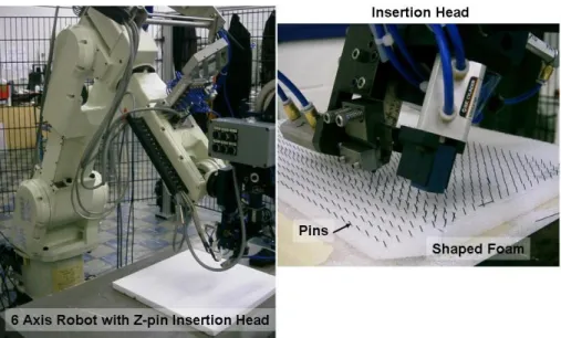
block was reinforced by 0.5mm diameter pultruded T650 carbon fibre / epoxy rods. The rods were inserted using a 6-Axis Kawasaki robot arm (see Figure 1). The pins were inserted in two directions at nominal angles of ±22°, creating a truss in the direction 1-3 of the samples (see Figure 2.). The pin truss extended beyond each surface of the laminate for a free length of approximately 3mm. The pins were folded back, flush with the foam surface using a hot press process. The beams have been specifically designed to study the stress transfer in the transition area between sandwich and solid laminates. The skins are relatively thick in order to study a design of sandwich structure commonly used in the marine industry.
Figure 1. 6-Axis Robot in use at Cranfield University and Close Up on the Insertion head.
Figure 2. Specimen Geometry.
The face sheets were constructed using 8 plies of 977-6 resin / IM7 woven carbon fibre pre-preg. An AF163-2 adhesive film was used between the foam core and the surface plies. The 8 plies of the top face sheet were laid up and debulked every ply under vacuum to assure good shape conformity with the core. The panels were cured in an autoclave at 135°C at a pressure of 0.2 MPa (2 bars) for 3 hours.
40 mm wide samples were cut using a diamond coated circular saw. The nominal geometry of the samples is given in Figure 2.
3.
STIFFNESS
For evaluating the effect of pins on the stiffness, a set of three flexure tests is applied to each sample. This ensures that the beams are loaded with
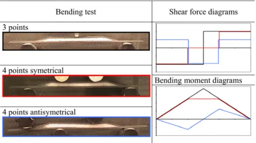
various bending moments and shear forces and allows a more accurate characterization of shear stiffnesses. The three tests are shown in (Table 1) :
x Three point bending. The bending moment is maximum in the center whereas the shear force alternates from a constant positive value on one side of the loading point to an opposite one on the other side. x Four point bending test. The aim of this test is to ensure a central part
with no shear force and a constant bending moment
x Four point bending test with an asymmetric arrangement. This produces a bending moment diagram with a zero value in the centre, and a shear force which is maximum at this point.
Table 1. Tests and corresponding internal loads on the sandwich samples.
Each test has been conducted on 3 samples from classical and reinforced sandwich beams. The samples have been loaded between 0.5 and 1.5 kN in order to produce a deflection around 1 mm. Table 2 directly reports the bending stiffness results. Obviously, the stiffness of samples reinforced with K-Cor™ is much higher than the classical sandwich value.
Material Sample 3 points 4 pts symmetrical 4 pts antisymmetrical 1 0.28 0.52 0.58 2 0.27 0.4 0.43 No pins 3 0.25 0.57 0.40 1 0.80 1.39 2.12 2 0.82 1.20 1.77 With pins 3 0.80 1.05 1.97
Table 2. Bending stiffness (kN/mm).
4.
FRACTURE
4.1
Damage development in flexure
Beam specimens with and without pins were loaded to failure in three point flexure. Two test configurations were used, with the loading on alternate facings of the beams. The same fixture as above was employed. The loading rate was 5mm/min.
4.1.1 Configuration 1
This is the more severe configuration as the joint between the sandwich and the beam end is subjected to both shear and tensile loads.
a)
b)
c)
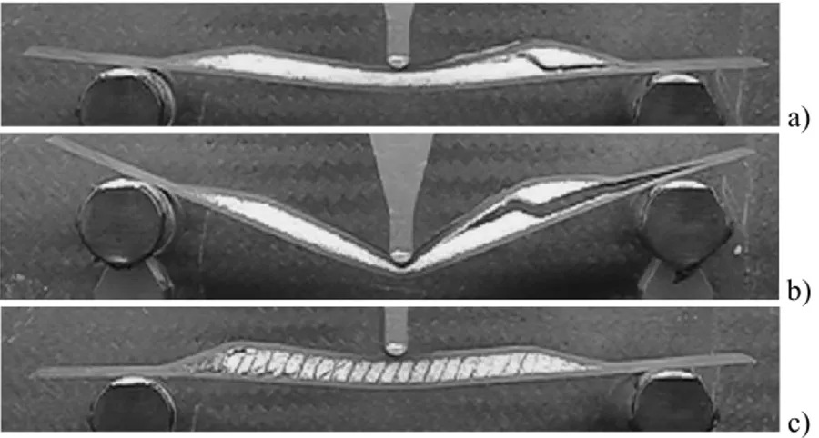
For the sandwich without pins the first damage appears at the end of the foam, Figure 3a, as a shear crack. Further loading results in compression failure below the upper load point, and continuing the test leads to core crushing and a final tensile failure in the lower facing, Figure 3b.
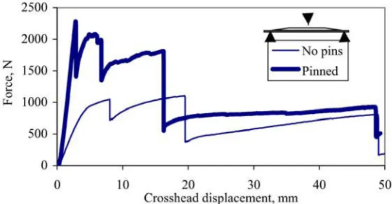
The inclusion of pins delays the appearance of first damage. Some cracks still appear in the core foam but the pins maintain the overall integrity of the sandwich up to compressive failure below the upper loading point, Figure Figure 3c. They also delay the crushing of the core so that final tensile failure in the lower facing appears later. The displacement-load curve shows these different steps after an initial linear part.
Figure 4. Load-displacement, configuration 1.
4.1.2 Configuration 2
Turning the specimen and loading from the other side results in compression rather than tension at the foam ends. Figure 5 shows examples of load-displacement plots. The loads are slightly higher for both materials.
Figure 5. Load-displacement, configuration 2.
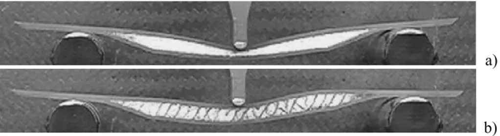
For the classical beam (Figure 6a) the failure mechanisms are mostly crushing of the core and indentation of the skin which lead to a yield point on the load-displacement curve following the elastic region. The beam reinforced with K-cor™ (Figure 6b) shows a part cracked in shear on the right side. This series of cracks corresponds to the first peak on the load-displacement curve.
a) b)
Figure 6. Failure mechanisms of sandwich beams in bending in configuration 2.
4.2
Crack propagation in the core
The inclusion of pins clearly has a beneficial effect on the flexural response of these sandwich structures. An additional benefit to be expected is improved damage tolerance. Extensive work on delamination of pinned laminates has clearly shown that pins play a major role in slowing crack propagation or even stopping it completely [6]. It is therefore of interest to examine the role of through-core pinning on crack behaviour in sandwich materials.
Some preliminary crack propagation tests have been performed using a Double Cantilever Beam (DCB) specimen, Figure 7. The starter crack was introduced at core mid-thickness with a saw, then sharpened by a razor blade. Notches in both specimens were the same length, 40 mm from the load point. Load was introduced by bonding aluminium blocks to the facings. Loading is initially mode I. In the foam without pins the crack propagated at mid-thickness in a symmetrical manner as shown in Figure 7. In the K-Cor™ specimen the starter crack did not propagate, a damage zone developed near the lower core/facing interface and propagated there as shown in Figure 7.
Figure 7. Two types of DCB specimen - sandwich and K-cor™.
Figure 8 shows examples of load-displacement plots. It is apparent that considerably higher energy is necessary to propagate a crack in the pinned foam. The approximate fracture energies (Gc) are 460 J/m² for the foam and
1690 J/m² for the K-Cor™, at least three times higher.
Figure 8. Load-displacement plots, DCB tests, corresponding to 55 mm crack
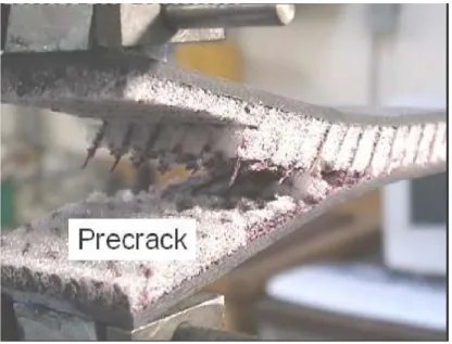
The through thickness pinning provides an effective barrier to crack propagation as shown in Figure 9. These pins must be pulled out or broken before the crack can advance.
Figure 9. K-Cor™ DCB specimen, details of crack initiation region.
It should be emphasized that these are preliminary results for one K-Cor™ configuration. An advantage of these materials is that the pinning parameters can be tailored for a particular application; optimization of pin material, density, angle and sandwich manufacturing conditions may result in further significant improvements in damage tolerance.
5.
CONCLUSION
This paper presents results from a preliminary study of the mechanical behaviour of a pin reinforced foam core sandwich material. Stiffness, fracture strength and damage tolerance have been examined, and it is apparent that for a similar weight all these properties can be significantly improved.
REFERENCES
1. Cartié D.D.R. and Fleck, N.A. “The effect of pin reinforcement upon the through-thickness compressive strength of foam cored sandwich panels”. Composites Science and Technology, Vol. 63, pp. 2401-2409, 2003.
2. Marasco A.I., Cartié D.D.R., Partridge I.K. and Rezai A., “Mechanical properties balance in novel Z-pinned sandwich panels: Out of plane properties”, Composites Part A, 2005, in press.
3. Partridge, I.K., Cartié, D.D.R. and Bonnington, T., Manufacture and performance of Z-pinned composites, Ch. 3 in Advanced Polymeric Materials: Structure-Property Relationships, Advani S., Shonaike G. (eds), CRC Press, April 2003, ISBN 1-58716-047-1.
4. Cartensen T. C, Kunkel E, Magee C. “X-cor advanced sandwich core material”. In: 33rd International SAMPE Technical Conference, Seattle, WA, November 2001.
5. O’Brien T. K, Paris I. L., “Exploratory investigation of failure mechanisms in transition regions between solid laminates and X-cor® truss sandwich”. Composite Structures, Vol 57, pp. 189-204, 2002.
6. Partridge I. K and Cartié D. D. R, “Delamination resistant laminates by Z-Fiber® pinning. Part I Manufacture and fracture performance”, Composites Part A: Applied Science and Manufacturing, Vol. 35, pp. 55-64, 2005.