HAL Id: hal-01114680
https://hal.archives-ouvertes.fr/hal-01114680
Submitted on 9 Feb 2015
HAL is a multi-disciplinary open access
archive for the deposit and dissemination of sci-entific research documents, whether they are pub-lished or not. The documents may come from teaching and research institutions in France or abroad, or from public or private research centers.
L’archive ouverte pluridisciplinaire HAL, est destinée au dépôt et à la diffusion de documents scientifiques de niveau recherche, publiés ou non, émanant des établissements d’enseignement et de recherche français ou étrangers, des laboratoires publics ou privés.
beam in one plane
Sébastien Clauzier, Stéphane Avrillon, Laurent Le Coq, Mohamed Himdi,
Franck Colombel, Erwan Rochefort
To cite this version:
Sébastien Clauzier, Stéphane Avrillon, Laurent Le Coq, Mohamed Himdi, Franck Colombel, et al.. Slotted waveguide antenna with a near-field focused beam in one plane. IET Microwaves Antennas and Propagation, Institution of Engineering and Technology, 2015, 9 (7), pp.634-639. �10.1049/iet-map.2014.0479�. �hal-01114680�
Slotted waveguide antenna with a near-field focused
beam in one plane
Sébastien Clauzier1,, Stéphane Avrillon2,, Laurent Le Coq2,, Mohamed Himdi2,, Franck Colombel2,, and Erwan Rochefort1
Email : sebclauzier@gmail.com, stephane.avrillon@univ-rennes1.fr, laurent.le-coq@univ-rennes1.fr, mohamed.himdi@univ-rennes1.fr, franck.colombel@univ-rennes1.fr, erochefort@cmn-cherbourg.com.
1CMN (Constructions Mécaniques de Normandie), 51, rue de la Bretonnière BP539, 50105 Cherbourg,
France
2IETR (Institut d’Electronique et de Télécommunications de Rennes) UMR-CNRS 6164, Campus de
Beaulieu, 263 avenue du Général Leclerc, 35042 Rennes, France
Abstract--- A slotted waveguide providing a two dimensional near-field focused beam is presented in this
paper. This antenna focuses the beam in the E-plane and provides a wide beam in the H-plane in order to illuminate a linear array, as reflect- or transmit-array antenna with a small width (100mm) and a very large length (1530mm) located in the near-field region. The simulated field distribution on the array is found to be in very good agreement with the measurement of a prototype at 9.41GHz.
Index Terms--- slotted waveguide antenna, near-field focusing technique
1. INTRODUCTION
The near-field focusing technique is used in several applications such as imagery sensing, characterization of materials or in biomedical devices. To focus a beam at a distance , called the focal distance, from the antenna, the phase has to be adjusted along the radiating aperture to obtain a locally plane wave-front (Gaussian beam property) in the desired spatial location. Today, many antennas allow focusing a beam in the near-field region: planar array [1], horn with a dielectric lens [2, 3] or rectangular slotted waveguide [4]. But all these antennas focus a beam in 3 dimensions (spot). In some cases, an antenna which focuses along one plane and provides a broad beam in the orthogonal plane (2 dimensional focused beam), can be
interesting, such as in optics for testing a long material with a small width and a long length or in microwave application for feeding a linear reflect- or transmit-array antenna.
In [5,6,7], the authors design two dimensional focusing antennas using leaky-wave principle considering a tapered microstrip line [5], a rectilinear slotted waveguide [6] or SIW (Substrate Integrated Waveguide) technology [7]. However, this three geometries use partly or completely a printed circuit technology. In our case, the focused antenna will be used as a feed for a transmit-array antenna in navigation radar technology. In such applications, the antenna has to accept high power with a good radiation efficiency, so we will favour a complete waveguide technology. In [8], a horn antenna with a biconvex dielectric lens inserted in its aperture has been investigated to provide a two dimensional focused beam. But the addition of the lens in the aperture of the H-plane sectoral horn reduces the beam width in the E-plane and the maximum ratio length/width of the beam at the focal point was equal to 8.
This paper presents a slotted waveguide antenna dedicated to the illumination of an array with a length of 1530mm and a width of 100mm (ratio length/width equals to 15.3), located in the near-field region of the feed. This structure focuses the field along one plane in order to illuminate the width of the array and provides a wide beam along the orthogonal plane to illuminate the length of the array. Therefore, the spot size specifications are determined by the dimensions of the illuminated array. As the whole system (array + feed) has been developed for a navigation radar embedded inside a compact integrated mast, the architectural restrictions enforce the focused beam characteristics. For example, applying the transmit-array technology to design the illuminated antenna, the standard beamwidth aperture of a navigation radar leads to a 96 elements linear array in the horizontal plane, which corresponds to a length of 1530mm.The restriction in the dimensions of the mast induces a maximum vertical size of the transmit-array antenna of 100mm, with a maximum distance of 500mm between the feed and the transmit-array antenna. To minimize the spill-over losses, the normalized field level at the edge of the array has to be closed to -10dB. So the focused antenna has to be designed to reach these spot sizes restrictions, which are summed up in table 1.
Table 1 : CHARACTERISTICS OF THE FOCUSED BEAM Characteristics Value Beamwidth at -10dB in the horizontal plane 1530mm
Beamwidth at -10dB in the vertical plane 100mm Maximum distance of the focal point 500mm
In this paper, we present a focused antenna which reaches these specifications with low losses and high power handling. This paper is organized as follows. In the first part, we carry out the theory of the near-field focusing technique with a slotted waveguide. In the second part, we present the results of the simulation with CST Microwave Studio. Finally, these theoretical results are compared with measurement.
2. DESIGNPROCESSOFTHENEAR-FIELDFOCUSINGSLOTTEDWAVEGUIDE
ANTENNA
2.1 Presentation of the near-field focusing technique
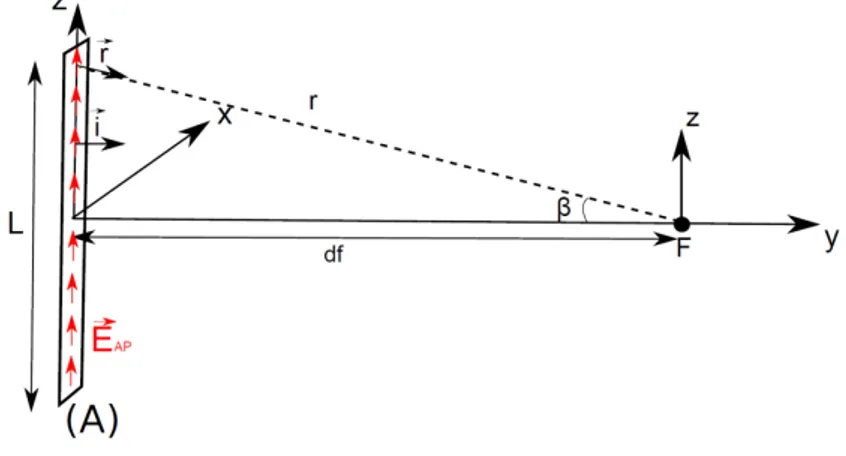
Let's consider a rectangular antenna aperture (A) of length L as shown in figure 1, with a field distribution over this aperture as expressed in equation (1):
With,
and respectively the magnitude and phase of the field distribution, and the coordinates of the aperture.
As seen in [8] and considering the reference plane at z=0, the phase distribution along the aperture needed to focus the beam at a distance must be equal to:
(2) (1)
Where,
is the free space constant.
Figure 1: Illustration of near-field focusing theory
Such a phase variation along the aperture can be obtained in different ways: a first solution consists in modifying the field distribution of horn antenna by inserting a dielectric lens inside its aperture as shown in [8]; a second solution uses the modification of the complex propagation wave number to obtain the require phase variation; another solution is based on the synthesis of such a variation thanks to discrete radiating sources. This second solution is proposed in the paper: a slotted waveguide antenna is designed, optimizing the slots and their positions on the waveguide to obtain the desired field distribution.
It is important to notice that the previous formulation (Equation (2)) uses the ray-tracing theory. Of course in the reactive near-field region, the electric-field behaviour is more complex and its computation needs much more efforts. But even if the theory presented in this paper is limited, it has the advantage to be very easy to implement and gives a good approximation of the waveguide design.
2.1 Design of the antenna
The shape of the slots has been chosen using [9]. The I-slot design (Figure 2(a)) provides a good coupling with the waveguide and radiates a relative low cross-polarization level compared to rotated linear slots. This slot geometry has been optimized on CST Microwave Studio at 9.41GHz.
(a) (b)
Figure 2: Design of the slot (a) and field distribution inside the slot (b)
2.2.2 Arrangement of the slots on the waveguide
To focus the electrical field radiated by the slotted waveguide, the phase of the field radiated by each slot must be the same at the focal point, called F (Figure 1).
Then, the location of each slot is enforced considering the phase distribution given in equation (2), and the propagation characteristics inside the waveguide: each slot location corresponds to a phase of the field inside the waveguide , and must be equal to the desired phase .
The phase of the field, for a mode, inside the waveguide is equal to:
(3)
where,
is the cut-off frequency of the waveguide for a mode
The previous equation uses the propagation constant of the mode of an unperturbed rectangular waveguide. However, the assignment of slots on the waveguide can obviously perturbed the field inside the waveguide. This perturbation can lead to an error in the location of the slots and induces to a shift in the position of the focal point. To highlight the impact of the slots assignment on the phase distribution, we compare in the next section the theoretical phase with the simulated one.
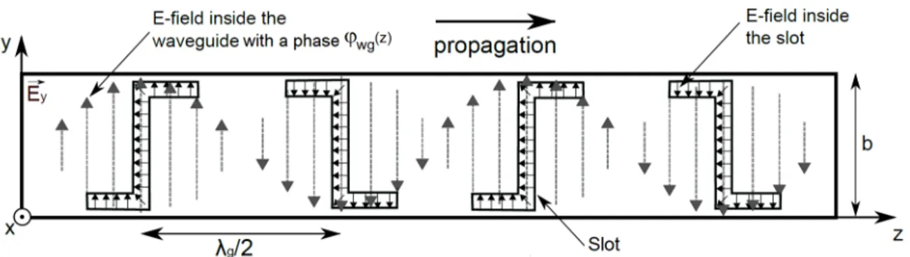
It is important to notice that the orientation of the slots allows us to use both the negative and the positive components of the field (Figure 3). This capability will optimize the size of the antenna, considering the location where and also the location where . Moreover, this capability to use both negative and positive components of the field also prevents grating lobes which appear when the distance is higher than . To take advantage of the alternation of the orientation, the slots have been done on the small side of the waveguide (called ‘b’).
Figure 3: Orientation of the slots to use both positive and negative components of the field
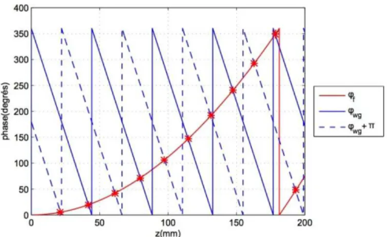
Figure 4 shows , , and as a function of . The slot positions to focus the beam at a distance correspond with intersections indicated by “*”. In this example, , and . The position of each slot is presented in table 2. We have chosen the maximum distance of 500mm between the antenna and the focal point to reach a -10dB beamwidth in the horizontal plane. The number of slots has been chosen to match with the specification of a -10dB beamwidth of 100mm in the vertical plane.
The final structure is a symmetrical centre fed waveguide with 14 slots. A drawing of the antenna is reported in Figure 5.
Figure 4: Determination of the position of each slot on the waveguide
The slots layout is symmetrical according to the feed. The right side slot locations are given in table 2 considering the feed as the reference point.
Table 2: SLOT POSITIONS Slot nº 1 2 3 4 5 6 7 d(mm) 21 42 61 79 97 114 131
Figure 5: Design of the slotted waveguide with CST Microwave Studio
3. SIMULATIONANDMEASUREMENTRESULTS
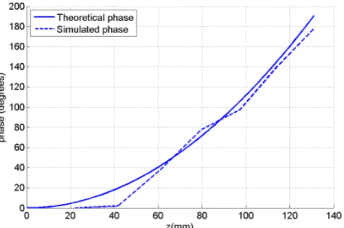
The final slotted waveguide has been simulated using CST Microwave Studio (Figure 5). Loads have been added at the ends of the waveguide to suppress reflected energy and quarter wave transformer inserted to obtain good reflection coefficient (Figure 9). As expressed in the previous section, the insertion of slot on the waveguide can modify the field inside the waveguide and leads to a perturbation of the field and a wrong phase distribution. To verify the impact of the slot on the field inside the waveguide, we represent in figure 6, the desired phase variation along z-axis at the plane where the slots are located and the simulated variation. We can notice small differences in the phase distribution which could lead to a small shift in the plane-wave location.
Figure 6: Theoretical and simulated phase along z-axis in the slots cut-plane
Figure 7 shows the -field results in the E-plane in both amplitude and phase at 9.41GHz. We can notice that the -field is focused with a minimal width for the beam at 360mm from the slotted waveguide. Moreover, at 360mm from the slotted waveguide, we can notice a wavefront locally plane.The difference of focal distance between theory (500mm) and simulation (360mm) can be explained through two different reasons:
• Firstly, as said above and shown in figure 6, the error in the phase distribution due to the wave perturbation inside the waveguide induces by slots insertion, can induce a small difference between the desired and the actual plane-wave position.
• Secondly, the most probable reason of this difference between the theoretical location of the plane-wave and the simulated one is due to the approximation used in the theoretical study. Indeed, the theoretical positions of the slots on the waveguide have been determined through the equation (2). This equation is based on the well-known expression of the phase of the field in function of the distance and the wavelength (φ=2πl/λ). But, as said in the part 2, in the near-field zone, the propagation of the field is more complex than the applied ray-tracing theory which does not take into account coupling between I-slot. Moreover, in the theoretical part, we have considered that each slot radiates an isotropic pattern. All these approximations in the theoretical study can explain the difference with the simulation results. However, the approach presented in this paper has the advantage to be easy to implement with rather good results. Indeed, as shown in figure 7, the beam is focused on a wide range of distance and the error in the position of the plane-wave will have no impact on the system performance.
Figure 7: Simulated electric field in amplitude and phase in the E-plane at 9.41GHz
Indeed, as expressed in references [10, 11], the focus is not a single point, and we can consider that the field is still focus on a large area called the focal depth. Theoretically, the focal depth corresponds to the half power beam size in the axial direction. We can clearly notice in figure 7 that the field is still focused at 500mm from the antenna.
As we can see in figure 8, this focal depth depends on the size of the antenna. When the radiating aperture is very large compared to the wavelength, the focus depth is very small and the focus is closed to a single
point. Conversely, when the aperture becomes smaller (around in our case) the focal depth is larger with a maximum of intensity before the desired focal distance [10, 11].
As reported in table 1, a 10 dB tapering is required in both vertical and horizontal plane for the focused beam at the focal distance. We specify that for the theoretical calculation of the -10dB beamwidth presented in figure 8, we firstly calculate the field radiated by a discrete array of isotropic sources using the following equation (Equation 4) and then, we extract the beamwidth in function of the distance.
(4)
Where, is the number of discrete elements in the aperture, is the wave-number in free space, is the position of the discrete element in the aperture and is the phase of the discrete element in the aperture.
The previous equation considers a linear aperture along z-axis (for x=0), with a uniform amplitude distribution. Each discrete source radiates an isotropic pattern. The variable x represents the distance from the antenna aperture.
Figure 8: Theoretical and simulated beamwidth at -10dB for a radiating aperture equals to (a) and (b)
3.1 Measurement results
A prototype of this antenna has been manufactured as depicted in Figure 9. Figure 9b shows the load inserted at the two ends of the waveguide. We have used a flexible absorbing material (reference ASI 10 from Siepel) held by a metallic square screwed to the waveguide. This absorbing material provides a reflection coefficient of -25dB at 9.41GHz.
The antenna has been measured at 9.41GHz and Figure 10 shows the measured and simulated reflection coefficients of the proposed antenna. The simulation and the measurement are in good agreement with a reflection coefficient lower than -28dB at 9.41GHz.
(a) (b)
Figure 10: Reflection coefficient of the slotted waveguide in simulation and in measurement
Thanks to a back-propagation technique applied to far field measurement results, the -field of the antenna in the near-field region has been determined at 9.41GHz for different distances. Figure 11 shows the mapping of the -field in simulation and in measurement at 100mm, 200mm and 500mm from the slotted waveguide. The dashed line represents the contour of the desired -10dB area with a length of 1530mm and a width of 100mm. For clarity, the simulated and measured spots are drawn in the same graph and shifted along z-axis. Simulation and measurement are considered to be in good agreement, even if small discrepancies can be noticed.
(a) (b)
(c)
Figure 11: Simulated and measured mapping of the normalized -field at 100mm (a), 200mm (b) and
500mm (c) from the slotted waveguide at 9.41GHz
Firstly, a slight tilt of the beam can be observed in measurement results in both planes. In the E-plane, this tilt is equal to 2mm at 100mm from the slotted waveguide and 11mm at 500mm. In the H-plane this tilt is
equal to 2.4mm at 100mm from the slotted waveguide and 12mm at 500mm. This tilt can be explained by a both prototyping errors and slight misalignment of the antenna in the measurement setup.
Secondly, in the H-plane, we can notice that the -10dB beamwidth obtained in measurement is smaller than simulation results. Indeed, at 500mm from the slotted waveguide, the -10dB beamwidth in the H-plane equals to 1307mm in measurement and 1440mm in simulation. This difference is partly due to the post-process which calculates the near-field mapping.
4. CONCLUSION
A near-field focused antenna providing a two dimensional focus beam, with a focus beam in the E-plane and a wide beam in the H-plane, has been investigated in this paper. This slotted waveguide can be easily designed with the formulas given in this paper. The simulation and the measurement are in very good agreement. As shown, this near-field focused antenna can be used as a feed for a linear array with a ratio length/width equal to 15, with a focal point located at from the slotted waveguide.
5. ACKOWLEDGMENTS
The authors warmly thank L. Cronier for the manufacturing of the antenna.
REFERENCES
[1] A. Buffi, P. Nepa, and G. Manara, “Design criteria for near-field focused planar arrays,” Antennas and Propagation Magazine, IEEE, vol. 54,no. 1, pp. 40–50, 2012.
[2] E. Ongareau, E. Marouby, and J. Levrel, “Charts for a quick design of spot-focusing corrugated horn lens antenna,” Antenna and Propagation Society International Symposium, AP-S Digest, vol. 2, pp. 986–989,1994.
[3] P. Piksa and P. Cerny, “Near-field measurement of Gaussian beam behind dielectric lens,” Radioelektronika, 17th International Conference, pp. 1–4, 2007.
[4] I. Ohtera, “Focusing properties of a microwave radiator utilizing a slotted rectangular waveguide,” Transactions on Antennas and Propagation, IEEE, vol. 38, no. 1, pp. 121–124, 1990.
[5] A. Martinez-Ros, J. Gomez-Tornero, F. Clemente-Fernandez, andJ. Monzo-Cabrera, “Microwave near-field focusing properties of width tapered microstrip leaky-wave antenna,” Antennas and Propagation, IEEE Transactions on, vol. 61, no. 6, pp. 2981–2990, June 2013.
[6] J. Gomez-Tornero, F. Quesada-Pereira, A. Alvarez-Melcon, G. Goussetis, A. Weily, and Y. Guo, “Frequency steerable two dimensional focusing using rectilinear leaky-wave lenses,” Antennas and Propagation, IEEE Transactions on, vol. 59, no. 2, pp. 407–415, Feb 2011.
[7] A. Martinez-Ros, J. Gomez-Tornero, and G. Goussetis, “Holographic pattern synthesis with modulated substrate integrated waveguide line source leaky-wave antennas,” Antennas and Propagation, IEEE Transactions on, vol. 61, no. 7, pp. 3466–3474, July 2013.
[8] S. Clauzier, S. Avrillon, L. Le Coq, M. Himdi, F. Colombel, and E. Rochefort, “Near-field focusing in one plane using a loaded sectoral horn antenna,” Progress in Electromagnetics Research Letters, vol. 37,pp. 113–122, 2013.
[9] H. Yee and P. Stellitano, “I-slot characteristics,” IEEE Transactions on Antennas and Propagation, vol. 40, no. 2, pp. 224– 228, 1992.
[10] R. Hansen, “Focal region characteristics of focused array antennas,” Antennas and Propagation, IEEE Transactions on, vol. 33, no. 12, pp.1328–1337, Dec 1985.
[11] I. Sherman, J., “Properties of focused apertures in the Fresnel region,” Antennas and Propagation, IRE Transactions on, vol. 10, no. 4, pp.399–408, July 1962.