Design and Wind Tunnel Testing of a New Concept of Wing
Morphing Camber System
by
David COMMUNIER
MANUSCRIPT-BASED THESIS PRESENTED TO ÉCOLE DE
TECHNOLOGIE SUPÉRIEURE IN PARTIAL FULFILLMENT FOR THE
DEGREE OF DOCTOR OF PHILOSOPHY
Ph.D.
MONTREAL, JUNE 08, 2020
ÉCOLE DE TECHNOLOGIE SUPÉRIEURE
UNIVERSITÉ DU QUÉBEC
This Creative Commons license allows readers to download this work and share it with others as long as the author is credited. The content of this work can’t be modified in any way or used commercially.
BOARD OF EXAMINERS
THIS THESIS HAS BEEN EVALUATED BY THE FOLLOWING BOARD OF EXAMINERS
Mrs. Ruxandra Botez, Thesis Supervisor
Department of System Engineering, École de technologie supérieure
Mr. Tony Wong, Thesis Co-supervisor
Department of System Engineering, École de technologie supérieure
Mr. Henri Champliaud, Chair, Bord of Examiners
Department of Mechanical Engineering, École de technologie supérieure
Mr. Guy Gauthier, Member of the jury
Department of System Engineering, École de technologie supérieure
Mr. Ramin Sedaghati, External Evaluator
Department of Mechanical, Industrial and Aerospace Engineering, Concordia University
THIS THESIS WAS PRESENTED AND DEFENDED
IN THE PRESENCE OF A BOARD OF EXAMINERS AND THE PUBLIC ON MAY 28, 2020
ACKNOWLEDGMENTS
I would like to thank Professor Dr. Ruxandra Botez for allowing me to carry out my master's and my doctorate within the LARCASE and for providing the resources necessary for the realization of my work. As well as Professor. Dr. Tony Wong for having accompanied and advised me in my studies at ÉTS since my first days in the Bachelor of Engineering in automated production.
I would like to thank Oscar for his help in carrying out the experiments necessary for my research and for the advice and support he provided me during my years at LARCASE
I would like to thank all the student interns who participated in this research (Antoine, Aurélien, Bérenger, Enzo, Franck, Joris, Mathieu and Théo). As well as my colleagues from LARCASE, more particularly Alenjandro, Andreea, Georges, Manuel, Marine, Maxime and Oliviu for having accompanied me during all these years.
Finally, I would like to thank my family and especially my wife Amanda and our three sons Louis, Philippe and François for their support during the completion of my doctorate.
Conception et tests en soufflerie d’un nouveau concept de système de déformation de la cambrure de l’aile
David COMMUNIER
RÉSUMÉ
Cette thèse présente la conception et la fabrication d’un nouveau système d’aile déformable réalisé au laboratoire de recherche en commande active, avionique et aéroservoélasticité (LARCASE). Ce système de déformation de l’aile permet de déformer la cambrure de l’aile en modifiant son bord de fuite et son bord d’attaque. Pour permettre cette modification, des fentes ont été réalisées dans les nervures de l’aile, ce qui a permis de les rendre flexibles selon la théorie des mécanismes souples. La résistance structurelle de l’aile a été étudiée avec le module d’analyse par éléments finis (FEA) de Catia V5 en considérant une répartition de pressions sur la surface de l’aile. Les performances aérodynamiques du système de déformation ont été analysées avec le module de calcul de la dynamique des fluides (CFD). La fonctionnalité du système de déformation a été vérifié par des essais statiques en atelier, puis par des essais dynamiques à l’aide de la soufflerie subsonique Price-Païdoussis du LARCASE. Les résultats obtenus à la suite des tests en soufflerie, montrent que le système de déformation de l’aile permet de conserver le contrôle de l’avion en réduisant sa traînée. Le système de déformation permet de conserver la masse de l’aile et il ne demande pas une consommation électrique excessive. Ainsi, la conception d’un système de déformation d’aile présenté dans cette thèse est une bonne option pour permettre de fabriquer des ailes d’avion déformables permettant d’améliorer les performances de l’avion, ce qui nous permet de réduire sa consommation, d’augmenter la durée maximale d’un vol ou d’augmenter la charge utile de l’avion.
Mots-clés : tests en soufflerie, aile déformable, déformation du bord de fuite, déformation du
Design and wind tunnel testing of a new concept of wing morphing camber system
David COMMUNIER
ABSTRACT
This thesis presents the design and manufacturing of a new morphing wing system realized at the Laboratory of Research in Active Controls, Avionics and AeroServoElasticity (LARCASE). This morphing wing system can morph the camber of the wing by modifying its trailing and leading edges. To allow this modification, slots were made in the ribs of the wing, which made them flexible according to the theory of compliant mechanism. The structural strength of the wing was studied with the Finite Element Analysis (FEA) module of Catia V5 software by considering a pressure distribution on the wing surface. The aerodynamic performance of the morphing system was analyzed with the Computational Fluid Dynamics (CFD) module in Ansys-Fluent. The functionality of the morphing system was verified by static tests in the workshop, then by dynamic tests using the LARCASE Price-Paidoussis subsonic wind tunnel. The results obtained from the wind tunnel tests have show that the morphing wing system made it possible to maintain control of the aircraft while reducing its drag. The morphing system made it possible to keep constant the mass of the wing, and it did not require excessive power consumption. Thus, the design for a wing deformation system presented in this thesis is a good option to allow the manufacturing of morphing wings for the aircraft to improve its aerodynamic performance. This design allowed us to reduce fuel consumption, increase the maximum flight time or increase the payload of the aircraft.
Keywords: wind tunnel testing, morphing wing, morphing trailing edge, morphing leading
TABLE OF CONTENTS
Page
INTRODUCTION ...1
LITERATURE REVIEW ...23
1.1 Morphing wings at LARCASE at ÉTS ...23
1.2 The different types of morphing wing ...25
1.2.1 Wing aspect ratio ... 25
1.2.2 Morphing of the camber... 25
1.2.3 Morphing of the trailing edge ... 27
1.2.4 Morphing of the leading edge ... 28
1.2.5 Morphing with compliant mechanisms ... 28
1.3 Design constraints ...29
RESEARCH APPROACH AND THESIS ORGANIZATION ...31
2.1 Research approach ...31
2.2 Thesis organization ...32
EXPERIMENTAL VALIDATION OF A NEW MORPHING TRAILING EDGE SYSTEM USING PRICE – PAÏDOUSSIS WIND TUNNEL TESTS ...35
3.1 Introduction ...36
3.2 Design of the Morphing Wing System ...38
3.2.1 Deformation of the Camber ... 38
3.2.2 Deformation of the Trailing Edge ... 39
3.3 Sizing design and control of the MTE ...44
3.3.1 Sizing design ... 44
3.3.2 MTE control ... 46
3.4 Manufacturing and wind tunnel testing ...48
3.4.1 Manufacturing of the MTE system ... 48
3.4.2 Wind Tunnel Tests ... 49
3.5 Comparison of aerodynamics coefficients for a MTE versus a conventional aileron .63 3.5.1 Comparison of aerodynamics coefficients ... 65
3.5.2 Electrical consumption ... 68
3.6 Conclusion ...69
DESIGN, MANUFACTURING AND TESTING OF A NEW CONCEPT FOR A MORPHING LEADING EDGE USING A SUBSONIC BLOW DOWN WIND TUNNEL ...71
4.1 Introduction ...72
4.2 Design of the MLE...76
4.3 Structural Analysis of the MLE System ...81
4.5 Wind Tunnel Tests Results ...97
4.6 Aerodynamic simulation of the wing ...102
4.7 Conclusion and further work ...114
DESIGN AND VALIDATION OF A NEW MORPHING CAMBER SYSTEM BY TESTING WITH THE SUBSONIC PRICE – PAÏDOUSSIS WIND TUNNEL ...117
5.1 Introduction ...118
5.2 Problem statement ...120
5.3 Design of the Morphing Camber System...122
5.4 Prototype manufacturing ...128
5.5 The Price – Païdoussis wind tunnel ...130
5.6 Result ...132
5.7 Discussion ...135
5.8 Application of results with the UAS-S4 Ehécatl ...137
5.9 Conclusion ...148
DISCUSSION OF RESULTS...151
CONCLUSION AND RECOMMENDATIONS ...157
LIST OF TABLES
Page
Table 0.1 Characteristics of UAS S4 Ehécatl ...1
Table 3.1 Range and resolution for ATI Omega 160 F/T sensor ...52
Table 3.2 Size of the slits in the deformable rib ...55
Table 4.1 Dimensions of the slits ...85
Table 4.2 NEMA 23 Bipolar Stepper product specification ...90
Table 4.3 Range and resolution for ATI Omega 160 force and torque (F/T) sensor. Fx,y,z represent the forces and Tx,y,z represent the torques ...90
Table 4.4 PhidgetStepper Bipolar HC product specification ...96
Table 5.1 Slits’ dimensions on the trailing edge of the rib ...123
Table 5.2 Slits’ dimensions on the leading edge of the rib ...123
Table 5.3 MTE tip displacement values according to the servomotor angle of rotation ...125
Table 5.4 Morphing cases studied in wind tunnel ...132
Table 5.5 Geometric data of the UAS-S4 ...137
Table 5.6 Equation of lift coefficient variation with angle of attack ...139
Table 5.7 Values of clα for each studied case ...140
LIST OF FIGURES
Page
Figure 0.1 UAS-S4 Ehécatl of Hydra Technologies ...2
Figure 0.2 Airfoil NACA0012 (red) and airfoil NACA4412 (green) superimposed ....4
Figure 0.3 Lift coefficient variation with the angle of attack for NACA0012 and NACA4412 airfoil for Reynolds numbers of 150,000 to 600,000 ...6
Figure 0.4 Zoom of lift coefficient variation with the angle of attack for NACA0012 and NACA4412 airfoils for Reynolds number from 150,000 to 600,000 ...7
Figure 0.5 Drag coefficient variation with the angle of attack for the NACA4412 airfoil (red) and for the NACA0012 airfoil (blue) at a Reynolds number of 500,000 ...8
Figure 0.6 Methodology’s main steps ...9
Figure 0.7 Step 1: List of systems ...10
Figure 0.8 Step 2: Systems analysis ...11
Figure 0.9 Step 3: Systems design...12
Figure 0.10 Step 4: Systems manufacturing ...12
Figure 0.11 Step 5: Systems wind tunnel testing ...13
Figure 0.12 Step 6: Integration in the UAS-S4 ...13
Figure 0.13 Side view of the reference wing ...16
Figure 0.14 Top view of the reference wing ...16
Figure 0.15 Variation of the drag coefficient with the angle of attack measured in the wind tunnel and calculated theoretically ...18
Figure 0.16 Variation of the lift coefficient with the angle of attack measured in the wind tunnel and calculated theoretically ...20
Figure 0.17 Variation of the pitch coefficient with the angle of attack measured in the wind tunnel and calculated theoretically ...21
Figure 3.1 Control of the trailing edge rib deformation ...41
Figure 3.2 Deformed rib in CATIA V5 ...41
Figure 3.3 NACA0012 airfoil with inclined aileron a) and with MTE b) ...41
Figure 3.4 Comparation of the performance of a wing with inclined aileron and MTE ...43
Figure 3.5 Deformation of the rib ...46
Figure 3.6 FEA of MTE control under aerodynamical pressures ...47
Figure 3.7 Servomotor specifications ...47
Figure 3.8 Structure of the MTE system ...48
Figure 3.9 Prototype with a MTE system...48
Figure 3.10 Reference rigid wing dimensions...50
Figure 3.11 LARCASE Price-Païdoussis subsonic wind tunnel ...51
Figure 3.12 Drag coefficients variation with angle of attack for the reference wing...52
Figure 3.13 Lift coefficients variation with angle of attack for the reference wing...53
Figure 3.14 Pitch coefficients variation with angle of attack for the reference wing...54
Figure 3.15 Size and location of the slits in the MTE rib (unit: in) ...55
Figure 3.16 0.75 in displacement of the trailing edge tip (19.05 mm) for a 7° rotation ...56
Figure 3.17 Controlling distance ...57
Figure 3.18 Test wing with MTE ...57
Figure 3.19 Influence of the MTE on the drag coefficient at 15 m/s (49.21 ft/s) ...58
XVII
Figure 3.21 Experiment 2 tapes covering the intersection between the morphing
fixed parts were removed ...59
Figure 3.22 Experiment 3 with tapes installed on one side of the slits (deflector) ...60
Figure 3.23 Experiment 4 with tapes installed on both sides of the slits ...60
Figure 3.24 𝐶𝑑 variation with the angles of attack at the speed of 15 m/s (49.21 ft/s) ...62
Figure 3.25 Zoom-in of the drag coefficients variation with the angles of attack between -8° and 8° ...62
Figure 3.26 Wing L/D ratio variation with the angle of attack ...63
Figure 3.27 2D plan of the wing with an aileron ...64
Figure 3.28 𝐶𝐿 and 𝐶𝐷 variation with the angle of attack. At 15 m/s (49.21 ft/s) for each system ...66
Figure 3.29 L/D ratio variation with the angle of attack at 15 m/s (49.21 ft/s) for each system ...67
Figure 3.30 𝐶𝑑 variation with angle of attack- zoomed-in around 0° ...67
Figure 3.31 L/D ratio variation with angle of attack- zoomed-in around 0° ...68
Figure 4.1 Drag coefficient variation with lift coefficient (experimental values). Legend: MTE, morphing trailing edge ...73
Figure 4.2 Morphing of camber: NACA0012 airfoil (grey) and NACA4412 airfoil (black) ...74
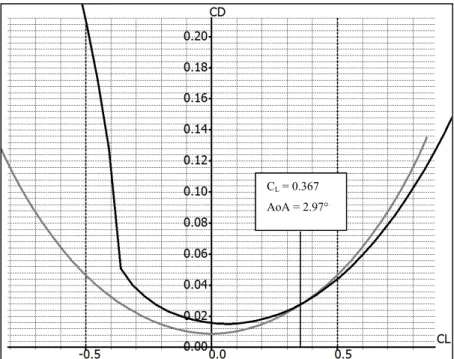
Figure 4.3 Drag coefficient variation with lift coefficient variation for NACA0012 (grey) and NACA4412 (black) (computed values). The curves intersect for a lift coefficient CL = 0.367 and for an angle of attack AoA = 2.97° ...74
Figure 4.4 Internal structure of the wing ...77
Figure 4.5 Morphing leading edge (MLE) system ...78
Figure 4.7 Control arm through the main spar ...79
Figure 4.8 Slits on wing surface ...79
Figure 4.9 Impact of the slits on wing drag ...80
Figure 4.10 Prototype of the MLE for wind tunnel testing ...81
Figure 4.11 Slit parameter definitions. l = width of the slit, p = depth of the slit, L = distance between the slit and the LE, e = airfoil thickness and t = thickness at bottom of the slit ...82
Figure 4.12 MLE with the aerodynamic loads around the wing ...83
Figure 4.13 Finite element analysis (FEA) structural mesh of the MLE system ...84
Figure 4.14 FEA of the Structure of the MLE system ...85
Figure 4.15 Maximum displacement of the MLE tip ...86
Figure 4.16 Maximum displacement values of the MLE tip ...87
Figure 4.17 Test wing in the Price - Païdoussis subsonic wind tunnel ...88
Figure 4.18 Price - Païdoussis subsonic blow down wind tunnel dimensions ...88
Figure 4.19 Section of the Price-Païdoussis subsonic wind tunnel of the Laboratory of Applied Research in Active Controls, Avionics, and AeroServoElasticity (LARCASE) ...89
Figure 4.20 Internal mechanism of the aerodynamic loading scales ...91
Figure 4.21 Upper disc of the aerodynamic loading scales ...92
Figure 4.22 Leading edge (LE) of the prototype in its morphed configuration ...93
Figure 4.23 LabVIEW interface ...94
Figure 4.24 Display of forces read by F/T sensor ...94
Figure 4.25 Disc angle controller ...95
Figure 4.26 Servomotor controller ...95
XIX
Figure 4.28 Variation of the lift coefficient with morphing angle of the MLE ...99
Figure 4.29 Variation of the drag coefficient with angle of attack ...100
Figure 4.30 Variation of the drag coefficient with morphing angle of the MLE ...101
Figure 4.31 Variation of the lift on drag (L/D) ratio with angle of attack ...101
Figure 4.32 Wing with 4 mm displacement of LE tip ...103
Figure 4.33 Model of wing with MLE ...103
Figure 4.34 Fluid domain of the simulation ...104
Figure 4.35 Fluent simulation ...104
Figure 4.36 Fluid domain mesh of the simulation ...105
Figure 4.37 Lift coefficient variation with angle of attack ...106
Figure 4.38 Drag coefficient variation with angle of attack ...107
Figure 4.39 Drag variation with angle of attack for MLE at 0° ...107
Figure 4.40 Drag coefficient variation with angle of attack with experimental values shift by 3° ...108
Figure 4.41 MLE with grooves and bumps ...109
Figure 4.42 Lift coefficient variation with angle of attack for improve modeling ...110
Figure 4.43 Drag coefficient variation with angle of attack for improved modeling ...110
Figure 4.44 Pressure around the wing with MLE at 18° with an airspeed of 20 m/s and (a) angle of attack 0°, (b) angle of attack 10°, and (c) angle of attack 18° ...111
Figure 4.45 Velocity vector around the wing with MLE at 18° with an airspeed of 20 m/s and (a) angle of attack 0°, (b) angle of attack 10°, and (c) angle of attack 18° ...112
Figure 4.46 Velocity streamlines for an angle of attack of 8° and the MTE
at 18° ...113
Figure 5.1 NACA0012 and NACA4412 airfoil superimposed ...121
Figure 5.2 Drag coefficient variation with the lift coefficient for NACA0012 (grey) and NACA4412 (black). For CL = 0.367, angle of attack of NACA0012 = 7.8° and angle of attack of NACA4412 = 2.97° ...121
Figure 5.3 MLE tip maximum displacement of 0.333 in (8.46 mm) ...124
Figure 5.4 MTE tip displacement of 1.01 in (25.65 mm) for a 10° rotation of servomotor ...124
Figure 5.5 MTE system ...125
Figure 5.6 MLE system ...126
Figure 5.7 MC system ...126
Figure 5.8 MC system internal assembly ...127
Figure 5.9 Morphing ribs place in the manufacturing guide ...128
Figure 5.10 Central section of the wing corresponding to the MC system ...129
Figure 5.11 Leading edge mold ...129
Figure 5.12 Price - Païdoussis subsonic wind tunnel of LARCASE...130
Figure 5.13 Dimensions of the Price - Païdoussis subsonic wind tunnel ...130
Figure 5.14 Dimension of the test chamber of the wind tunnel ...131
Figure 5.15 Aerodynamic loading scales ...132
Figure 5.16 Drag coefficient variation with the angle of attack ...133
Figure 5.17 Lift coefficient variation with the angle of attack ...133
Figure 5.18 Lift on drag ratio variation with the angle of attack ...134
Figure 5.19 Lift coefficient variation with the angle of attack around the stall angle ...135
XXI
Figure 5.20 Drag coefficient variation with the lift coefficient variation ...136
Figure 5.21 Lift coefficient variation curve with the angle of attack ...139
Figure 5.22 Induce drag coefficient variation with the angle of attack ...141
Figure 5.23 Equation of drag coefficient variation with angle of attack ...142
Figure 5.24 Skin friction drag variation with the angle of attack ...142
Figure 5.25 Lift coefficient variation with angle of attack for the UAS-S4 wing ...145
Figure 5.26 Lift coefficient variation with angle of attack for UAS-S4 (wing + fuselage) ...145
Figure 5.27 Drag coefficient variation with the angle of attack for UAS-S4 ...146
Figure 5.28 Drag coefficient variation with the lift coefficient for the UAS-S4 ...147
Figure 5.29 Drag coefficient variation with the lift coefficient for UAS-S4 (zoom) ...147
Figure 6.1 Shapes of NACA0012, NACA4411, NACA4412 and MLE ...152
Figure 6.2 Lift coefficient variation with the angle of attack (theoretical using XFLR5 code) ...153
Figure 6.3 Drag coefficient variation with the angle of attack (theoretical) ...154
LIST OF ABREVIATIONS
AIAA American Institute of Aeronautics and Astronautics CASI Canadian Aeronautics and Space Institute
CFD Computational Fluid Dynamics CIRA Italian Center for Aerospace Research
CRIAQ Consortium for Research and Innovation in Aerospace in Quebec ÉTS École de technologie supérieure
F/T Force and Torque
LARCASE Laboratory of Research in Active Controls, Avionics and AeroServoElasticity
LE Leading Edge
LLT Lifting Line Theory
L/D Lift on Drag
MCS Morphing Camber System
MDO Multidisciplinary Design Optimization MLE Morphing Leading Edge
MTE Morphing Trailing Edge
NACA National Advisory Committee for Aeronautics
NRC-IAR National Research Council - Institute for Aerospace Research NSERC Natural Sciences and Engineering Research Council of Canada AWACS Airborne Warning and Control System
SMA Smart Material Actuators
UAV Unmanned Aerial Vehicle
LIST OF SYMBOLS BASIC UNIT
m meter (unit length)
A Ampere (unit of electric
current intensity) Area m² square meter GEOMETRIC UNIT Length International System km kilometer mm millimeter Imperial System in inch (= 0.0254 m) ft feet (= 12 in) MASS UNIT Mass International System g gram kg kilogram Imperial lb pound (= 0,453 kg) Density
kg/m³ kilogram per cubic meter
MECHANICAL UNIT
Speed
International System
m/s meter par second km/h kilometer per hour steps/sec step motor per second Imperial
kn knot (= 1.852 km/h)
ft/s feet per second (= 0,3048 m/s)
RPM round per minute
Acceleration
step motor for second square Angle plan
° degree rad radian
steps step motor
Viscosity
Kg/(m.s) kilogram per meter-second Forces International System N newton (= 1 kg.m/s²) Moment International System Nm newton meter kg.cm kilogram centimeter
kg/cm kilogram per centimeter Imperial
lbf-in pound-force inch (=
0,1129848 Nm)
oz/in once per inch
Imperial
lbf pound-force (= 4,44822 N)
TIME UNIT
h hour
ELECTRIC UNIT
Electric current voltage
V volts Current intensity
mA milliampere mΩ milliohms Inductance
mH millihenry Diameter of an electric cable
AWG American Wire Gauge
Electric power W watt mW milliwatt kW kilowatt Heat unit °C degree Celsius
INTRODUCTION
This thesis presents research results obtained for the development of a morphing camber system for an UAV wing. The different steps to achieve this morphing system are described through three papers published in scientific journals. These papers describe the design, manufacturing and the experimental tests carried out using the morphing. By this design, the morphing system presented can be improved in order to make it more efficient but also to be used in the design of UAV by the reader of this thesis, or by the published papers within the framework of this thesis.
0.1 UAS-S4 Ehécatl – study aircraft
The Unmanned Aerial System (UAS) S4 Ehécatl is an autonomous flight system, that includes an onboard camera, an autopilot and the sensors necessary for its operation. The UAS-S4 Ehécatl model was developed in Mexico by Hydra Technologies in 2002 and made its first flight in 2006. UAS-S4 Ehécatl is used by the Mexican Army and Police. As part of the research developed at the research laboratory in active control, avionics and aeroservoelasticity (LARCASE), new methods of analysis, design and manufacturing applied to morphing wings, were developed. The main parameters of the UAS-S4 Ehécatl are as follows:
Table 0.1 Characteristics of UAS S4 Ehécatl
Span 12 pi 2 po (3.7 m)
Maximum takeoff weight 120 lb (54.43 kg)
Maximum speed 90 kn (167 km/h)
Cruise speed 38 kn (70 km/h)
Figure 0.1 shows the UAS-S4 Ehécatl from the LARCASE laboratory. This version is used to take accurate measurements of the UAS-S4 Ehécatl to perform structural and aerodynamic analyses. Another UAS-S4 identical version is kept in Mexico, and it will be used for its flight tests.
0.2 Problematics
With its surveillance function, the UAS S4 Ehécatl performs irregular flights, for which, flight conditions change frequently and significantly. Two flight conditions prevail in the flight of the UAS: the "slow flight" which allows the UAS to observe the area, and the "fast flight" which allows the UAS to fly from one observation zone to another. In this thesis, the wind tunnel results were obtained at 20 m/s, which is the speed corresponding to the slow flight of the UAS.
For a classical UAS, the wing is fixed. An airfoil, and thus a wing shape were chosen, and thus considered during the design of the UAS. As the UAS flies through different phases (ascent, descent, cruising), a compromise is considered to obtain the best efficiency of the global flight. This compromise induces a loss of efficiency for the flight phases for which the
3
wing would not optimise. This loss of efficiency results in higher fuel consumption and / or a lower battery life.
The main problem currently area is the inability to change a wing airfoil from one theoretical airfoil to another. Current morphing systems do not experimentally allow the wing to achieve its desired form calculated theoretically using Computational Fluid Dynamics (CFD). The first problem is that the aerodynamic team must therefore work, and interact continuously with the structural team, because of the fact that the deformations obtained experimentally by the structural team must be analyzed by the aerodynamics team in order to quantify the aerodynamic performances. Therefore, an aero-structural optimized model will be design. It was found very difficult to obtain, from the experimental point of view, the structural deformations desired by the aerodynamic team initially.
The second problem is the mass of morphing systems that increase the weight of the UAS, because morphing wing systems generally need a more complex structure than a classical wing (more parts). If the morphing system did not replace or use actuators already present in the classical wing, it will give an additional weight for the wing. Thus, the gain obtained by the morphing system is lost by the weight of the system. We must also be able to solve this second problem.
The third problem concerns the consumption energy of the morphing system. The use of a morphing system aims to reduce to the power consumption due to the drag forces. But the use of the morphing wing system usually implied an energy consumption higher than that of a classical wing. In order to be used, the morphing system must imply an increase of the energy consumed lower than the reduction in the consumed power energy.
Thus, the originality of this new research in the field of morphing wings consists in the resolution of these three problems by used of new methodologies of aero-structural design, and by their experimental validation using the Price-Païdoussis subsonic blow down wind tunnel.
0.3 Objective
The objective of the research presented in this thesis is to design a mechanical morphing wing system that significantly modifies the wing airfoil. This significant deformation was defined by the ability of the system to change the shape of a wing using the NACA0012 airfoil to its shape using the NACA4412 airfoil (Figure 0.2).
Figure 0.2 Airfoil NACA0012 (red) and airfoil NACA4412 (green) superimposed
A deformation defined in Figure 0.2 increases the lift as well as the drag of the wing. The lift increase allows the UAS to fly at a lower angle of attack, which reduces its drag. A morphing system will be considered “effective” if the drag reduction due to the reduction of the angle of attack is greater than the drag increase due to the deformation of the wing. As the lift required for an UAS depends on its flight case, the lift is considered fixed during the study of a flight case, so that we seek to reduce the corresponding drag.
As seen in the problematic section, morphing wing systems often have the disadvantage of increasing the mass of the UAS due to additional sensors and actuators. This increase in the mass of the UAS results in a higher lift needed to fly and therefore in an increase of the angle of attack of the UAS. This increase therefore counteracts the reduction of the angle of attack obtained due to the morphing wing system. Thus, an increase in the mass of the aircraft will therefore reduce the efficiency of the system or make it inefficient, that it would result in an increase in the drag of the UAS. A system must be designed that keeps constant the total mass of the UAS or minimizes the increase in its mass.
5
In addition to conserve the mass of the aircraft, the increase in electric current of the UAS must be minimized. Too much power consumption causes an increase in the fuel consumption of the UAS engine, which is equivalent to an increase in the total drag of the aircraft.
As a result of this airfoil change, an increase of the wing lift would have a lower impact on wing drag than with the deflection of an aileron. This change will allow us to reduce drag during turn and thus to reduce the effect of reverse roll a the UAS. In addition, the shape of the wing would be changed to adapt it to different flight conditions. In the “take-off acceleration” phase, reduced drag is needed so the NACA0012 airfoil will be appropriate. When the pilot decides to take-off, the airfoil used will be that of NACA4412 which will reduce the take-off distance and fuel consumption. Gradually during the flight of the UAS, the NACA4412 airfoil will change to NACA0012 airfoil. Therefore, it will be possible to save fuel during flight and take-off. When the UAS enters observation flight, the wing can take the shape of NACA4412 airfoil which will allow a slower flight, and thus obtain a better observation of the ground. For the first prototype, these standard airfoils will be used. We will adapt it to the profiles used by UAS-S4 thereafter.
To better understand the effectiveness of this research idea, the performance curves of both NACA0012 and NACA4412 airfoils are plotted using the XFLR5 code for Reynolds number of 150,000 to 600,000. The performance curves shown in Figure 0.3 the variations of the lift and drag coefficients as functions of the angle of attack.
The first observation is that the NACA4412 airfoil offers a gain of up to 0.5 on the lift coefficient. The two curves are parallel on their linear part (straight lines) and the stall angle of attack for the NACA4412 airfoil is higher than the stall angle for the NACA0012 airfoil.
Figure 0.3 Lift coefficient variation with the angle of attack for NACA0012 and NACA4412 airfoil for Reynolds numbers of 150,000 to 600,000
NACA4412
7
In Figure 0.4, the lift coefficient of the NACA4412 airfoil is 0.46 for an angle of 0 °. To obtain the same coefficient with the NACA0012 airfoil, the angle of attack should be 4°. Which means that by changing the shape of the wing from NACA0012 airfoil to NACA4412 airfoil, the angle of attack of the UAS could be reduce by 4°.
Figure 0.4 Zoom of lift coefficient variation with the angle of attack for NACA0012 and NACA4412 airfoils for Reynolds number from 150,000 to 600,000
NACA4412
The drag coefficient of the NACA4412 airfoil for the angle of attack of 0° is 0.0088 at the Reynolds number of 500 000. The drag coefficient of the NACA0012 airfoil for an angle of attack of 4° is 0.0092 at the Reynolds number of 500 000. We see a 4% gain on the drag coefficient. By changing the shape of the wing airfoil, we can increase the lift of the wing with a smaller influence on the drag than if only the angle of attack of the wing is changed. In an hypothetical case where we would need a 4° angle of attack to take-off using a NACA0012 airfoil, it will be possible to take-off without changing the angle of attack but only by changing NACA0012 airfoil shape into NACA4412 airfoil. However, the drag coefficient of the NACA4412 airfoil at 0° is smaller than the drag coefficient of the
Figure 0.5 Drag coefficient variation with the angle of attack for the NACA4412 airfoil (red) and for the NACA0012 airfoil (blue) at a Reynolds number of 500,000
9
NACA0012 airfoil at 4° angle of attack, therefore a gain on the drag coefficient of the airfoil can be obtained during the take-off. A gain from the reduction of the angle of attack of the other part of the UAS (fuselage, empennage, …) can be added to the gain obtained from the wing. This example illustrates the potential gain of such a system during the take-off phase, in which its impact will be a shorter take-off phase and a lower fuel consumption.
0.4 Methodology
0.4.1 Main Steps
The work methodology is broken down into the following six main steps (Figure 0.6). At the end of each step, a selection process is carried out to refine our list of possible solutions defined in the first step of the following methodology described in Figure 0.6. At the end of step 5, one single solution will be retained in order to implement it in the structure of the UAS-S4 in the step 6.
The first step of this research (Figure 0.7) consists in studying the existing morphing systems. Teams from our laboratory and from other labs are also researching morphing wings. Therefore, to accelerate our research, we have analyzed the works and conclusions of other laboratories on other morphing systems to determine if these systems were working in accordance with our objectives. From these studies, we were be able to establish in step one a list of morphing systems, as seen in Figure 0.7.
Figure 0.7 Step 1: List of systems
During second step, different morphing systems were compared from the list defined in the first step. The two main criteria of this comparison were the feasibility and the effectiveness of the solution. As shown in Figure 0.8, the feasibility was determined by the possibility of manufacturing the system, so that it would fit into the wing of the UAS-S4 Ehécatl while its effectiveness was determined by its positive influence on the aerodynamic performance of the wing. Our goal was to achieve a lower drag with the morphing system than with the actual classical system of the UAS-S4.
The UAS-S4 has a certain wing configuration and therefore some morphing systems can not be applied on it because of the fact that the space is too small in this configuration. As mentioned above, the existing studied morphing systems do not all have the same objectives, and therefore their effectiveness in our research is not guaranteed. We need to analyze which surface of the wing is morphing and how it affects the UAS-S4 aerodynamic performance. Thus, the advantages and disadvantages of these analyses are determined.
11
Figure 0.8 Step 2: Systems analysis
The third step consists in the selection of the best solutions for our application, and thus in further studies of these solutions. In Figure 0.9, it is shown that each selected solution must be designed it into a morphing wing system. This step is the most difficult because of the fat that the mechanical problems related to an experimental morphing system should be solved in the design phase. Such a problem would be the existence of waves on the surface of the wing during its deformation. These waves would be caused by the interaction of the structure with actuators, if these actuators would be punctually distributed.
Figure 0.9 Step 3: Systems design
The fourth step is the manufacturing of the selected systems. To compare the effects of these systems on morphing wings, these morphing wings will be equipped with different systems, and further manufactured. These tasks are shown in Figure 0.10.
Figure 0.10 Step 4: Systems manufacturing
During the fifth step (Figure 0.11), the wind tunnel tests of morphing wings will be performed and the results obtained as function of aerodynamic performance will be analyzed. The flow of air will be simulated around the morphing wing and the aerodynamic forces will be calculated and compared with those obtained during wind tunnel tests.
13
Figure 0.11 Step 5: Systems wind tunnel testing
The sixth and final step (Figure 0.12) will, based on the experimental results, select the most effective morphing system with respect to our drag reduction objective, and would integrate it into the wing of the UAS-S4.
Figure 0.12 Step 6: Integration in the UAS-S4
The design and manufacturing of the morphing wing systems will be detailed in the following subsections.
0.4.2 Design phases of a morphing wing system
In order to realize the design of a morphing system, three phases are chosen. The first phase consists in a study of the morphing system influence on the aerodynamic performance of the wing. During this step, the type of aerodynamic performance improvement is determined for the wing, and thus the effective position of the morphing system in the wing. This "effective position" will be obtained following the displacement of the morphing system with respect to the chord and to the calculation of the aerodynamic coefficients on the morphing wing. The most effective position will be the one for which the lift on drag (L/D) ratio will be the highest. The aerodynamic coefficients calculations will be performed using well known software such as Xfoil, Fluent, etc. XFoil is an open source code that calculates the aerodynamic performance of a wing airfoil (2D), and it has the advantage of its easy integration into an optimization code (Gabor, Koreanschi, & Botez, 2012). Fluent is an Ansys tool that calculates the aerodynamic coefficients of a 3D flow around the wing.
During the second phase, a design of the system was made, located in the area of the wing obtained during the first step. From this design, the possible structural deformation of the wing was determined using Finite Element Analysis (FEA) (Nastran, Hyperworks, CATIA V5). During this phase, the positions of the actuators, were determined.
During the third phase, an aerodynamic analysis of the wing was performed by use of the deformation obtained previously using either the "3D Panels" calculation method in XFLR5 code or the FEA in Fluent-Ansys. XFLR5 is an "open source" software that is used for aerodynamic calculations on aircraft (Fraqueiro, Albuquerque, & Gamboa, 2016) (wings, horizontal and vertical stabilizer and fuselage), as well as for the aircraft stability. It allows the user to perform an aerodynamic analysis of the aircraft according to three methods of calculation: Lifting Line Theory (LLT) (Phillips & Snyder, 2000), Vortex Lattice Method (VLM) (Konstadinopoulos, Thrasher, Mook, Nayfeh, & Watson, 1985) and 3D Panels (Katz & Plotkin, 2001).
15
The numerical results were validated by wind tunnel tests on the morphing wings. These morphing wings will have the same dimensions as the reference wing (Figure 0.13), and will allow us to compare the impact of the system on the morphing wing with respect to its impact on same wing without actuating system (or reference wing). The reference wing has the NACA0012 airfoil with a 10 in chord, and a 11.5 in wingspan. The 10 in chord was chosen following the ATR42 test wing project, in which a 10 in chord was also chosen ( (Ben Mosbah, Botez, & Dao, 2014), (Ben Mosbah, Botez, & Dao, 2016)). The wingspan is 12 in, which is half of the height of the test chamber, but 0.5 in are embedded in the wing base, that attaches the model to the aerodynamic loading scales. This is the reason why the analysis is done on a wing with a span of 11.5 in.
The initial objective of the reference wing described above was to validate the operation of our new aerodynamic loading scales by comparing the measured values with the numerical values of the loads (forces and moments). Figure 0.13 and Figure 0.14 show the dimensions of the reference wing. In Figure 0.13, the chord of the wing is 10 in, the span of the wing is 11.5 in, the diameter of the wing base is 10.7 in and the thickness of the wing base is 0.5 in. In Figure 0.14, it can be seen that the shape of the wing base is circular while the airfoil of the wing is NACA0012.
Wind tunnel tests were conducted on this reference wing as part of my Master’s thesis (Communier, 2015). The experimental aerodynamic performance was validated by its comparaison with the numerical values calculated by use of XFLR5 software. Figure 0.15 to
Figure 0.13 Side view of the reference wing
17
Figure 0.17 show the experimental wind tunnel tests results obtained for wing with respect to the numerical results. These results were expressed as function of lift coefficient and drag coefficient. The tests were conducted in a rectangular section chamber (2 ft per 4 ft) at flow speeds of 20 m/s, 25 m/s, 30 m/s, and 35 m/s. The angle of attack of the wing varied from -10° to 20° in intervals of 1°. The measurements were made by an aerodynamic loading scales including a Mini45-E transducer from ATI Industrial Automation. This aerodynamic loading scales was designed by the LARCASE team. The theoretical values of the reference wing were calculated using the XFLR5 code for a wing of a span of 11.5 in and a 10 in chord by the "3D Panels" calculation method of XFLR5. As our wing in the wind tunnel is in contact with the floor of the test chamber, this contact is simulated by a symmetry of the wingspan considered in the XFLR5 software. Therefore, the wing has a total span of 23 in. Figure 0.15 shows the variation of the measured versus calculated drag coefficients of the wing with the angle of attack.
Figure 0.15 Variation of the drag coefficient with the angle of attack measured in the wind tunnel and calculated theoretically
In Figure 0.15, the curves of variation of the drag coefficient with the angle of attack are superimposed for positive angles of attack, but a slight asymmetry is observed for the negative angles. These results include a correction coefficient presented in equation (0.1) and detailed in the Master's thesis (Communier, 2015), as well as in the AIAA conference paper (Communier, Flores Salinas, Carranza Moyao, & Botez, 2015). This coefficient is composed of a static part and a dynamic one. The static part result from the contact surface between the aerodynamic loading scales base and the air flow. The dynamic part varies with the angle of
0 0,05 0,1 0,15 0,2 0,25 0,3 -15 -10 -5 0 5 10 15 20 25 Coefficient of Drag Cd
Angle of attack (deg)
Cd vs angle of attack exp 20m/s Cd vs angle of attack exp 25m/s Cd vs angle of attack exp 30m/s Cd vs angle of attack exp 35m/s Cd vs angle of attack th 20m/s Cd vs angle of attack th 25m/s Cd vs angle of attack th 30m/s Cd vs angle of attack th 35m/s
19
the wing and the speed of the air flow. This dynamic part was determined by measurements. According to the aerodynamics coefficients computation theory at low speed, the aerodynamic coefficient is constant as a function of the speed. However, in the measurements, a divergence of the drag coefficient was observed as a function of the speed. By using a subtraction of the drag coefficients curves between them, it was possible to determine proportionality between the divergence and the air flow speed, as well as between the angle of attack (𝛼) and the air flow speed (𝑣).
𝐼𝑓 𝑣 ≤ 20 𝑚 𝑠⁄ Then correction = 0.022
Else correction = −0.00012 × |𝛼| + 0.0003 × 𝑣 − 20 + 0.022
(0.1)
Figure 0.16 shows the variation of the lift coefficient of the wing with the angle of attack. A small difference between the lift coefficient calculated and the lift coefficients experimentally determined was found at angles greater than 15°, thus close to stall. This difference is explained by a loss of precision in the calculations for stall condition (high angle of attack).
Figure 0.16 Variation of the lift coefficient with the angle of attack measured in the wind tunnel and calculated theoretically
The theoretical pitch coefficients were calculated at 25% of the chord while their experimental measurements are performed at 50% of the chord. This position of 50% of the chord came from the position of the sensor that is place in the center of the aerodynamic scales and the wing is centered on the aerodynamic scale. Therefore, we carried out a conversion to find the equivalent measured values to 25% of the chord. This conversion was
-0,8 -0,6 -0,4 -0,2 0 0,2 0,4 0,6 0,8 1 1,2 -15Coefficient of -10 -5 0 5 10 15 20 25 Lift Cl
Angle of attack (deg)
Cl vs angle of attack exp 20m/s Cl vs angle of attack exp 25m/s Cl vs angle of attack exp 30m/s Cl vs angle of attack exp 35m/s Cl vs angle of attack th 20m/s Cl vs angle of attack th 25m/s Cl vs angle of attack th 30m/s Cl vs angle of attack th 35m/s
21
given by a simplified equation (equation (0.2)), so differences exist for angles of attack below 1° and over 11° between the results obtained by calculation, and by wind tunnel tests (Figure 0.17).In equation (0.2), 𝐶 / represents the pitch coefficient at 25% of the chord, 𝐶 / represents the pitch coefficient at 50% of the chord and 𝐶 represents the lift coefficient.
𝐶 / = 𝐶 / +𝑐ℎ𝑜𝑟𝑑 4 × 𝐶
(0.2)
Figure 0.17 Variation of the pitch coefficient with the angle of attack measured in the wind tunnel and calculated theoretically
-0,2 -0,15 -0,1 -0,05 0 0,05 0,1 0,15 -15 -10 -5 0 5 10 15 20 25 Coefficient of pitch Cm
Angle of attack (deg)
Cm vs angla of attack exp 20m/s Cm vs angla of attack exp 25m/s Cm vs angla of attack exp 30m/s Cm vs angla of attack exp 35m/s Cm vs angla of attack th 20m/s Cm vs angla of attack th 25m/s Cm vs angla of attack th 30m/s Cm vs angla of attack th 35m/s
0.5 Conclusion
The morphing systems presented in this thesis were designed by taking account the UAS-S4 Ehécatl specifications. Therefore, the morphing systems had to give to the UAS the ability to switch between low speed and high-speed flights, and must have the proper size in order to fit in the wings of the UAS-S4 with a small weight and electrical consumption. Because of the fact that the work in this thesis aims to show the functionality of the morphing systems, and its advantages with respect to classical wing, the NACA0012 airfoil was used during the analysis. In order to give a focus on this research, the morphing systems had to change the NACA0012 airfoil shape to a new shape similar to the NACA4412 airfoil, the morphing wings tested must have the same size as the reference wings; the reference wing is a fixed wing which has a NACA0012 airfoil, and had been previously tested in the Price-Païdoussis wind tunnel of the LARCASE.
LITERATURE REVIEW
This Chapter present the literature review about morphing wing which was done at the beginning of the work presented in this thesis. In first place, the previous work on morphing wing done by the LARCASE team will be presented. Then a summary of the work and the results obtained for several type of morphing wing will be presented. In order to get an extensive review of the previous work on morphing wing, the work of Barbarino (Barbarino, Bilgen, Ajaj, Friswell, & Inman, 2011), Sofla (Sofla, Meguid, Tan, & Yeo, 2010) and Weisshaar (Weisshaar, 2013) can be read.
1.1 Morphing wings at LARCASE at ÉTS
The study of morphing wings is not new to our laboratory (LARCASE). Indeed, the LARCASE team has already explored research and development paths for morphing wing technologies. This research was conducted in the frame of two major projects funded at the governmental level by the Consortium for Research and Innovation in Aerospace in Quebec (CRIAQ) and the Natural Sciences and Engineering Research Council of Canada (NSERC). These projects were carried out within the framework of agreements signed between university and industry partners. Each of these projects has led to the design and manufacture of prototypes and their tests in the National Research Council – Institute for Aerospace Research (NRC-IAR) wind tunnel, and to publications in scientific journals. These projects, entitled CRIAQ 7.1 and CRIAQ MDO 505 (where MDO stands for Multidisciplinary Design Optimization), were realized in collaboration with Bombardier, Thales, the NRC-IAR and École Polytechnique in Canada. In addition, the CRIAQ MDO 505 international project was realized in collaboration with Italian partners such as Alenia, the Italian Center for Aerospace Research (CIRA), University of Naples - Frederico II. These two major projects carried out under the leadership of LARCASE aimed at morphing the upper surface of the wing in order to improve its aerodynamic performance.
The first project was called CRIAQ 7.1 (Popov, Grigorie, Botez, Mamou, & Mebarki, 2010). In this project, the morphing of the upper surface was done using Smart Material Actuators (SMA). The deformation obtained made it possible to delay the transition of the flow on the wing. In this project, an ideal rectangular wing was used, thus, no existing structural constraints for a real wing were considered. This concept has been validated using wind tunnel tests.
The second CRIAQ project was called CRIAQ MDO 505 (Koreanschi, et al., 2016). In this project, the goal was to design and validate a wing with an aileron, that was able to delay along the wing chord the flow transition from the laminar regime to the turbulent regime. For this aim, the wing was provided with four-point actuators in order for it to be able to morph. This wing was equipped with an aileron of a real Bombardier regional aircraft and presented the structural constraints. Experimental results have shown that this system composed of wing and aileron could produce the delay of the flow transition. However, irregular deformation of the wing and aileron surface appeared. Between the four-point actuators, the surface morphed did not had a quadradic form because of the structural constraint of the wing.
Another project was realized on a wing with the airfoil of an ATR42 (Regional Transport Aircraft). In this project, the upper surface of the wing was modified by using two oval bars. As they turned, the surface was pushed outwards (Sugar Gabor, Koreanschi, & Botez, 2012). This system therefore made it possible to morph the surface towards the outside but not towards the inside. Thus, aerodynamic performance gain of lift coefficient and drag coefficient was limited.
These morphing projects made it possible to optimize the laminar flow on the upper surface of the wing, but they were limited in order to modify the aerodynamic coefficients of lift and drag for the improvement of their performances. These morphing systems can not replace the control surfaces of the wing. From these three projects, we can conclude that in order to significantly improve the aerodynamic coefficients of lift and drag of a wing, the morphing
25
of the upper surface only was not enough. Thus, in the research proposed here, we will focus on the design and experimental validation of different types of morphing wing systems.
1.2 The different types of morphing wing 1.2.1 Wing aspect ratio
The aerodynamic coefficients improvement was made possible by modifying the span of the wing by using telescopic spars. A morphing prototype has been tested in the wind tunnel (Blondeau, Richerson, & Pines, 2003). The results analysis indicated that this morphing system made it possible to improve the lift and drag coefficients, however, this improvement was countered by the perturbation on the flow generated by the model. It was therefore necessary to obtain a significant increase in wingspan before perceiving a gain on the aerodynamic performance of the morphing wing. Following experimental tests, a 5 in extension in the span increase the drag coefficient of the wing while a 7 in extension in the span reduce it. This type of morphing was more effective in reducing the drag coefficient for angles of attack between 0° and 5°. From the structural point of view, this type of mechanism has been complex; there were three nested cylinders which involved a complex manufacturing and handling.
1.2.2 Morphing of the camber
The most promising type of morphing to meet our objectives will be the “morphing of the camber” of the airfoil (Sanders, Eastep, & Forster, 2003). Indeed, by modifying the camber of the airfoil, one could for example convert a NACA0012 airfoil into a NACA4412 airfoil, which would bring a significant increase in the lift coefficient of the wing, and a small drag coefficient increase. The National Advisory Committee for Aeronautics (NACA) airfoil, whose name includes two digits and a two-digit number, respect the following rule:
1. The first digit denotes the airfoil maximum camber as a percentage of chord;
2. The second digit gives the position of this maximum camber in ten percentage (10%) of chord;
3. The third number (last two digits) represents the thickness of the airfoil in % of the chord
Two types of deformations, combined together, make it possible to achieve this objective of deformation of the camber; the two types include the deformation of the leading edge and the deformation of the trailing edge (Gandhi & Anusonti-Inthra, 2008). However, a problem often encountered during the morphing of the shape of the airfoil is the appearance of waves on the wing surface due to interactions between the actuating system and the wing structure (Peel, Mejia, Narvaez, Thompson, & Lingala, 2009).
Another difficulty encountered in the development of morphing wing mechanism for UAS is the weight of the mechanism, and its size. The gains in aerodynamic coefficients (lift, drag) can therefore be canceled out by the additional weight of the mechanism. We must therefore be able to develop a mechanism that would improve the aerodynamic performances of the morphing wing without increasing its weight. Several morphing mechanisms have been studied in our project to achieve this objective.
1.2.2.1 Morphing wing using SMA
SMAs ( (Elzey, Sofla, & Wadley, 2005), (Elzey, Sofla, & Wadley, 2003) and (Berton, 2006)) are materials that can change their size under the action of an electrical current and thus morph the surface of a wing. They have the advantage of being light enough, however they consume a lot of energy to work, thus, the energy saving goal is not respected (Fischer, Terriault, & Brailovski, 2012). Another method considered the acting on the surface directly by used of piezoelectric materials (Moosavian, Chae, Pankonien, Lee, & Inman, 2017), (Wang, Bartley-Cho, Martin, & Hallam, 2001). However, these materials required large electrical consumption.
27
1.2.2.2 Morphing wing using oval bars
The system with oval bars of the ATR-42 project made it possible to obtain uniform deformation of the upper surface along the wingspan, but it had the disadvantage of being heavy and bulky (Tchatchueng Kammegne, Grigorie, Botez, & Koreanschi, 2016). If the weight of the UAS was increased, there was the need to increase the angle of attack in order to carry the same payload. This increase in the angle of attack implied an increase in the UAS drag. Therefore, the fuel consumption of the UAS was increased, which was a high disadvantage of this proposed system.
1.2.2.3 Morphing wing using actuation points
The third deformation system, used in the CRIAQ MDO 505 project, consists of 4 actuators installed on the wing, that pushed or pulled its surface. These actuators provided a high force for a very low weight (Tchatchueng Kammegne, Khan, Grigorie, & Botez, 2016). However, these actuators are suitable for a passenger aircraft wing but, they are too bulky to be installed in the UAS-S4 Ehécatl wing. In addition, the limited values of deformations were considered for each actuator (up to 5 mm). Measurements by LARCASE team with a 3D scanner showed that the deformation between two actuation points was not as linear as desired, small bumps were formed on the skin of the wing by the interaction between actuators and wing skin.
1.2.3 Morphing of the trailing edge
During the CRIAQ MDO 505 project, a morphing wing and aileron system was developed. The morphing aileron was able operate a aileron using an arm that was rotated (Amendola, Dimino, Pecora, & Amoroso, 2015). This system allowed to change the shape of the aileron without external mechanisms to the aileron. Research in Germany has presented a concept of morphing trailing edge by use of ribs through an articulated skeleton (Monner, D., & Elmar J., 2000). This concept has shown that by use of this type of morphing, it was possible to
replace the ailerons at the wing tip, but this morphing alone was not enough to replace the flaps at the wing root.
Many research studies have been carried out on the morphing trailing edge by using different types of actuators (mechanical, piezoelectric, SMA). The mechanical deformations were mainly produced by using articulated ribs, such as “fingers” (Monner, Hanselka, & Breitbach, 1998), (Poonsong, 2004) or by using a morphing structure (Kota, et al., 2003), (Shili, Wenjie, & Shujun, 2008) for compliant mechanisms of the trailing edge. These mechanisms made possible the control of the deformation of the structure, while the desired linear deformations were not obtained on the surface of the wing (wave formed on the surface). The actuators were generally heavy and bulky as they need to deform the wing structure.
1.2.4 Morphing of the leading edge
Several mechanisms were designed in order to morph the leading edge and have been studied in the literature ( (Sodja, Martinez, Simpson, & De Breuker, 2015), (Rudenko, Radestock, & Monner, 2016), (Radestock, et al., 2016), (Takahashi, Yokozeki, & Hirano, 2016)). The systems that were tested in wind tunnel indicate that the deformation of the leading edge did not affect the values of the lift coefficients. This deformation could be used to delay the stall angle with less impact on the wing drag than a conventional slat, which was an important benefit.
1.2.5 Morphing with compliant mechanisms
By using compliant mechanisms, the main difficulty was to precisely morph the surface of a wing following a target curve. To achieve this objective, research on morphing wings using compliant mechanisms methods has been carried out (Kota, et al., 2003). This morphing method is still under study in laboratories. The main problem of this system is its ability to keep its position under external constraints (air pressure). For this reason, it is difficult to apply this method on real wing.
29
1.3 Design constraints
In order to continue to work on the analyses of various types of morphing systems, and on their influences on the wing, a new mechanism will be developed that will morph the trailing edge and the leading edge of the wing by maintaining a continuity in the camber of the airfoil. This structure should not increase the weight of the wing, but it must retain its rigidity to withstand the aerodynamic forces, and should not require a large additional energy consumption. In addition, a uniform deformation of the wing surface must be obtained. These restrictive design constraints are composing the complexity and originality of the development of the morphing wing mechanism.
RESEARCH APPROACH AND THESIS ORGANIZATION 2.1 Research approach
The experimental research presented in this thesis consists in the validation of the assumptions (the morphing mechanism improves the performance of the aircraft) using wind tunnel tests. The first step of this experimental research consisted in the wing model developed with a NACA0012 airfoil which will serve as a reference for the study of wings with morphing systems. The aerodynamics results for the reference wing (numerical and experimental) has been validated as part of a Master project (Communier, 2015).
When a morphing method has been selected, a wing model incorporating the morphing system was designed and manufactured in order to validate its mechanical behavior, and its ability to morph according to the objective defined above, its NACA4412 airfoil.
Another wing model equipped with an aileron has been manufactured to serve as a reference for the performance of conventional UAS. This model made possible a comparison of the wing equipped with the morphing system against the wing with an aileron, and to determine which system (“conventional” or “morphing”) is the most effective from the point of view of the UAS drag reduction.
After the demonstration of functionality and efficiency, the next step was to adapt the morphing system to the leading edge of the wing. In this step, it is verified that the system fitted into a smaller space, (20% of the chord for the leading edge with respect to 40% of the chord for the trailing edge). In this step, the impact of a deformation of the leading edge on the aerodynamic performance of the wing was validated.
The last step was to manufacture a wing equipped with both morphing systems to validate that the two systems have the same behavior when they were separated, and when they were working together on the same wing.
2.2 Thesis organization
This thesis presents the three journal articles, published based on my research work, of which I am the main author, these papers have been shared with the scientific community. This research work was also presented in two conferences.
Professors Dr. Ruxandra Botez and Dr. Tony Wong are co-authors of all these articles, Professor Ruxandra Botez as Thesis Director and Professor. Tony Wong as Co-Thesis Director. They supervised all the work presented in this thesis. In the second article, Mr. Franck Le Besnerais is also co-author. The internship of Franck focused on the analysis of the morphing wing using Fluent-Ansys software. He participated in the section writing on the modeling of the morphing leading edge using Fluent-Ansys.
In CHAPTER 3, the article entitled “Experimental validation of a new morphing trailing
edge system using Price – Païdoussis wind tunnel tests” was published in the peer-review
journal Chinese Journal of Aeronautics in June 2019, Vol 32, Issue 6, p1353-1366.
This article presents the design of a wing equipped with a Morphing Trailing Edge (MTE) as well as its static and dynamic behaviors. It also presents a comparison of behavior of the MTE versus the behavior of an aileron. The results of this comparison show that for the same lift, the MTE generates less drag than the aileron.
In CHAPTER 4, the article entitled “Design, Manufacturing and Testing of a New Concept of
Morphing Leading Edge using a Subsonic Blow Down Wind Tunnel” was published in the
peer-review journal “Biomimetics”, Special issue on Morphing Aircraft Structures in December 2019, Vol 4, Issue 4, p 76.
33
This article presents the design of a wing equipped with a Morphing Leading Edge (MLE); the setup to allow the measurements of the forces on the wing during the wind tunnel tests, the results of the wind tunnel tests, and the modeling of the test wing with the MLE under Ansys-Fluent. The design of the MLE was made accordingly to the design of the MTE. As the results for the MTE were very good, the design was applied on the MLE, and it consisted of six slits along the chord as the MTE, but their size was adjusted for the leading edge. The results of this article show that the MLE allows the modification of the wing stall angle. In comparison to the first article, that presents a comparison between two models, the second article presents a comparison between the wind tunnel tests results obtained for the MLE design, and the CFD results obtained for the MLE design. This comparison had the aim to show that our design methodology allowed to the accurately modeling of the morphing wing system, by obtaining a good correlation between the experimental and the computed values.
In CHAPTER 5, the article entitled “Design and Validation of a New Morphing Camber
System by Testing in the Price – Païdoussis Subsonic Wind Tunnel” was submitted in the
peer-review journal “Aerospace”, Special issue on Design and Analysis of Wind-Tunnel Models and Fluidic Measurements in December 2019.
This article presents the design and manufacture of a wing equipped with a MLE and a MTE, that allow a complete morphing of the camber of the wing. The analysis of the MTE and of the aileron in the first article shows that the presence of the control surface on the wing degraded the stall angle of the wing. To counter this negative effect, the results presented in the second article are used, which show that the MLE allowed delaying the stall angle. The results of the wind tunnel tests of this morphing camber system (MCS) show that these two systems do not interfere with each other, and that their control could be decoupled. A discussion in this article presents a case study in which the MCS is integrated on the UAS-S4 Ehécatl wings from Hydra Technologies, and shows that the MCS reduces the drag of the UAS-S4.
As mentioned earlier, two conference articles were presented based on his work.
The first article, entitled « Aero-structural analysis – Creation of a wing assembly with
non-linear aerodynamic pressure distribution on its surface » was presented at the CASI
AERO17 conference. This article concerned the methodology used for the Finite Element Analysis (FEA) of morphing wing with Catia V5 by taking into account the distribution of pressures around the wing. This article presents an improvement of the Master thesis project by applying the distribution of pressure on a wing assembly instead on a single part wing.
The second article entitled "Rolling authority of a morphing trailing edge system design" was presented at the CASI AERO19 conference. In this article the analysis of the behavior of a wing, equipped with an MTE, in roll was studied. This article demonstrates that the MTE system allows the UAS to have roll control. This article follows a recommendation of a jury member when submitting the first paper article to the Chinese Journal of Aeronautics.
EXPERIMENTAL VALIDATION OF A NEW MORPHING TRAILING EDGE SYSTEM USING PRICE – PAÏDOUSSIS WIND TUNNEL TESTS
D. Communiera, R. M. Botezb and T. Wongc
a, b, c Department of Systems Engineering, École de Technologie Supérieure, 1100 Notre-Dame West, Montreal, Quebec, Canada H3C 1K3
Paper published in Chinese Journal of Aeronautics, Vol. 32, No. 6, pp. 1353-1366, June 2019, DOI:10.1016/j.cja.2019.03.016
Résumé
Cet article présente la conception et la fabrication d’un nouveau système d’aile déformable réalisé au laboratoire de recherche en commande active, avionique et aéroservoélasticité (LARCASE) de l’ÉTS à Montréal. Cette première version d’une aile déformable permet la déformation de son bord de fuite, dénommée Morphing Trailing Edge (MTE). Afin de caractériser l’impact technique de cette déformation, nous comparons ses performances avec celles d’un aileron rigide en utilisant des tests dans la soufflerie subsonique Price-Païdoussis du LARCASE. La première série de résultats montre qu’il est possible de remplacer un aileron par un MTE sur une aile, car une amélioration a été observée pour les performances aérodynamiques du MTE par rapport aux performances aérodynamiques de l’aileron. L’amélioration a consisté dans le fait que le coefficient de traînée était plus petit, et la finesse était plus élevée pour le même coefficient de portance.
Abstract
This paper presents the design and manufacturing of a new morphing wing system carried out at the Laboratory of Applied Research in Active Controls, Avionics and AeroServoElasticity (LARCASE) at the ETS in Montréal. This first version of a morphing wing allows the deformation of its trailing edge, denote by Morphing Trailing Edge (MTE). In order to characterize the technical impact of this deformation, we compare its performance with that of a rigid aileron by testing in the LARCASE’s price—Païdoussis subsonic wind
tunnel. The first set of results shows that it is possible to replace an aileron by a MTE on a wing, as an improvement was observed for the MTE aerodynamic performances with respect to the aileron aerodynamic performances. The improvement consisted in the fact that the drag coefficient was smaller, and the lift-to-drag ratio was higher for the same lift coefficient.
3.1 Introduction
Due to its monitoring function, an Unmanned Aerial Vehicle (UAV) makes irregular flights, in which, the flight conditions change frequently and significantly. For a conventional aircraft, the surface of the wing is fixed. That is, airfoils representing wing shapes are chosen and utilized throughout the aircraft’s design. As the aircraft passes through different flight phases (climb, descent, and cruise), a compromise is considered to obtain the best efficiency of the global flight. If this efficiency is compared to the optimal efficiency for each flight phase, the efficiency of each phase will be less optimal than the total efficiency. This loss of efficiency would results in higher fuel consumption and/or a shorter operating time. ( (Nemec, Zingg, & Pulliam, 2004) (Park, Han, Kim, & Lee, 2008) (Barbarino, Bilgen, Ajaj, Friswell, & Inman, 2011)).
The first objective is to modify the geometrical shape of the wing according to flight conditions with the aim to reach as much as possible its optimal shape for each flight condition. The morphing wing will be designed to increase its aerodynamic performance by increasing lift-drag ratio, which therefore would be equivalent to the increase of the lift and reduction of the drag. This fact will have the effect of reducing fuel consumption, increasing flight autonomy, etc.
The second objective is to keep the wing weight less than or equal to its current weight. To perform this objective, the structure of the current wing should be analyzed to establish its design criteria (weight, flexural strength and torsion, maximum permissible load), and to further design a new wing that meets these design criteria.