To link to this article:
DOI:10.1016/j.compositesa.2018.02.029
URL:
http://dx.doi.org/10.1016/j.compositesa.2018.02.029
This is an author-deposited version published in: http://oatao.univ-toulouse.fr/
Eprints ID: 19729
To cite this version
:
Susainathan, John and Eyma, Florent and De Luycker, Emmanuel and
Cantarel, Arthur and Castanie, Bruno Experimental investigation of impact
behavior of wood-based sandwich structures. (2018) Composites Part A:
Applied Science and Manufacturing, vol. 109. pp. 10-19. ISSN
1359-835X
O
pen
A
rchive
T
oulouse
A
rchive
O
uverte (
OATAO
)
OATAO is an open access repository that collects the work of Toulouse researchers and
makes it freely available over the web where possible.
Any correspondence concerning this service should be sent to the repository
administrator:
[email protected]
Experimental investigation of impact behavior of wood-based sandwich
structures
John Susainathan, Florent Eyma, Emmanuel De Luycker, Arthur Cantarel, Bruno Castanie
⁎ Institut Clément Ader (ICA), Université de Toulouse, CNRS UMR 5312-INSA-ISAE-Mines Albi-UPS, Toulouse, FranceKeywords: Wood Impact Sandwich Damage
A B S T R A C T
Low carbon emission and sustainable development are shared goals throughout the transportation industry. One way to meet such expectations is to introduce lightweight materials based on renewable sources. Sandwich panels with plywood core and fiber reinforced composite skins appear to be good candidates. Additional properties of wood such as fire resistance or thermal and acoustic insulation are also essential for many ap-plications and could lead to a new interest for this old material. In this paper, Sandwich panels with two different types of plywood and four different skins (aluminum and glass, CFRP, or flax reinforced polymer) are tested under low-velocity/low energy impacts and their behavior is discussed.
1. Introduction
Sandwich structures are lightweight composite structures that have been widely used in numerous sectors, such as the automotive, aero-space, marine and energy industries, due to their several advantages: high specific bending strength and stiffness, excellent damping, and thermal insulation[1,2]. Low carbon emission and sustainable devel-opment are shared goals in the transportation industry and one way of achieving them is to implement lightweight materials based on newable materials. Sandwich panels with plywood core and fiber re-inforced composite skins appear to be good candidates, particularly as certain additional properties of wood such as fire resistance or thermal and acoustic insulation are also essential for many applications. Ply-wood is still used in the construction of homemade airplanes and, until the 1990s was employed in the design of acrobatic aircraft like the Mudry CAP10. It is perhaps less well known that, in the 1960s, a car designed for the “Le Mans” race by the famous English engineer Frank Costin had a plywood structure for a total mass of only 450 kg. So, a combination of plywood and other materials seems to be relevant and was first investigated statically by the authors [3,4]. Wood based sandwich structures with high specific properties, low costs and good energy dissipation capability are promising candidates for impact and crash applications in the transportation sector[4–7]. The buckling of tracheid cells in wood at micro scale is similar to the structural buckling of honeycomb cell walls at macro scale and enables maximum energy dissipation [8,9]. Hence, the implementation of new sandwich struc-tures requires significant efforts to understand their behavior. In par-ticular, sandwich structures are vulnerable to various impact loads and
may be exposed to different impacts during their service life[4]. These impacts may result in significant damage, such as local cell wall buckling or core crushing, and debonding between skin and core, so damage in the skin can intensively compromise the integrity of the structure[5–10]and especially the compression after impact strength
[6,11]. So the analysis of plywood based sandwich structures under impact is a priority.
Impact tests are generally classified as low (< 10 m/s), medium (10–50 m/s) or high velocity (50–1000 m/s) impacts[12]. In this paper, we will focus on low energy/low velocity impact, which corresponds to common uses of structures and may be sensitive for innovative struc-tures. Much research has focused on low velocity impacts on conven-tional composite and sandwich structures[5,10–19]while wood-based sandwich structures have been little investigated. Toson et al.[20]
pointed out that balsa wood presents significant interest as a core ma-terial in sandwich panels because of its transversely isotropic behavior, i.e., it is stiffer and stronger in the fiber direction (axial) than in the radial and tangential directions. Atas[21]compared the impact re-sponses of composite skinned sandwich structures with balsa wood – HD (high density) or PVC foam cores, and revealed that sandwich structures with balsa wood gave better results in terms of energy ab-sorption capability and impact induced damage than sandwich struc-tures with conventional polymeric foam cores. In similar way, Shin et al.[7]analyzed impact responses of composite skinned sandwich structures with various cores, such as HD balsa wood and aluminum honeycomb, and claimed that the energy absorption of wood based sandwich structures was comparable with that of aluminum honey-comb sandwich structure. Hachemane et al. [22] performed an
⁎Corresponding author.
experimental characterization of a jute/epoxy–cork sandwich structure exposed to impact and indentation. Petit et al. [23] used cork as a thermal shield and analyzed the impact behavior of Sandwich panels and laminates. It was shown that the thermal shield significantly modified the failure patterns and created an effect of shift in damage creation. Mezeix et al.[24]tested inserts in sandwich structures using a drop-weight device and analyzed the impact response and failure pat-terns. The residual strength after impact was very high in comparison to the large reductions habitually observed after impact tests. Abdalasam
[25] compared the low velocity impact response between end and regular grain balsa wood core sandwich with glass epoxy skin and found that a sandwich offered better energy absorption when it had a regular rather than an end grain balsa core. However, end grain balsa core can withstand higher impact loads than regular balsa core thanks to its higher stiffness. Energy absorption, impact load and failure modes are strongly dependent on the orientation of the wood core grain[25]. Wang et al. [26]analyzed the medium velocity impact response of sandwich structures with different cores such as cores of balsa wood, cork, polypropylene honeycomb and polystyrene foam. He claimed that, among the five panels, the sandwich panel with the HD balsa core yielded the best results in terms of specific energy absorption because of its lower density compared to the other core materials. In summary, a review of the results regarding the impact response of sandwich structures confirms that structures with plywood core have been little studied. Therefore, the Sandwich panels with plywood cores that were manufactured and tested statically in[3]are analyzed under low en-ergy impacts here. Considering the results mentioned above, the precise aim of our work was to compare the materials currently used for cargo bay floors, namely aramid honeycomb having carbon and glass com-posite skins, with wooden sandwich structures developed in the la-boratory. A 10 mm plywood core was used in order to be able to compare the effects on the impact behavior of skins made out of alu-minum alloy, and composites reinforced with glass, carbon or flax fi-bers. These materials were impacted at energy levels of 5 J, 10 J, and 15 J using a drop-weight impact test, and a comparison based on the
force–displacement response and failure modes of the panels is pre-sented. The damage resistance and failure modes of wood based sand-wich structures under low energy impact will be described on the basis of post impact tomography analysis[27–30].
2. Materials and methods 2.1. Specimens
The manufacturing method and the specimens are described in[3]and are briefly recalled here. The core materials were plywood structures, named plywood A and plywood B. Both plywood structures were made up of poplar and okoume plies bonded together using Melamine Urea For-maldehyde (MUF) glue. The stacking sequences and thicknesses of plywood A & B are shown inFig. 1. The two cores had the same thickness (about 10 mm) in order to minimize the effects of the geometry on the bending stiffness of the sandwich, and make comparisons easier.
Skins were made of aluminum sheet (1xxx) or fiber reinforced polymer composite, containing carbon, glass or flax. The skin materials were chosen as representative of the different types of face sheets used in sandwich construction. Eight different configurations of wood based sandwich structures were manufactured according toTable 1. A re-ference material, Nomex honeycomb sandwiched between carbon or glass reinforced skins, which is currently used in cargo-bay floors in some AIRBUS aircraft, was also considered for qualitative comparison with the above eight configurations. Large plates 500 × 500 mm2were
manufactured and then cut into 150 × 100 mm2 squares for impact
testing as per AIRBUS standard AITM 1-0010. 2.2. Impact testing
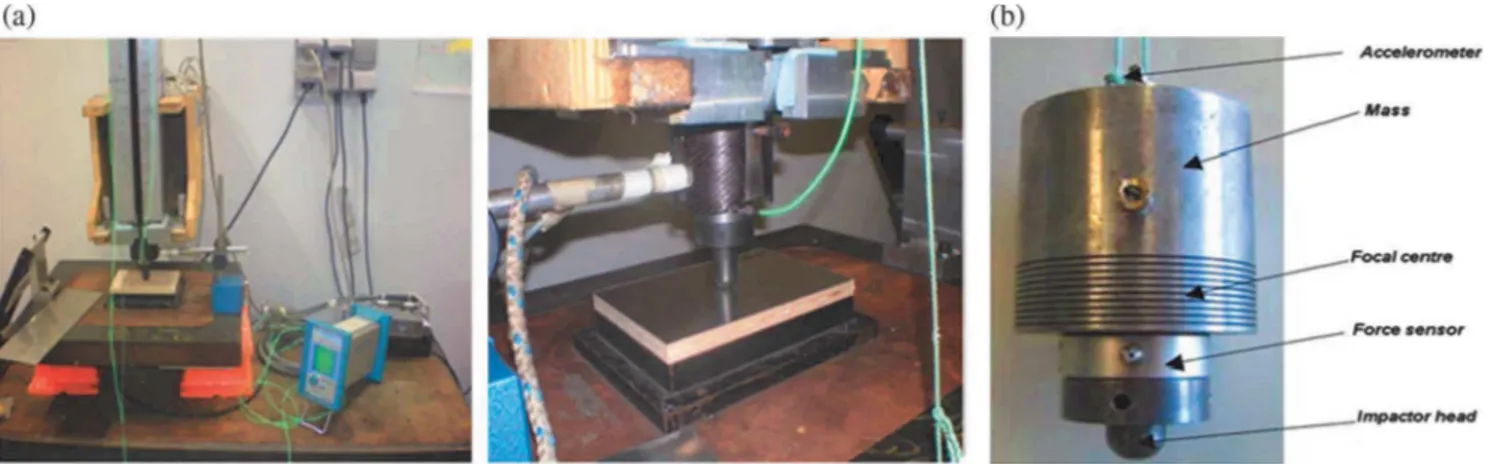
Impact tests were performed using a drop weight apparatus (Fig. 2) followed by tomography analysis. The principle of the falling weight is to drop an instrumented mass, guided in a tube, onto a sample plate held by a clamping window. In our test, the main components were:
•
A mass of 2.08 kg. This value was set so as to achieve the desired impact energy with speeds of up to 5 m/s;•
A load sensor located under the mass, to measure the force between the impactor and the specimen during the impact;•
A hemispherical impactor 16 mm in diameter;•
An optical sensor measuring the speed of the impactor immediately before impact;•
A support window, of internal dimensions 125 × 75 mm2, on which the specimen was positioned (standard specimen dimensions: 100 × 150 mm2). These dimensions were determined based onAirbus standards AITM 1-0010;
•
A clamping window having inner dimensions identical to those of the lower window (125 × 75 mm2) to hold the specimen during theimpact;
•
A kickback system to prevent multiple shocks on the specimen (same as in[24]).Fig. 1. Plywood A and B stacking. (For interpretation of the references to colour in this figure legend, the reader is referred to the web version of this article.)
Table 1
Specimens manufactured.
Core Skin Process Density Thickness (mm) Process specification
Plywood A – – 0.461 10 –
Plywood B – – 0.433 10 –
Plywood A Aluminum – 0.678 11 –
Plywood A Glass Vacuum bag molding - Prepreg 0.638 12 At 160 °C for 3 h
Carbon 0.569 At 90 °C for 30 min then at 125 °C for 1 h Plywood B Flax Thermo-compression - Prepreg 0.488 12 At 120 °C with pressure of 4 bar for 1 h
Carbon 0.614 At 90 °C for 30 min then at 120 °C for 1 h, all with pressure of 4 bar Glass 0.609 At 160 °C with pressure of 4 bar for 3 h
The load measured was not a real impact load, as a mass was present between the laminate and the sensor. The real impact load was calcu-lated according to the following expression:
= ⎡ ⎣⎢ − ⎤ ⎦⎥ − − F m m m F F ( ) ( ) real t t h f i( ) f i( 1)
where mt= mass of impactor, mh= mass of head, Ff= measured load,
Freal= real impact load Ff (filtered load) =(F( )i +F(i−1))/2 and Fi= measured load.
The filtered load is calculated on a sliding average of 40 points for an acquisition frequency of 200 kHz. The system for measuring the velocity of the impactor used an optical sensor (Laser), the output signal from which depended on the reflection of the emitted beam, and thus on the reflective surfaces engraved on the drop weight head (see
Fig. 1b). Initially, the acceleration was calculated using the following equation. = − − a F m m g ( ) i i t h
Knowing the distance and the time recorded by the laser between two grooves, it is easy to determine the initial velocity at impact. From the initial velocity at impact and the acceleration, instantaneous velo-city and displacement were calculated by numerical integration. The same numerical method was used to calculate the energy absorbed from a plot of displacement and real impact load. The results of a low ve-locity impact test at different impact energies, 5 J, 10 J and 15 J, cor-responding to energy levels generally encountered in the industry when tools fall onto on a floor, for example, were thoroughly investigated. We then considered the orientation of the top plies of the plywood core as a reference to distinguish the longitudinal and transverse directions. The
Fig. 2. (a) Drop-weight impact test set-up and aluminum wood specimen installed, (b) Impactor head. (For interpretation of the references to colour in this figure legend, the reader is referred to the web version of this article.)
Table 2
Test matrix of wood based sandwich structures for drop-weight impact test.
Materials Impact No. of samples Thickness of skin (mm) Area density (kg/m2) Density (kg/m3)
5 J 10 J 15 J
Plywood - A 1 1 1 3 – 4.6 461
Plywood - B 3 3 3 9 – 4.3 433
Plywood - A/Aluminum 3 3 3 9 0.5 7.5 678
Vacuum Molding Plywood - A/Glass 1 1 1 3 1 7.7 638
Plywood - A/Carbon 1 1 1 3 0.78 6.6 569
Thermo-compression Plywood - B/Flax 1 1 1 3 0.78 5.6 488
Plywood - B/Carbon 1 1 1 3 0.78 7.1 614
Plywood - B/Glass 1 1 1 3 1 7.3 609
Aramid HC/carbon and glass 1 1 1 3 0.89 2.4 233
Fig. 3. Failure modes of impacted plywood core at 10 J. (a) Plywood A, (b) Plywood B. (For interpretation of the references to colour in this figure legend, the reader is referred to the web version of this article.)
length and breadth directions were the same for all specimens. The test matrix for the impact test study is summarized inTable 2. The comprehensive results are available in ref [4]. The tomography analysis was performed using typical values given hereafter: Voltage 131 kV current 61 µA, no beam filter, Focal spot size: 8 µm (8 W), Image resolution: 1008 ∗ 1008, size of voxel: x = 5.01 µm and y = 5.01 µm.
3. Experimental results and discussion 3.1. Plywood structure
Firstly, it was observed that crack initiation always occurred in the plywood close to pre-existing damage in the plywood. These pre-ex-isting damages are due to the peeling cutting process used to obtain wood plies from the log. This process generates pre-cracks in the radial/ longitudinal plane that may propagate in the same direction or rotate to propagate in the tangential/longitudinal plane because of transverse shear[31]. A tomography analysis on damaged samples of plywood A and B is shown inFig. 3(a) & (b). In the case of plywood structures, a permanent indentation occurred at all energy levels through deforma-tion due to plasticity or fracture of wood ply. Maximum deformadeforma-tion occurred at the top ply due to crushing. Only one third of the sample was concerned at 5 J but permanent deformation occurred in up to one half of the sample for a 10 J impact test. For 15 J tests, perforation occurred and the impactor hangs in the plywood which creates the
second peak. In summary, for both plywoods (A and B), we identified fiber fracture, transverse shear, crushing, permanent indentation and deformation as predominant failure modes, with propagation to one half of the plywood core with increasing energy levels.
The impact response in terms of the energy absorbed at different energy levels (5 J, 10 J and 15 J) is presented inFig. 4a, b and c re-spectively. The influence of permanent indentation on absorbed energy is illustrated inFig. 4d andTable 3. In this table, the relative absorbed energy column represents the ratio between the absorbed energy and the measured impact energy in percent. The specific absorbed energy is obtained from the ratio of absorbed energy to the density. It is found that the force-displacement histories of plywood structures exhibit
Fig. 4. Force-displacement plot for plywood structure (a) 5 J, (b) 10 J, (c) 15 J, and (d) Ratio of Absorbed energy to indentation (J/mm). (For interpretation of the references to colour in this figure legend, the reader is referred to the web version of this article.)
Table 3
Absorbed energy and indentation results for Plywood A and B.
Materials Relative absorbed energy (%) Specific energy absorption (J) Depth of indentation (mm) 5 10 15 5 10 15 5 10 15 Plywood - A 51 81 99 5 19 32 1.56 1.87 – Plywood - B 67 70 98 8 16 35 1.65 2.30 – Aramid HC/carbon and glass 93 93 88 21 41 59 3.35 5.57 –
common trends, such as linear increase of force as the impactor contacts the panel, and a plateau that indicates crushing through radial com-pression of cell walls. Then, due to loss of stiffness caused by fiber fracture, transverse shear or debonding, the peak force starts to de-crease after attaining the peak value.
In terms of absorbed energy, the two plywood materials gave similar results with a slightly better performance for plywood A at higher en-ergy levels due to its slightly longer plateau. Also, permanent
indentation in plywood A was smaller than in plywood B due to its greater number of interfaces, which led to better transverse behavior. Both plywood structures showed comparable energy absorption cap-abilities and lower indentation when compared to our reference ma-terial of aramid honeycomb/carbon and glass skin. However, in terms of specific energy absorption, aramid honeycomb/carbon and glass skin yielded higher results due to its lower density. It is important to note that, at 15 J, all these structures were totally destroyed/perforated by the impactor (seeTable 3). The integrity of the structure was then compromised. Hence, the indentations, damage and integrity loss of the structure at higher energy levels would be unacceptable in most ap-plications.
3.2. Plywood structure with aluminum skin
With aluminum skins, a permanent indentation was observed for all impact energies due to the ductile property of this material and the smaller elastic spring back effect as shown inFig. 5. Delamination be-tween skin and core was not observed under the impactor but very slightly around it. In the case of 5 J impact, crushing, fiber fracture and transverse shear were observed in one third of the depth of the plywood core, i.e. down to the top okoume 0° ply. At 10 J, the same failure modes were observed on half the depth of the plywood core, down to the poplar 0° ply. At 15 J, the delamination and damage area increased
Fig. 5. Tomography images of impacted plywood with aluminum skin – Failure modes at 15 J. (For interpretation of the references to colour in this figure legend, the reader is referred to the web version of this article.)
Fig. 6. Force-displacement plot for Plywood A/Aluminum skin (a) 5 J, (b) 10 J, (c) 15 J, and (d) Ratio of absorbed energy to indentation (J/mm). Comparison with the reference sandwich panel impacted at same energy levels. (For interpretation of the references to colour in this figure legend, the reader is referred to the web version of this article.)
around the impactor. The same phenomenon as above, with maximum deformation, occurred down to two thirds of the depth of the plywood core, i.e. to the middle poplar 90° ply in plywood – A, as shown in
Fig. 5.
The force-displacement history of plywood with aluminum skin at different energy levels (5 J, 10 J and 15 J) is shown inFig. 6a, b and c and compared with our reference material of aramid honeycomb with carbon and glass skin. Globally, the shape shows that there is a little part of crushing (no plateau in the curve) for this sandwich. The me-chanism of absorption is mainly plasticity of the skins. We found that plywood structures with aluminum skin had energy absorption cap-abilities comparable to those of our reference material (seeFig. 6a and b andTable 4). However, in terms of specific energy absorption, aramid honeycomb/carbon and glass skin yielded higher results due to its low density. At higher energy levels, the rate of indentation increased ra-pidly, causing moderate indentation without perforation of the alu-minum skin, due to its ductile behavior, whereas aramid honeycomb was perforated and lost its structural integrity.
3.3. Plywood structure with composite skins 3.3.1. Failure patterns with carbon composite skins
With carbon fiber composite as shown in Fig. 7 a and b, small permanent indentation was observed under the impactor and top carbon skin, due to crushing of the core and elastic spring back of the skin. It also caused indentation and a damage area on the ply below the
top skin. The amount of damage and indentation area on the top skin were lower than in the wooden ply below the top skin. At 5 J, dela-mination was observed in the carbon fiber composite skins and at the interface between the core and the skin. Fiber fracture and crushing were observed in the top fifth of the plywood core. At 10 J, delamina-tion inside the skin and between the impacted skin and the core in-creased. Crushing, fiber fracture and deformation were observed in a quarter of the depth of the plywood core, down to the top okoume 0° ply. At 15 J, all the above failure modes spread into the top third of the plywood core, down to the top poplar 90° ply in plywood - B (see
Fig. 7b).
3.3.2. Failure pattern with glass composite skins
With glass fiber reinforced composite skins as shown inFig. 8a and b, the phenomena were quite different, with no delamination between the top skin and the core, thanks to their perfect adhesion. The dela-mination thus occurred at the ply below the top skin. Elastic spring back of the composite skin also caused damage at the poplar 90° ply and fiber fracture at the top okoume 0° ply below the skin, which led to higher deformation at the third ply from the top (poplar 90°) than at the second one. At 5 J, slight indentation and crushing occurred under the impactor, delamination and fiber fracture were observed in the glass fiber skin, and fiber fracture was observed in one tenth of the plywood
Table 4
Absorbed energy and indentation results for Plywood A with aluminum skins.
Materials Relative absorbed energy (%) Specific energy absorption (J) Depth of indentation (mm) 5 10 15 5 10 15 5 10 15 Plywood - A/Al 72 83 81 5 13 18 1.89 2.65 3.03 Aramid HC/carbon and glass 93 93 88 21 41 59 3.35 5.57 –
Fig. 7. Tomography images of impacted plywood with Carbon skins – Failure modes at 15 J, (a) plywood A, (b) plywood B. (For interpretation of the references to colour in this figure legend, the reader is referred to the web version of this article.)
Fig. 8. Tomography images of impacted plywood with glass skins – Failure modes at 15 J, (a) plywood A, (b) plywood B. (For interpretation of the references to colour in this figure legend, the reader is referred to the web version of this article.)
Fig. 9. Tomography images of impacted plywood with flax skins – Failure modes at 15 J, plywood B. (For interpretation of the references to colour in this figure legend, the reader is referred to the web version of this article.)
Fig. 10. Force displacement plot for Sandwich panels with plywood core and composite skins at 5 J (a), 10 J (b), 15 J (c). (For interpretation of the references to colour in this figure legend, the reader is referred to the web version of this article.)
Table 5
Absorbed energy and indentation results for plywood structures with composite skin.
Materials Relative absorbed energy (%) Specific energy absorption (J) Depth of indentation (mm)
5 10 15 5 10 15 5 10 15
Vacuum molding Plywood - A/Carbon 51 55 65 5 10 17 0.49 0.49 0.68
Plywood - A/Glass 58 75 70 5 13 17 0.13 0.38 0.47
Thermo-compression Plywood - B/Carbon 53 49 54 5 8 13 0.36 0.36 0.77
Plywood - B/Glass 54 68 75 5 11 20 0.13 0.16 0.24
Plywood - B/Flax 68 72 79 7 15 25 0.87 1.45 2.44
core, i.e. in a quarter of the cross section. In the case of 10 J, crushing occurred in a one quarter of the plywood core, delamination was ob-served between the skins and the core, but fiber and transverse shear fracture occurred in one quarter of the plywood core, down to the top okoume 90° ply. At 15 J, fiber fracture occurred in the composite skin, and transverse shear, crushing and maximum deformation occurred in one third of the plywood core, down to the top poplar 0° ply in plywood A (Fig. 8a & b).
3.3.3. Failure pattern with flax composite skins
Considering flax fiber reinforced composite skins, the damage modes were slightly different, as shown inFig. 9. At 5 J, delamination between the skin and the core, and moderate indentation occurred under the impactor due to elastic spring back of the composite skin. Fiber fracture was observed on the one tenth of the plywood core, down to the top okoume 0° ply, while crushing appeared on one third of the plywood core, down to the top poplar 90° ply. In the case of 10 J, de-lamination increased under the impactor, crushing was observed on 40% of the plywood core (down to the top poplar 90° ply) and fiber fracture appeared in the flax composite top skin. At 15 J, fiber fracture and indentation was found in one half of the depth of the plywood core, down to the middle okoume 0° ply in plywood B. Delamination in-creased and fiber fracture occurred in the flax skin.
3.3.4. Energy absorbed and indentation of plywood with composite skins Regarding energy absorption and indentation, the impact responses of plywood with composite skin at 5 J, 10 J and 15 J in terms of force vs displacement and ratio of absorbed energy to indentation are shown in
Fig. 10and also in Table 5. In the case of carbon skins, the higher stiffness of the skins and the lack of internal damages resulted in small indentation and the smallest absorbed energy as shown with shap shapes of the curves. This composite also resisted the highest impact load but with more delamination in the skin and extreme crushing of the plywood core due to its elastic spring back and the poor adhesion attained in the case of vacuum molding, where air can be trapped during vacuum creation. Regarding the glass fiber skins, absorbed en-ergy was comparable to that for flax, with also a smaller indentation than for carbon because of the higher strength of the skins and perfect adhesion obtained with the samples manufactured by thermo-com-pression as compared to plywood with carbon skin manufactured by both vacuum molding and thermo-compression. Despite a lower in-dentation than for the reference material, the ratio of absorbed energy to indentation (Fig. 11) was not much higher for the flax composite skin structure.
In summary, the plywood structure with glass fiber skins appears to provide a good compromise between absorbed energy (close to the flax skin material) and permanent indentation (seeTable 5). Regarding the influence of the process, very little effect was observed on the absorbed energy but a smaller permanent indentation appeared in the thermo-pressed case than in the vacuum molding ones. This was certainly due to better adhesion of the skins with this process.
3.4. Summary
The impact response of the eight different wood based sandwich structures and our reference materials are presented inFig. 12in terms of a force-displacement plot for the 15 J case only. In general, the initial slope of force-displacement varies with the skin materials, thus in-dicating variation in stiffness of the different wood based sandwich structures. As expected, the skin properties influence the impact be-havior of these sandwich structures even at lower displacement values. Concerning plywood structures, plywood A is found to yield slightly better results than plywood B in terms of absorbed energy and in-dentation, due to its longer plateau. Its higher number of interfaces causes better transverse behavior, which leads to smaller permanent indentation than in plywood B. Both plywood structures have parable energy absorption capabilities and lower indentation in com-parison to the reference material (seeTables 3–5). In terms of specific energy absorption, despite the good results of the materials under test, the reference material yields the highest results due to its low density. However, at 15 J, all these materials undergo perforation with heavy loss of structural integrity, which are incompatible with most applica-tions. The plywood also gives good results regarding specific energy absorption because of its low density.
For plywood structures with aluminum skins, compared to plywood structures alone, there is an absence of plateau and peak force oscilla-tion occurs due to the high strength and stiffness of the skin. This structure has comparable energy absorption and better resistance to indentation than the reference material but is not as good in terms of specific energy absorption, because of the high density of aluminum skin. Moreover, this structure results in a deeper indentation than in any of the other structures with composite skin, which can be un-desirable in some applications.
The ratios of absorbed energy to indentation are plotted in
Figs. 4(d),6(d) and11and are noted inTables 3–5. The specific energy
Fig. 12. Force-displacement plot for the different wood based sandwich structures at 15 J. (For interpretation of the references to colour in this figure legend, the reader is referred to the web version of this article.)
Fig. 11. Ratio of absorbed energy to indentation for plywood with composite skins (J/ mm). (For interpretation of the references to colour in this figure legend, the reader is referred to the web version of this article.)
absorptions at three energy levels for different sandwich structures are shown in Fig. 13. Two different processes, thermo-compression and vacuum molding with prepreg, were used to manufacture our panels of plywood structure with carbon/epoxy and glass/epoxy composite skins. In general, we found that the plywood with glass skin fabricated by the thermo-compression process had minimum defects, and better adhesion and structural integrity than that obtained by vacuum molding, as a result of the high operating temperature, the absence of trapped air, and the pressure used in the thermo-compression process.
In terms of energy absorption, carbon fiber reinforced composite shows somewhat weak results but with small indentation due to the greater stiffness of the skins. It also resists the highest impact load of all the plywood structures. However, it suffers from higher delamination in the skin and extreme crushing of the plywood core due to its elastic spring back effect and poor adhesion between skin and core, which results from the insufficient pressure used in the case of vacuum molding or the presence of trapped air in the case of thermo-com-pression.
With glass fiber reinforced composite skins, the behavior is quite different. The perfect adhesion and the spring back effect of the skin prevents delamination but decohesion occurs in the first ply of the plywood core. This results in an absorbed energy comparable to that observed with flax fibers, and smaller indentation than with carbon fibers because of the higher strength of the skins. Whatever the impact energy, this material is the best compromise between absorbed energy and indentation.
When flax fiber reinforcement is used in the skins, the composite behaves similarly to plywood with aluminum skins in terms of absorbed energy and specific energy absorption but shows smaller indentation as the plastic deformation is less than for aluminum. There is minimum delamination and debonding between skin and core due to the mod-erate elastic spring back effect and the better adhesion obtained through the thermo-compression process as compared to plywood with carbon skin fabricated by either the vacuum molding or the thermo-compression process.
Finally, regarding specific energy absorption (seeFig. 13), the re-ference material, aramid honeycomb with carbon and glass composite skins, yields the highest results because of its low density but undergoes perforation and loses its structural integrity for high energy impacts (15 J). In comparison, in the case of plywood with aluminum skin, crushing is transformed into indentation without perforation. Re-garding newly developed wood based sandwich structures; a very
interesting compromise can be obtained for flax skin structures thanks to their low weight and their high energy absorption.
4. Conclusions
In the nine materials tested, both the plywood structures demon-strated comparable energy absorption capabilities and lower indenta-tion in comparison to the reference material. However, plywood A yielded slightly better results than plywood B in terms of absorbed energy and indentation due to its longer plateau and its larger number of interfaces. Regarding plywood structures with skin, the plywood structure with glass fiber skin fabricated by the thermo-compression process seems to present a good compromise between absorbed energy (close to that of the material with flax reinforced skins) and permanent indentation (close to that of the structure with carbon reinforced skins). This results from its higher strength and the better adhesion provided by the thermo-compression process (noteworthy whatever the material considered). It also exhibits better results in terms of bonding or ad-hesion with the core as compared to plywood with carbon skin manu-factured by vacuum molding with application of high pressure. Following the plywood with glass skin, the plywood with flax skin, which is bio-based, offers a good compromise between energy absorp-tion and specific energy absorpabsorp-tion due to its lower density. In con-clusion, the development of these structures with plywood cores seems to be a good solution regarding impact concerns. These materials, which are more resistant, more functional and more environmentally friendly, could replace the ones currently used for cargo-bay floors in the aeronautics industry, for example. The only limitation remains the weight of these structures which is 2.5 times that of currently used materials. Nevertheless, for a floor intended for assembly on a final assembly line (i.e. outside a flying structure), this combination of properties associated with a 20 times lower cost seems to be a pro-mising solution for certain potential applications. Nevertheless, a pending question remains the recyclability of these materials. Prospects are also being considered for the development of new materials and their use in crash box applications in the automotive industry. References
[1] Zenkerts D. The handbook of sandwich construction. United Kingdom: Engineering Materials Advisory Services Ltd.; 1997.
[2] Bucci V, Corigliano P, Crupi V, Epasto G, Guglielmino E. Experimental investigation on Iroko wood used in shipbuilding. Proc Mech Eng C-J Mec 2017;231:128–39. Fig. 13. Specific energy absorption for the 8 configurations tested plus the reference one. (For interpretation of the references to colour in this figure legend, the reader is referred to the web version of this article.)
[3] Susainathan J, Eyma F, De Luycker E, Cantarel A, Castanié B. Manufacturing and quasi-static bending behavior of wood-based sandwich structures. Compos Struct 2017;182:487–504.
[4] Prakash John. Susainathan development and characterization of wood based eco-structure. PhD University of Toulouse; 2017.
[5] Abrate S, Castanié B, Rajapakse YDS. Dynamic failure of composite and sandwich structures. Springer; 2013.
[6] Balıkoglu F, Demircioglu TK, Inal O, Arslan N, Atas A. Compression after low ve-locity impact tests of marine sandwich composites: effect of intermediate wooden layers. Compos Struct 2018;183:636–42.
[7] Shin KB, Lee JY, Cho SH. An experimental study of low-velocity impact responses of sandwich panels for Korean low floor bus. Compos Struct 2008;84:228–40. [8] Vural M, Ravichandran G. Dynamic response and energy dissipation characteristics
of balsa wood: experiment and analysis. Int J Sol Struct 2003;40:2147–70. [9] Aminanda Y, Castanié B, Barrau JJ, Thevenet P. Experimental analysis and
mod-eling of the crushing of honeycomb cores. Appl Compos Mater 2005;12(3–4):213–7. [10] Castanié B, Bouvet C, Aminanda Y, Barrau JJ, Thevenet P. Modelling of low energy/ low velocity impact on Nomex honeycomb sandwich structures with metallic skins. Int J Impact Eng 2008;35:620–34.
[11] Castanié B, Aminanda Y, Bouvet C, Barrau JJ. Core crush criteria to determine the strength of sandwich composite structures subjected to compression after impact. Compos Struct 2008;86:243–50.
[12] Abrate S. Impact on composite structures. Cambridge University Press; 1998. [13] Heimbs S. Foldcore sandwich structures and their impact behaviour: an overview.
In: Abrate S, Castanié B, Rajapakse YDS, editors. Dynamic failure of composite and sandwich structures. Springer; 2013.
[14] Belingardi G, et al. Energy absorbing sacrificial structures made of composite ma-terials for vehicle crash design. In: Abrate S, Castanié B, Rajapakse YDS, editors. Dynamic failure of composite and sandwich structures. Springer; 2013. [15] Kolopp A, Rivallant S, Bouvet C. Experimental study of sandwich structures as
ar-mour against medium-velocity impacts. Int J Impact Eng 2013;61:24–35. [16] Ude AU, Ariffin AK, Azhari CH. Impact damage characterization in reinforced
woven natural silk/epoxy site face-sheet and sandwich foam and honeycomb. Int J Impact Eng 2013;58:31–8.
[17] Wang H, Ramakrishnan KR, Shankar K. Exp. study of the medium velocity impact
response of sandwich panels with different cores. Mater Design 2016;99:68–82. [18]Chai GB, Zhu S. A review of low-velocity impact on sandwich structures. J Mater
Des Appl 2011;225:207–30.
[19]Raju KS, Smith BL, Tomblin JS, Liew KH, Guarddon JC. Impact damage resistance and tolerance of honeycomb core sandwich panels. J. Comp Mater
2008;42:385–412.
[20]Toson B, Viot P, Pesqué JJ. Finite element modeling of Balsa wood structures under severe loadings. Eng Struct 2014;70:36–52.
[21]Atas C, Sevim C. The impact response of sandwich composites with cores of balsa wood and PVC foam. Compos Struct 2010;93:40–8.
[22]Hachemane B, Zitoune R, Bezzazi B, Bouvet C. Sandwich composites impact and indentation behaviour study. Compos Part B 2013;51:1–10.
[23]Petit S, Bouvet C, Bergerot A, Barrau JJ. Impact and compression after impact ex-perimental study of a composite laminate with a cork thermal shield. Compos Sci Technol 2007;67:3286–99.
[24] Mezeix L, Dols S, Bouvet C, Castanié B, Giavarini JP, Hongkarnjanakul N. Experimental analysis of impact and post-impact behaviour of inserts in Carbon sandwich structures. J. Sand Struct Mater, on line,http://dx.doi.org/10.1177/ 1099636216687582.
[25]Abdalsalm SO. Impact damage analysis of balsa wood sandwich composites Thesis USA: Wayne state university; 2013.
[26]Wang H, Ramakrishnan KR, Shankar K. Experimental study of the medium velocity impact response of sandwich panels with different cores. Mater Des 2016;99:68–82. [27]Li W, Van den Bulcke J, Mannes D, Lehmann E, De Win I, Dierick M, et al. Impact of
internal structure on water-resistance of plywood studied using neutron radio-graphy and X-ray tomoradio-graphy. Construct Build Mater 2014;73:171–9.
[28]Paris JL, Kamke FA. Quantitative wood-adhesive penetration with X-ray computed tomography. Int J Adhesion Adhesives 2015;61:71–80.
[29]Corigliano P, Crupi V, Epasto G, Guglielmino E, Maugeri N, Marinò A. Experimental and theoretical analyses of Iroko wood laminates. Compos Part B 2017;112:251–64. [30]Crupi V, Epasto G, Guglielmino E. Internal damage investigation of composites
subjected to low-velocity impact. Exp Tech 2016;40(2):555–68.
[31]Denaud LE, Bleron L, Eyma F, Marchal R. Wood peeling process monitoring: a comparison of signal processing method to estimate veneer average lathe check frequency. Eur J Wood Wood Prod 2012;70(1):253–61.