Science Arts & Métiers (SAM)
is an open access repository that collects the work of Arts et Métiers Institute of Technology researchers and makes it freely available over the web where possible.
This is an author-deposited version published in: https://sam.ensam.eu
Handle ID: .http://hdl.handle.net/10985/9488
To cite this version :
JeanPierre MASSAT, Etienne BALMES, JeanPhilippe BIANCHI, Guido VAN KALSBEEK -OSCAR Statement of Methods - Vehicle System Dynamics - Vol. 53, n°3, p.370-379 - 2015
Any correspondence concerning this service should be sent to the repository Administrator : [email protected]
Paper title: OSCAR Statement of Methods
Jean-Pierre Massat1, Etienne Balmes2, Jean-Philippe Bianchi2, Guido Van Kalsbeek1
1
SNCF, Engineering department of Infrastructure, Paris, France
2
Arts et Metiers ParisTech & SDTools, Paris, France
E-mail corresponding author: [email protected] Address for correspondence:
Jean-Pierre MASSAT
6, avenue François Mitterrand 93574 La Plaine Saint Denis CEDEX Tel : +33 (0)1 41 62 00 29
Abstract
OSCAR is the pantograph catenary dynamic software developed by SNCF since 2004. A three-dimensional Finite Element mesh allows the modelling of any catenary type: AC or DC designs, conventional or high speed lines. It is representative of the real overhead line geometry, with contact wire irregularities, staggered alignment of the contact wire (CW), dropper spacing, wire tension, etc. Non-linearities, such as slackening of droppers and unilateral contact between the pantograph and the contact wire, are taken into account. Several pantograph models can be used, with a complexity level growing from the three lumped mass model to the multi-body (MB) model. In the second case, a cosimulation between the FEM catenary and the MB pantograph models has been developed. Industrial features for pre and post-treatments were developed to increase robustness of results and optimize computation time. Recent developments include volume meshing of the contact wire for stress computation or statistical analysis and lead to new fields of studies such as fatigue failure or design optimization. OSCAR was fully validated against inline measurements for its different AC and DC catenary models as well as its different pantograph models (with independent strips for instance) and has continuously been certified against EN50318 since 2008.
Introduction
Train operators seek to augment the running speed, increase capacity and improve regularity. Infrastructure managers have to guarantee installations reliability and drastically reduce maintenance costs. Rolling stock has to become interoperable in order to enable railway development, while fulfilling European laws.
Inline tests are mandatory to reduce the number of incidents, to assess a new pantograph design, or to optimize operational conditions. But besides accounting for a major risk in projects because of the lateness with which they can be carried out, they also become very costly and are in conflict with commercial use of railway network. Simulation tools can support and shorten these processes by anticipating and complementing inline tests as well as by studying a possible compromise between different above mentioned challenges and are therefore increasingly used.
OSCAR (Outil de Simulation du CAptage pour la Reconnaissance des défauts) is the fulfilment of almost 30 years of research and development activities on pantograph-catenary interaction simulation carried out at SNCF. The first model, developed in 1984, was simply based on 2D FEM catenary and linear three lumped-mass models of pantograph. Then, a first multibody pantograph model was included in 1998[1]. In 2004, totally new software named OSCAR was written. A generic 3D finite element model, where any element can be used, allows the representation of a wide variety of catenaries: AC or DC design, with one or more contact wires, with different carrying structures (rigid, from zero to several messenger cables, with or without stitch wire), with a
fixed or suspended registration tube, etc. The only constraint is that the contact wire should use pre-stressed Euler-Bernoulli beams [2][3]. In practice the messenger wire is modelled using the same type of elements. The main non-linearities considered in the catenary are contact with the pantograph contact strips and dropper slackening [4].
The minimum requirement on contact wire, lets the software go beyond basic simulations by taking into account perturbed situations and singularities. Applications consequently range from design optimizationin plain line track, to the study of specific arrangements like overlap sections or road over-bridges.
Many pantograph types are available based on linear and non-linear lumped-mass models. In 2010, a new feature was introduced to increase accuracy of rolling stock description. Built from CAD, the multi-body pantograph models [1][5] open new application fields such as the assessment of geometrical compatibility between pantograph and catenary.
A new plug-in is currently under development for the evaluation of 3D stress fields in the contact wire. Coupled with an iterative contact wire wear procedure, maintenance issues such as fatigue can be addressed.
A special effort was paid in the development of OSCAR to optimize performance and allow industrial use. SNCF takes advantage of this powerful and accurate software to carry out studies and develop its expertise in:
designing catenary and pantograph systems;
preparing the certification of new systems, drastically decreasing costs; and assessing new maintenance strategies.
OSCAR is regularly used in industrial cases. One illustrative case was the preparation of the world rail speed record where a speed of 574.8 km/h was reached in April 2007 by SNCF, RFF and Alstom. Speed records are challenging because the pantograph-catenary dynamics reaches a physical limit named "catenary barrier" where train speed becomes close to the wave propagation speed in the catenary, thus leading to high vertical displacements provoking severe contact losses. The theoretical maximum speed computed by OSCAR, to respect a maximum uplift of 30 cm at steady arms, was very close to the final test at 580km/h..
More recently, a European project named PantoTRAIN addressed virtual certification of rolling stock. Simulation tools were used to establish a procedure in order to reduce inline tests during a rolling stock admission. This method was tested and approved by a blind test validation.
OSCAR is developed by SNCF in cooperation with SDTools. The programming language is MATLAB and Structural Dynamic Toolbox (SDT©) developed by SDTools, which include finite element and time simulation capabilities. Critical FE modules are rewritten in C++ to optimize computation time. The software is either used on personal computers or on servers for large parametric studies. It is supported on Windows and Linux environments.
Many pre-processing and post-processing facilities are available to suit daily industrial use. For example:
Excel input files for pantograph and catenary data; automatic computation of criteria from standards; automatic report generation; and
automatic procedure to assess numerical convergence.
2. Methods as applied in the benchmark
Instructions given by the benchmark statement were entirely followed in simulations performed with OSCAR. This section describes how these instructions were implemented.
The catenary model uses a periodic model of 21 spans, representing a total length of 1155 m (see Figure 1), which is two times longer than the 10 central spans required by instructions. It was built to guarantee that dynamic perturbations involved by pantograph start are stabilized before entering the central 10 spans and boundary conditions do not impact dynamics because of wave reflections.
Figure 1 – Benchmark simulation case in OSCAR
Erreur ! Source du renvoi introuvable. gives the number of elements used in the model for each
part of the catenary: contact wire (CW), messenger wire (MW), droppers, steady arms and claws. The full model represents 33114 degrees of freedom.
Table 1 – Figures about catenary model used for the benchmark.
Finite element type Number of elements
Contact wire Pre-tensioned beam 4240
Messenger wire Pre-tensioned beam 1266
Droppers Bar 189
Steady arms Bar 20
claws Mass 398
Pantograph Mass 3
Full model 6116
2.1 Catenary Model
OSCAR handles a wide variety of overhead line geometries which can only be achieved by the Finite Element Method (FEM). The overhead line model is fully three-dimensional, including stagger.
Two different catenary models were built to follow the benchmark instructions: one 2D model and one 3D model as illustrated in Figure 2. The 2D model is a 3D model without stagger. Therefore, steady arms are kept in the 2D model as shown in Figure 2.
The CW and MW meshes are refined to reduce numerical discrepancy, especially due to element passing excited by the moving load. The CW mesh is meshed with zero sag.
The contact wire and the messenger wire use pre-tensioned beam finite elements. These elements are loaded through their modes with three forces (axial and two orthogonal) and three moments (torsion and two bending) and use Hermite shape functions. The element combines a classical Euler-Bernoulli beam formulation with an additional geometric stiffening associated with the axial tension which is necessary to obtain the proper catenary geometry and local stiffness.
Two kinds of catenary non-linearities are considered in OSCAR for this benchmark: dropper slackening and a non-linear static state. Dropper slackening is one of the most important features of pantograph-catenary dynamics software. Bar elements used to model droppers are not refined and only one element links the contact wire to the messenger wire. Specific loads are computed and added to dynamic loads in order to compensate the compressive stress of each dropper.
The calculation of the catenary static state is highly non-linear because of large displacements provoked by gravity and cable elongation. As a consequence, the stiffness of the structure varies according to the mechanical tension applied at the cable ends.
Figure 2 – 2D and 3D catenary models used for benchmark.
2.2 Pantograph model
The pantograph model used in OSCAR is a three lumped mass model as described in the benchmark instructions. It is a linear description of three first vertical dynamic modes of the pantograph. This simplified model is built with mass elements, springs (stiffness) and dampers. A constant speed is applied during the whole simulation case. In the same way, a constant static load is applied during the whole simulation.
2.3 Model of pantograph-catenary contact
OSCAR uses a penalty method for pantograph-catenary contact model. It consists in introducing a contact stiffness KContact and a possible damper CContact between the pantograph and the contact wire.
Figure 3 – Contact scheme used by OSCAR
The distance between the pantograph mass and the catenary contact wire is defined by
= − –
where CWRadius depends on the wear (zero value in the benchmark) and is computed using
Hermite shape functions and the corresponding modal displacement and rotation The contact force follows a non-linear law allowing contact losses to occur:
2D 3D Front view Top view 3D isometric view
= − ∙ + _ ∙ ̇ < 0
= 0 > 0
This load is distributed on the two nodes of the finite element in contact with the upper pantograph mass using appropriate shape functions.
2.4 Numerical integration procedure
The numerical integration procedure is an implicit Newmark scheme [3][6]. This solver uses a classical prediction followed by correction loops on displacement, velocity and acceleration with exit based on a threshold on the norm of the residual error on the equilibrium. The main benefit of the implicit method is that computation time step can be relatively high (up to 10-3s) thus giving a good efficiency.
2.5 Initialisation of the problem (steady state configuration of the catenary)
The steady state configuration of the catenary is a key factor in the quality of pantograph-catenary dynamic interaction especially for comparison with inline measurements. Indeed, the pantograph is a moving load running on a flexible discretized geometry that is highly dependent on the gravity and mechanical tension. In OSCAR two methods were developed to compute this static state:
The mesh is built using geometrical description of each component: dropper lengths, dropper and mast positions, claw masses, etc. Gravity and mechanical tension are applied iteratively to obtain the static state. This method aims at assessing the sag of the catenary. The contact wire position at each dropper location is imposed, either from external data like
the benchmark or from inline measurements of contact wire height. The dropper lengths are adjusted with an iterative method to obtain the equilibrium state of the catenary system. This method is used to identify the dropper length by minimizing the dropper tension error
The static computation problem is non-linear because of possible dropper slackening and more importantly because of the relation between geometry and the exact tension in each wire, which is important for fully 3D geometries. An iterative solver is thus set up, where the stiffness matrix based on actual tension is reassembled at each loading step. The second method was used to obtain the contact wire height at each dropper position imposed in the benchmark instructions.
The static position is used to initialize the dynamic computation. The stiffness matrix used in dynamics comes from the converged static state and remains constant during the time simulation because of the small displacement hypothesis.
Finally, the initialization process is not realistic because the pantograph speed increases from 0 km/h to the assessed running speed between time steps t0 and t1, contrary to the real conditions
which are more progressive. This abrupt starting is damped along the first catenary spans. Nevertheless, this transitional area has to be identified and removed from final analyses. In OSCAR, this study is systematically carried out and post-processing is only applied in an area where dynamics are stabilized.
3. Additional methods available
OSCAR was initially developed to assess pantograph-catenary dynamics. Pantograph models are lumped mass models, including non-linearities like bump-stops or friction for instance, with one or multiple flexible and tilting contact strips, as shown on Figure 4.
Any kind of transition in the catenary can be taken into account. Examples that have been considered are section overlaps, where the pantograph switches between two contact wires within a short period where it is in contact with both wires, level crossings, over-bridges, neutral section systems and so on. One of the major issues for the algorithms is to detect the contact on each wire, taking into account the wire staggers. In the same way, OSCAR manages DC catenaries (compound or not) including several contact and several messenger wires.
Figure 4 – Three lumped mass model of pantograph and overlap section
One of the first uses of OSCAR was a study of the effect of catenary defects on current collection, in order to optimize maintenance by understanding their consequences. An identification of the signatures of each defect allowed their automatic detection by an instrumented pantograph. For that purpose, missing droppers, junction claws, tension variations were introduced in simulation cases [7].
Simulation expectations have evolved over the past five years especially to address maintenance and interoperability topics. These objectives led to three main developments: a cosimulation process with a multibody pantograph, a volume mesh of the contact wire to compute 3D stress fields and a probabilistic approach to introduce variability and uncertainties in simulation studies.
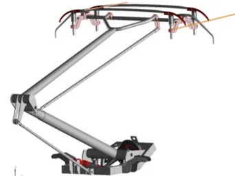
A cosimulation was designed between the well validated catenary model and a multibody pantograph model [8] which is built from a CAD file (see Figure 5). This detailed geometrical description of the pantograph is necessary to study compatibility with infrastructure or to design new components.
The model can be either rigid, partially or fully flexible. Impact of the flexibility of each body can separately be evaluated. In the same way, bushing joints are used to take into account clearance and flexibility in joints. Laboratory tests are used to adjust the model through an experimental modal analysis (EMA).
Moreover, the multibody model can be actuated by a pneumatic system including its control system. To do so, data is exchanged between the mechanical workspace and the pneumatic one at each time step. The French pantograph illustrated on Figure 5 is deployed by an air spring whose pressure supply is controlled as a function of the train speed with an open and a closed loop.
The cosimulation procedure was optimized to guarantee the efficiency of the simulation tool. The multibody software computes the contact force between the contact wire and the pantograph head. This data is then sent to the FE catenary through the random access memory, which computes the contact wire displacements and so on.
Figure 5 illustrates a typical use of pantograph multibody model in an overhead crossing. A contact wire coming from a side track enters in contact with the pantograph horns. These horns are designed to guide the contact wire on the top of the contact strips, but in some critical conditions the contact wire may slide under the bow and break the pantograph. This detailed pantograph geometry makes it possible to identify these critical cases and propose enhancements of the system.
Figure 5 – Multibody pantograph: overhead crossing simulation
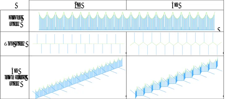
Fracture by fatigue is one of the most critical failures which may occur on the railway network because it is almost unpredictable and induces huge traffic disruptions [9]. A plug-in was developed in OSCAR to include a volume model of a part of the contact wire (typically 2 or 3 meters long) and connected elements (such as claws, as illustrated in the right of Figure 6) in a beam catenary mesh. The volume mesh is used in static computations but its use in dynamic computations would lead to prohibitive times as well as irregularities in the contact force around the 1D-3D transition. Therefore dynamics are obtained through an adapted beam model. A static expansion [11] is used to recover 3D motion and stress fields in order to study fatigue failure of the contact wire through the Dang Van criteria [10] and estimate lifetime before crack initiation. In parallel, as shown on Figure 6, an iterative wear model is used to identify the first failure mode [12].
Figure 6 – 3D model of contact wire for fatigue study (left: CW mesh, middle: worn CW with axial stress colour map, right: 1D-3D mesh connection).
Finally, a probabilistic approach is under implementation. Until recently, only a deterministic approach was considered, but the lack of reproducibility of inline measurements was not correctly represented in simulation tools. Considering a perturbed catenary geometry with a non-constant wear along it and with external forces like aerodynamics, OSCAR outputs can be used to optimize either the design or the maintenance tolerance because a wide range of operational conditions are covered.
This functionality will be particularly meaningful for virtual certification process: the PantoTRAIN project [18] shows that variability and uncertainties have to be considered to be representative from inline tests.
4. Validation of the software
OSCAR has been certified by an independent body since 2008 with respect to the EN50318 standards [13]. This certification was renewed in 2013 for the latest version of OSCAR.
It was validated against another software which consists in a mono-dimensional analytical model (not presented in this benchmark) which uses displacement decomposition in sine series [3]. This method being continuous, it is very useful to validate results from Finite Element simulations which
can present numerical discontinuities [4][15][16]. This comparison permitted to define the optimal FE number for instance.
It was validated against inline measurements, at high speeds [17] and at conventional speeds, for different catenary designs (light and compound catenaries) and for several pantograph models. It was also validated with catenary defects. The very good agreement allows generating numerical dynamic signatures of catenary defects [7].
OSCAR was used in two European Projects EUROPAC and PantoTRAIN. In PantoTRAIN, simulation results were compared to inline measurements [17]. Several European high speed pantograph-catenary couples were modelled. For each one, the results showed a very good agreement with inline measurements, below 1% of error in the best cases and less than 10% in the worst cases [18] against EN50367 standard criteria [14] when the EN50318 standard requires a maximum error of ±20%. These good results were obtained either with or without overlap sections (transitions).
Finally, it was validated against measurement for single and multiple unit configurations. Recently a blind test was performed against measurements. Simulations were performed before tests and were compared at the end. OSCAR simulation results were again found to be very predictive.
5. Considerations about results
The numerical stage of the benchmark was defined to assess the spread between existing pantograph-catenary software. The benchmark case is fully defined, addresses problems encountered in pantograph catenary simulation and allows all software to perform the simulation by defining progressive complexity levels. Nevertheless, three remarks can be made on the results. First, the distance between the starting point of the pantograph and the central spans area defined for analysis can explain some differences between results, especially for the vertical displacement of the steady arm. Indeed, movements observed before the pantograph arrival are due to wave propagation.
Second, the transition period corresponding to the brutal start of the pantograph should be assessed, because it is highly dependent on the initialization procedure of each software. A model including two sections and an overlap area could solve this problem, with a first catenary section dedicated to this transition period and a second catenary section used for analyses. Nevertheless some software may not be able to follow this procedure.
Third, the catenary damping model is a key factor in the dynamic behaviour. Differences of results may be partially explained by the damping model which differs from one software to another. For example, in OSCAR alone, there are four different damping models: proportional (used in this benchmark to follow instructions), piecewise proportional (the most commonly used in studies), modal (the most physical model) and localised (generally coupled with one of the first two models) [19].
6. Conclusions
The benchmark instructions defined a purely numerical case to study the spread between software simulating dynamic pantograph-catenary interaction.
The FE software OSCAR was used to follow these instructions, using successively a 2D and 3D model. Static and dynamic results were performed. In both cases, it shows behaviour similar to that of other software.
OSCAR is used to capitalize more than 30 years of experience at SNCF. It has been validated against measurement during all development stages and been certified against the EN50318 standard. More complex cases than those defined in the benchmark are more representative of real
operation conditions. For instance, overlap areas generally need to be considered. In the last five year, major OSCAR developments were related to multibody pantographs, volume models of the contact wire for fatigue failure studies.
References
[1] F. Labergri, Modélisation du comportement dynamique du système pantographe-caténaire, doctoral thesis 2007.
[2] A.Collina and S. Bruni. Numerical simulation of pantograph-overhead equipment interaction. Vehicle System Dynamics, 38:261–291, 2002.
[3] J.-P.Massat, Modélisation du comportement dynamique du couple pantographe-caténaire. Application à la détection de défauts dans la caténaire, doctoral thesis 2007.
[4] A. Bobillot, J.-P. Massat, J.-P. Mentel, Design of pantograph-catenary systems by simulation, The Seventh International Conference on Engineering Computational Technology, 14-17 September 2010, Valencia, Spain.
[5] F. Grases-Rauter, Pantograph-Catenary Interaction using Flexible Multibody Dynamics Methodology, doctoral thesis 2009.
[6] Michel Géradinand Daniel Rixen. Théorie des vibrations - Application à la dynamique desstructures. Masson - 2eme édition, 1996.
[7] J.-P. Massat, A. Bobillot, J.-P.Lainé, Robust Methods for Detecting Defects in Overhead Contact Line Based on Simulation Results, III ECCOMAS Conference 2006, Lisbon, Portugal, 5–8 June, 2006
[8] J.-P. Massat, C. Laurent, J.-P. Bianchi, E. Balmes, Pantograph catenary dynamic optimisation based on advanced multibody and finite element co-simulation tools, VSD volume 52, supplement 1, 2014, doi:10.1080/00423114.2014.898780
[9] A. Sugahara, Preventing Fatigue Breakage of Contact Wires, Railway Technology Avalanche No. 24, September 19, 2008.
[10] K. Dang Van and I. Papadoupoulos, Eds., High-Cycle Metal Fatigue in the Context of Mechanical Design, CISM Courses and Lectures, No.392, Springer-Verglas, 1999.
[11] E. Balmes, Sensors, Degrees of Freedom, and Generalized Modeshape Expansion Methods, International Modal Analysis Conference, 1999.
[12] M.L. Nguyen-Tajan, S.-H. Mai, J.-P. Massat, S. Avronsart, J. Banting. J.-P. Bianchi, H. Maitournam, Fatigue crack initiation risk analysis and crack propagation modelling in the catenary contact wire of high speed lines, In: Proceedings of the World Congress of Railway Research, 2013.
[13] EN 50318 standard, Railway applications – Current collection systems – Validation of simulation of the dynamic interaction between pantograph and overhead contact line. 2002 [14] EN 50367 standard, Railway applications – Current collection systems – Technical criteria
for the interaction between pantograph and overhead line, 2006.
[15] J.-P.Massat, J.-P.Lainé, A. Bobillot, Pantograph-Catenary Dynamic Simulation. Proceedings of the IAVSD conference, 2004.
[16] W. Zhang, G. Mei, X. Wu, and Z. Shen. Hybrid simulation of dynamics for the pantograph-catenary system. Vehicle System Dynamics, 38:393–414, 2002.
[17] J.-P. Massat, C. Laurent, T.M.L. Nguyen-Tajan, A. Facchinetti and S. Bruni, Simulation tools for virtual homologation of Pantograph, Railways 2012 Conference, Las Palmas de Gran Canaria, Spain, 18-20 April 2012
[18] PantoTRAIN EU research project, Deliverable D6.3, Proposals for integrations to existing standards and homologation processes and their assessment for safety, quality and practical feasibility, www.triotrain.eu, 2012.
[19] J.-P. Bianchi, E. Balmès, A. Bobillot, Using modal damping for full model transient analysis. Application to pantograph/catenary vibration, ISMA2010 Noise and Vibration Engineering conference 2010.