Université de MontréaÏ
Migrating Legacy System towards Object Technology
par
Lei
Wu
Département d’informatique et de recherche opérationnelle
Faculté des arts et des sciences
Thèse présentée à la Faculté des études supérieures
en vue de l’obtention du grade de
Philosophie Doctor (Ph.D.)
en informatique
août, 2005
(
I-r)
Unîversité
de Montréal
Direction des bibliothèques
AVIS
L’auteur e autorisé l’Université de Montréal à reproduire et diffuser, en totalité ou en partie, par quelque moyen que ce soit et sur quelque support que ce soit, et exclusivement à des fins non lucratives d’enseignement et de recherche, des copies de ce mémoire ou de cette thèse.
L’auteur et les coauteurs le cas échéant conservent la propriété du droit d’auteur et des droits moraux qui protègent ce document. Ni la thèse ou le mémoire, ni des extraits substantiels de ce document, ne doivent être imprimés ou autrement reproduits sans l’autorisation de l’auteur.
Afin de se conformer à la Loi canadienne sur la protection des
renseignements personnels, quelques formulaires secondaires, coordonnées ou signatures intégrées au texte ont pu être enlevés de ce document. Bien que cela ait pu affecter la pagination, il n’y a aucun contenu manquant. NOTICE
The author of this thesis or dissertation has granted a nonexclusive license allowing Université de Montréal to reproduce and publish the document, in
part or in whole, and in any format, solely for noncommercial educational and
research purposes.
The author and co-authors if applicable retain copyright ownership and moral
rights in this document. Neither the whole thesis or dissertation, nor
substantial extracts from it, may be printed or otherwise reproduced without the author’s permission.
In compliance with the Canadian Privacy Act some supporting forms, contact information or signatures may have been removed from the document. While this may affect the document page count, t does flot represent any Ioss of content from the document.
Université de Montréal
faculté des études supérieures
Celle thèse intitulée
Migrating Legacy System towards Object Teclinology
présentée par:
Lei Wu
a
été évaluée par
un jury composé des personnes suivantes
Pierre Poulin
(président-rapporteur et représentantdu doyen de la FES)
Houari A. Sahraoui
(directeur de recherche)Petko Valtchev
(codirecteur)Julie Vachon
(membre du jury)Hafedh Miii
(examinateur externe)Sommaire
Durant la dernière décennie, les technologies orientées objet (00) ont connu un grand succès dans le développement logiciel. Le paradigme 00 facilite la conception et la compréhension de systèmes avec dissimulation et abstraction de l’information. Il est aussi muni d’une variété de dispositifs dont le développement et la maintenance de logiciel tirent grand profit. Comme résultat, les logiciels construits autour du paradigme 00 sont en général plus réutilisables et plus faciles à maintenir. D’un autre côté, de nos jours, plusieurs logiciels hérités et vitaux qui ont été développés avant l’apparition de la technologie objet sont sévèrement confrontés à la difficile question de maintenance. La plupart de ces systèmes hérités subissent des changements continues pour satisfaire les nouveaux besoins. Ils présentent un haut niveau d’entropie: les systèmes hérités deviennent mal structurés, pauvrement documentés et faiblement modélisés. Afin de préserver la haute valeur économique de ces systèmes et du coup leur permettre de bénéficier des avantages de la technologie objet, leur migration aux technologies 00 a été préconisée comme l’une des meilleures pratiques.
Bien que des méthodes de réingénierie qui visent la migration des systèmes hérités à la technologie 00 aient été d’abord étudiées au début des années quatre-vingt-dix, la grande partie des travaux de recherche se concentrent seulement sur les techniques d’obtention des modèles objets du code du système hérité sans considérer en entier le processus de migration.
Pour résoudre ce problème, cette thèse présente un cadre de réingénierie pour aborder la problématique de migration des systèmes hérités. Nous avons exploré les éléments pertinents de l’évolution et de la réingénierie de ces systèmes, et avons développé un cadre d’application complet adapté à leur migration. Nous avons développé des outils et des techniques pour réduire la complexité et pour assurer la qualité du processus de migration. Ceux-ci incluent le développement de l’analyse des systèmes hérités, de la décomposition des logiciels, de la restauration de la conception, du modèle de restructuration de l’architecture, du modèle incrémental de migration et de
11
l’environnement de support. Les résultats expérimentaux illustrent l’efficacité et l’utilité de notre approche de migration.
Mots clés: réingénierie, rétro conception, systèmes hérités, migration, orienté objet, restructuration de l’architecture, modèle de migration.
111
Abstract
During the past decade, object-oriented technoÏogy has gained great success in software system development. it facilitates the design and understanding of a system with information hiding and abstraction. it also provides a variety of desirable features that greatly benefit to the practice of software development and maintenance. As a resuit, software systems implernented with the 00 paradigm are in general more reusable and more maintainable. On the other hand, nowadays, many vital legacy software systems that were developed before the appearance of object technology are chronicalty facing the difficuit question of maintenance. Most of these systems have undergone continuous changes to meet the evolution needs. They present a high level of entropy: the systems have becorne ill-structured, poorly documented, and weakly rnodeled. To preserve the bigh economic value ofthose legacy systems and meanwhile make them benefit from the advantages ofobject technology, migrating legacy systems towards object technology has been advocated as one of the best practices.
Although reengineering methods that aim at migrating legacy systems to object technology have first been studied in the nineties, most ofthe research work focuses only on the techniques to elicit object models from legacy code without considering the whole migration process.
To solve this problem, this thesis presents a reengineering framework to tackie the legacy migration issue as a whole. We have explored the pertinent issues concerning Iegacy system evolution and reengineering, and have developed a comprehensive framework to accommodate legacy system migration. We have developed tools and techniques to reduce the complexity and ensure the quality of the migration process. These include the developrnent of legacy system analysis, software decomposition design recovery, re-architecturing, incremental migration model, and supporting environment. The experimental results illustrate the effectiveness and usefulness of our legacy system migration approach.
iv
Keywords: reverse engineering, re-engineering, legacy system migration, object
V
Acknowledgcments
I would like to sincerely thank my research director professor Houari Sahraoui, for his profound supervision and continuai support during ail these years. Ris valuabÏe guidance and pertinent advice have greatly helped me to conduct this research.
My earnest thanks would also go to my research co-director, professor Petko Valtchev. I genuinely thank him for his intensive heÏp on rny rescarch, the nurnerous discussions on my research papers, and the rigorous reviewing of rny thesis.
My thanks also go to Professor Yann-GaI Guéhéneuc for rnany interesting discussions on the topics related to rny thesis.
I thank rny parents, rny wife, and rny sister for their unconditional support and consistent heip for many years.
vi
Table of Contents
Chapter 1. Introduction 1 1.1 Motivation 2 1.2 Problem Statement 3 1.2.1 Software Evolution 4 1.2.2 LegacyDilemma 4 1.2.3 Direction 5 1.3 Thesis Objectives 6 1.4 Thesis Overview 7Chapter 2. State of the Art: Literature Review 10
2.1 Reverse Engineering 10 2.1.1 ProgramAnalysis 11 2. 1 .2 Software Comprehension 12 2.1.3 Software Visualization 14 2.1.4 Architecture Recovery 15 2.2 Re-engineering 17 2.2.1 Restructuring 17 2.2.2 Software re-engineering 18
2.3 Migration towards Object Technology 21
2.3.1 Migration fomis 22
2.3.2 COREM Approach 23
2.3.3 ERCOLE approach 25
2.3.4 Legacy wrapping 27
2.4 Legacy Code Modeling Techniques 30
2.4.1 Similarity Clustenng 31
2.4.2 Concept Analysis 33
2.4.3 Global Variables and Types 33
vii
2.4.5 Discussion. 35
Chapter 3. Migration Methodology Framework 37
3.1 Overview 37
3.2 Ideal Migration Process Mode! 38
3.3 Practical Migration Process Model 41
3.4 lntegrated Migration Support Environment 44
3.5 Summary 45
Chapter 4. Legacy System Analysis 46
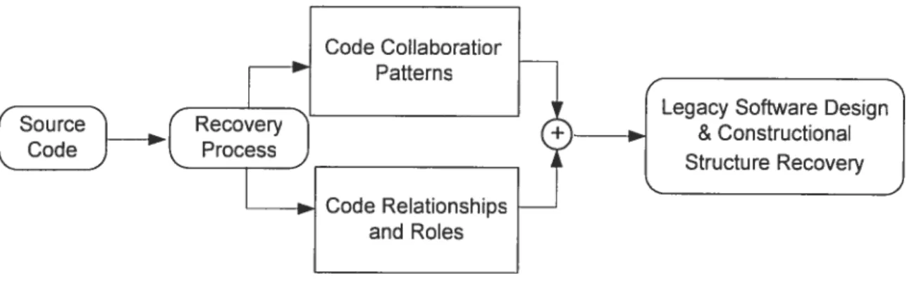
4.1 Source Code Collaboration Pattern and Role Analysis 46
4.1.1 Approach Introduction 47
4.1.2 General Concepts 48
4.1.3 Co!Iaboration Pattem and Role Recoveiy Approach 50
4.1.4 Automation with Di’namk-Ancilï:er 53
4. 1 .5 Recording System Functiona! ity Scenario 59
4. 1.6 Ana!ysis with CoÏlaboivtion-Investigator 59
4.1.7 Discussion 64
4.2 Legacy System Decomposition 65
4.2.1 Visualization and Dynarnic Analysis of System functionality 66
4.2.2 Decomposition with Module Dependency Analysis 72
4.2.3 Migration Unit Construction and Decomposition Algorithm 75
4.2.4 Discussion 77
4.3 Summaty 78
Chapter 5. Object-Oriented Re-Architecturing 79
5.1 Rule-based Class Recovery 80
5.1.1 Terminology 81
5.1.2 Candidate Class Discovery . 82
5.2 Static Featuring Technique 88
viii
5.2.2 Genetic Algorithrns for Object Identification.92
5.2.3 Conceptual Clustering for Object Identification 97
5.3 Dynamic Featuring Technique 101
5.4 Surnmaiy 104
Chapter 6. Progressive Migration 105
6.1 Incremental Model 105
6.2 Migration Sequence Prioritizatoin 10$
6.3 Bridge Coding 113
6.4 Summary 115
Chapter 7. Migration Project Supporting System 117
7. 1 Facilitating Migration Project Planning/Scheduling 117
7.2 Monitoring Project Task Progress 123
7.2.1 Modeling Collaborative Task Progress 124
7.2.2 Monitoring Project Tasks 127
7.3 Supporting Collaborative Personnel Communication 129
7.3. 1 Collaborative Software Developrnent Communication Model 129
7.3.2 e—Development Communication in Caribou 131
7.3.3 Request Enforcement: Performance Control 133
7.4 Summary 135
Chapter$. Experïmentand Evaluation 136
8.1 Experiment Suites 136
8.1.1 Case Study Subjects 136
8.1.2 Experiment Carrier 137
8.2 Legacy System Analysis 13$
8.2.1 Collaboration Pattera and Conceptual Role Analysis 138
8.2.2 System Decomposition 144
8.3 Object-Onented Re-Architecturing 147
ix 8.5 Sumrnaiy. 153 Chapter 9. Conclusion. 154 9.1 Thesis Contributions 154 9.2 Future Work 156 Bibliography 158
X
List of Figures
FIGURE2.1: RELAIIONSHIPSOFTAXONOMYTERMSIKOSO2I 17
FIGIRE2.2: RE-ErGINEERlxG MODEL fBvR92j 20
FIGURE2.3: SEl HORSE-SHOE REENGINEERING MODEL IBEROOI 22
FIGURE2.4: THE F0RNIs 0F LEGACV SvsrEM00r4’IIGRATION 24
FIGURE2.5: COREM MIGRATION API’ROACH 25
FIGuRE2.6: ERCOLELEGACY WRAPPIN(; I’ROCESS 27
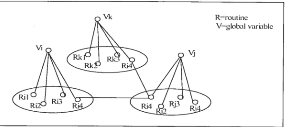
FIGURE2.7: GLoBAL VARIABLE-BASED OB.JECT IDENTIFICATION 35
FIGuRE3.1: MIGRAI ION METIIoI)oLoGv0vERvIEt 39
fIGURE3.2: IDEM. MIGRATION PROCES5MODEL.-REVF:RSE ENGINEERINGPAIU 40
FIGuRE3.3: IDEAL MIGRATION PR0;REsS MODEL—FoRw.Ro EN(;INEERINGP.w 41
FIGURE3.4: PRA(TI(’ALM1GRAi1ON PROfESS Monii 43
FI(;tIE4.1: LEG-wv S\siENI DESIGN&CoNsFRL (IIONAL SntCItIE RE’ovERY 48
FIGuRE1.2: ANALvSIs TERIINoLoGY ILLtSTRATION 50
FIGI RE4.3: RECOvERVArI’ROACIIScIIEM 52
FIGU RE 4.4: V0RKFI.0W 0F DYN.IIC-ANAL\zER 55
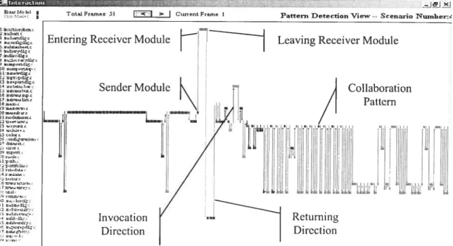
FIGL Ri4.5: F00II’RINF (I) NI) PAIIERN DE[E(IION(II) IEWSFROM D\NIIC—ANkI\’zER 57
FIGURE4.6: C0N5rRtCIIO\ SrktcIt Ri ‘IEW 0FSVs’[FI Et NCIIONALIfl 58
FIGURE4.7: C0L0R REPRESENIAIION SCIIEsIE 0F WEIGH1 VARIANCE GR\I)IENI 59
FI;tRE4.8: Sysrii ft’NcrIoNALFC\ SCENuuo REC0IU)ER 60
FIGLRE4.9: COLL\BORArIOx-INvE5TIGAIOR: A REVERSE ENGINEERING TO0I, FOR CoLLAnoIAnoN
PATTERN AND ROUE REc:ovER AND ANALYSIS 61
FIGURE4.1 0: COllABORATION PAITERN RECOvERY AND VIsUALIZATION 63
FIGuRE4.11: CON(EPI UAL ROUE PAIRS 63
FIt;URE4.12: PARTIAL SYsTENI CoNsFIUCTIONAI, STRuCTURE VISUALIzACION 65
FIGURE4.13: VISUAIIZATION&DYNAMIC ANALYSIS 0F SYSTENI FLXCTIONALITY 67
FIGuRE4.14: [IIERARCHICAL SYSTENI FUNCI IONAI, ABSTRACTIONViEt 68
FIGURE4.15: Sot;RcECoDE HIERCHICL ABSTRACTION Viiw 69
FIGURE4.16: M0nLLf INTERACTION ViEt 70
FIGuRE4.17: MODU LE CONTRIBUTION CONIPARIS0N ViEw 70
Fici Ri4.18: MODuLEPARTICIPATION VIEw 77
FIGuRE4.19: VARIABLE, ROUTINE AND MACRO REFERENcE GRPH w SOURCE-NAVICAroR 72
FIGURE4.20: SOuRCE CODE MoDULE DEPENDENCY ANALYsIS 74
xi
FIGURE4.22: THE DECOMI’OSITION 0F“SGA-C”LEGACY Svs’rENl.78
FIGuRE5.1: OBJEcT-ORIENTED RE-ARCHI fECTURING $0
FIGuRE5.2: RuLE-BASED CLASS REC0VERY PRocEss $1
FIGURE5.3: CONVERTING tJDTINTO A CANDIDATE CLA55 83
FIGuRE5.4: DERIVING COMPOSITION RELU IONSHIP $4
FIGt;RE5.5: ATTACII ROUTINES INTO CANDIDATE CLASS 8V PARAwTER DATA TYPE $5
FIGURE5.6: ATTACH RotIINES INTO CANDIDATE Ciss BY RETURN VALUE DAT. TYPE $5
FIGURE5.7: ASSIGX ROUTINE TOCiss VHtRotT INE’S P..RkIErERSHAVE NIORE tHAXONt
IJDTAS DATA TYPES 86
FIGuRE5.8: CONVERTING GLOBAL VARIABLE INFO CANDIDATE CLASS $7
FIGURE5.9: DERIVING CLASS INHERITAN(E FRONI OI1Y0NAL VARIABLES IN UDT $8
FIGuRE5.10: PROCEDIJRAL CODE 0F C0LItCrloNs INC 91
FIGURE5.11: GENETIC ALGORIFIINI GENERIC PATTERN 94
FIGtRf:5.12: THE INITIAL Port LATION 97
FIGURF:5.13: AIGOIUTHNI 0FOBC(ORDER—BASED CLLSFERI\G) 100
FIGURE5.14: ALGORnHM 0FC—COI(CONfEPTU AI. CLUSFERINGFt)ROBJE(T IDENIIFICAFION)....101
FIGuRE5.15: CONCEPTUAI. CI.tsFEIUNG REstITs IN DIFFF:RENT PRESEN1ArIoN ORDYRING 102
FIGURE5.16: SANIPLE 0F DYNAMIC ENFITY INTERACTION DIAGRANI 103
FIGURE6.1: INCRENIENIAI.MIGRATION f/IODtI 107
FIGURE6.2: INCRENIEN[ALMIGRATION IIItSIRATION 10$
fIGtRE6.3: MENIBER Et M lION DLH’.I [ION 111
FIGtRE6.4: Ftzzy SYNTHESIS 0F MIGRATION PIU0IUT\ 11V Two CIuTERI 112
FIGURE6.5: BRIDGE CODE CON5rRtCII0N t 11HJNI 115
FIGtRE6.6: JAvA CODE (MICRATÈD PARC) CALLS LEG..CY ROUTINES 115
FIGURE6.7: LEGAcY ROtrINE CALLS JAvA CODE 116
FIGURE7.1: StPPOWIING CLASSICAL PROJECT SCIIEDtLING TECHNIQUES IN C4RIBO(/ 119
FIGURE7.2: CLASSICAL TASK DEI’ENDENCv DIAGRANI 120
Fl(;IRE7.3: PLANNING NOTATION IN C4RFflO(1 121
FIGURE7.4: CRIBO1 ENH.ANCED SYNCHRONIZATION NoI.TIoN IN PRO.JE(r PI\N1N(; 123
FIGURE7.5: PROJECTPLANNINGIN GAR,Bo,: 124
FICU:RE7.6: CARIBOt: COLLABoRTIoN TASK PR0GRES5 MODEI 127
FIGtJRE7.7: CALCULAHON0F PROGRE5S INDEX 128
FIGuRE7.8: COLLABORATIoN NETwORK 129
FIGuRE7.9: COLLABORATIVE SOFTwARE DEVELOPMENT CONIMtJNICA1ION MODEI 132
FIGuRE7.10: CARIBOu PERSONNEL MATCHING MODEL: QUESTIONTRANSACTIONPROCESS 133
xii
FIGURE8.1: ArroIATIc C0LUAB0RxrI0N PA1FERN REc0VERY. (THE NIMBER INDICATES FRAME
ID) 142
FIGLJRE8.2: DETECTEDCOLUABORATION PATTERN 143
FIGURE8.3. MoDULE C0NCEPTUAL ROUE REcoERv 143
FIGURE8.4: ANALYZINGTWOMODULES WITHIN A COLLABORATION: TRANsArnON (LEFT) AND
TRAN5ARR.n’ (RIGHT) 145
FIGURE8.5: SUMMARY 0F EVALuATION RE5LLIs 147
FIGuRE8.6: OB,JECT MODEU ELICITATI0N 148
FIGuRE8.7: OBJECr M0DEUING 0F “GALons 151
xiii
List of Tables
TABLE2.1: HIEItARCHICAL SIMILARITY CLFISTERING ALCORITH 31
TABLE4.1: DvNAIICTRACINC DATA FORMAI 49
TABLE4.2: MUs CONSTRLCi’IO’,: DEaniposmoN ALcolul HM 76
TABLE5.1:ALL VR-RELX[10NS, AND ONE 0F RR-RELATIONS IN COLLECTIONS 91
TABLE5.2: DvNAIIC OBIErU IDENTIFICATIoN ALC0IUFHM 103
TABLE7.1:SENIANTICS 0F THE MODELING ELENIEN1’s 121
TAIlLE7.2:STATIC ATTRIBLTES 125
TABLE7.3:DYNAMIC ATTRIBUTES 125
TABLE7.4:PROCREss METIZICS DEFINIFION 127
TABLE8.1:SoIRCE C0DF: CHAIACTERI5TIC5 OFTHE ExAIINED SvsrEIs 137
TABLE8.2:EXPERINIENI TOOLS 138
TABLE8.3: LjsI 0F PAn ERNS 142
TABLE8.4: DEC0NIP0SInoN 0F “Exp1vr” LEUAv SvsFENI 145
xiv
List of Abbreviations
00: Object Oriented
UML: Unified Modeling Language
LOC: Lines of Code
AST: Abstract Syntax Tree
Cf G: Contro] Flow Graph
Cf G: Context f ntïty Graph
CORBA: Common Object Requesi Broker Architecture
OAP: Simple Object Access Protocol
MU: Migration Unit
WfNIS: Workllow Management Svstem
UDT: User Defined Data Type
SCC: Strongly Connected Components
DA: Directed Acyclic Graph
GA: Genetic algorithms
GOAL: Genetic-based Obj ect identification Algorithm
C-COI: Concepttial Clustering for Object Identification
OBC: Order-Based Clusterïng
JNI: Java Native Interface
API: Application Programming Interface
CPM: Critic Path Method
PERT: The Program Evaluatïon and Review Technique
YAWL: Yet Another Workflow Language
Chapter I. Introduction
1.1
Motivation
During the Iast three decades, a considerable amount of software was developed using procedural languages. For example, only the systems written in Cobol have been estimated to account for more than 100 billion LOC {CoyOO]. Legacy software inay be defined inforrnally as an old software system that we do flot know much about its design, but that is stili performing a useful job. In many cases, it is critical to the operation of its owner [Ben95]. Although the terrn “legacy” implies sornething that is preciotis and
inherited, in the dornain of software engineering, this word nearly represents decision uncertainty: discard this old but mission critical software system or continue to evolve it with high maintenance cost. Nevertheless. ignoring the prevalence oflegacy applications is ditticuit. and it is oftcn net possible te replace or modifv them easitv [LucQ7].
During the past decade, object—orientcd technology (or simplitied as objcct technology)
bas achieved great success in software system development. Object-orientcd paradigm
supports many modem programming methodologies, such as information hiding, inheritance, polymorphism, dynarnic binding, etc. Object technology facilitates the design and understanding of a system with abstraction. It provides various desirabf e features that greatly benefit to the practice of software deveÏopment and maintenance. As
a resuit, software systems implemented in 00 languages are in general more reusable and
more maintainable. On the other hand, nowadays, rnany vital legacy software systems that wre developed before the appearance of object technology are chronicalïy facing the difficuit question of maintenance. Most of these systems are more than a decade old on average, designed only with the consideration of hardware limitations, and are
continuously modified to meet the evolutionary needs. Such legacy systems present a high level of entropy: the source code bas become ill-stmctured, poorly self-documented, and weakly modeled. In addition, the documentation may present an inaccurate picture of what bas been actually implemented [Ric97]. As a resuit, the high level of entropy cornbined with imprecise documentation about the design and architecture make their maintenance more difficuit, time consuming, and costly. On the other hand, these systems have important economical values. A large arnount of domain business knowledge has already been coded in legacy software. For the strategic assets they have preserved, it’s impractical to discard them. Meanwhile, sirnply redesigning and redeveloping them by using modem technology is exposed to tremendous cost and risk. To preserve the high economic value of those legacy systems and rneamvhile make them benefit from the advantages ofobject technology, migrating legacy systems towards object technology bas been advocated as one of the best practices [MelOO]. This strategy focuses on leveraging existing legacy software assets while minimizing the risks involved in re-implementing large-scale mission-critical legacy applications [Uma97].
7.2
Problem Statement
In 1995, Bennett defined “legacy systems” as “large software systems that we don’t know how to cope with but that are vital to our organization.” [Ben95]. The Free On-Line Dictionary 0f Computing (FOLDOC) defines as, “A computer system or application program which continues to be used because of the prohibitive cost of replacing or redesigning it and despite its poor competitiveness and compatibitity with modem equivalents. The implication is that the system is large, monolithic and difficult to modify and evolve.” {HowO2]. Sommerville defines it as “Older software systems that remain vital to an organization” [SomOO]. After many years of maintenance, the quality of operation and maintainability has deteriorated drarnatically due to many reasons, such as lack of up-to-date documentation, Iost of key personnel, shift of technology of inter operating peripheral systems, etc. Moreover, legacy systems usuatty consist of millions of unes of code, and a significant amount of business logic. Therefore, they represent an
important investrnent for their owners [Gam95]. From these, it’s flot difficuit to find the characteristics of tegacy systems:
• Old, using technologies that are flOW obsolete;
• Stili perforrn crucial work foi- the organizations, and they represent a significant investment oftheir owners;
• Generally large, lacking of accurate documentations; • Difficuit to understand, hence hard to maintain.
1.2.1 Software Evolution
lnforrnally, software evolution refers to ail those improvement activities that take place after a software product bas been delivered to the customer. A formai definition used by the Research lnstitute in Software Evolution at the University of Durham is: “The set of
activities. both technical and manageriai, that ensures that software continues to meet organizational and business objectives in a cost effective way”. According to Bennett et
al., evolution is a particular phase in the maintenance process, imrnediateiy after initiai delivery, but before servicing phase out and close down [BenOO]. n reaiity, a software system wiii undergo maintenance throughout its life-cycie, such as correcting faults, improving performance, adapting to new environment, or adding new functionalities [Chi9O]. Based on the empiricai experiments on 0S360 using a sequence of releases, Lehman firstly defined the iaws of software evolution [Leh85]. His software evolution laws state that:
Law 1: “Software which is used in real-world environrnents must change or become
less and less useful in that environment.”
Law 2: “As an evolving program changes, its structure becomes more complex, unless active efforts are made to avoid this phenomenon.”
From these, we can see that software evolution is a continuous progress of software fixing, adaptation, and enhancement.
1.2.2 Legacy Dilemma
Although legacy systems were implemented with old technology, they stili provide important value by performing crucial work for their organizations, and usually they represent a significant investment and years of accumulated experience and knowledge [Bat98J. By applying stnictured programming technology, legacy systems soon rneet the problem of continue evolution: structured programming is flot designed to map onto entities in the real world. This makes it very hard to understand the original design when maintenance work is inevitable. The owner will eventually face what is caÏled the legacy dilemma [YanO3]{Rarn99]:
• It is expensive and risky to replace the legacy system;
• It is even more expensive to maintain the legacy system.
Consequently, there is an urgent need to find ways to make legacy systems more maintainable without disrupting the operation oftheir owners.
1.2.3 Direction
In addition to improving legacy system quality, the reengineering process should also adopt new technologies to rnodemize/revive the target system, and ensure the efficient preservation of dornain knowledge that has already been embedded in the legacy system. On the other hand, since most business activities typically involve multiple applications, this requires the integration of heterogeneous systems. To maximize the operational efficiency and leverage the value of existing systems, a suitable way to solve the legacy problem is to migrate into new open platforms. Moreover, sticking on aging or obsolete technology may cause maintainers eventually lose their enthusiasm [Tan98], Most software engineers would rather work on new deveÏopment projects which apply state-of the-art technologies than maintain old applications that rely on obsolescent technologies — although this type of task also represents a different kind of challenge. As the research work of Tan and Gable [Tan98] illustrates that, compared with developers, there’s a great tendency that maintainers will more easily depart their appropriate attitudes towards
maintaining legacy software which is based on aged technology. According to the legacy dilemma, neither replacing nor continuous maintaining legacy systems is acceptable. Iherefore, migration toward new emerging technology is an appropriate direction.
Object-oriented systems can be designed and implemented in tenns of artifacts that closely follow real world entities [Garn95]. It is advocated as a way to enhance software systern’s understandability, correctness. robustness, extendibility, and reusability, the key factors affecting software quality [PreOl]. Therefore, object technology makes it more natural for programmers to design and construct software models based on real world concepts. Additionally, the use of abstraction, encapsulation, inheritance, and other object-orientation techniques make object-oriented systems easier to understand and to maintain. Consequently, migrating an existing legacy procedural software into object oriented paradigrn is an appropriate approach to increase its understandability and maintainability [Jes99b]. Nevertheless, the migration itselfis not an easy task. Extensive
research lias already been engaged in this field since the emergence ofobject technology [Jes99a]. With the steacly progress of IT industry, the quick expansion of object technology in the software engineering dornain bas made it urgent to solve the “legacy dilemma”.
1.3
Thesis Objectives
In this thesis, we propose a rnethodology and a set of techniques to assist software engineers migrating legacy systems towards object-oriented technology. We aim to improve the maintainability and reusability of target systems and facilitate the further evolution towards object technology. In particular, the objectives of our research can be summarized in the following points:
• Reveal the pertinent issues conceming legacy system evolution and reengineering. • Provide a comprehensive methodology framework to migrate legacy system towards
• Develop tools and techniques to reduce the complexity and ensure the quality of the migration process. These include the development of legacy software decomposition, legacy design recovery, re-architecture, and techniques of identifying object models. • Propose an incremental migration process model. The migration process thereby
consists of a sequence of migration routes that progressively change the state of the system. The initial status corresponds to the original system and the final state corresponds to the target modernized system. The proposed re-engineering process aims at providing a comprehensive control mechanisrn by which optimized migration routes can be deterrnined.
• Develop a migration supporting system. A coltaborative migration project involves rnany people working together without the harrier of time and space differences. However, the large scale of collaboration in a typical migration project Iacks of sufficient supporting techniques to faci I itate proj ect plann iiig, monitoring distributive collaboration tasks, anci communication. Our prototype of migration supporting system is designed to tackie these three important issues.
7,4 Thesis Overview
The rernaining ofthis thesis is organized as follows:
Chapter 2: State of the Art: Literature Review
in this chapter, we will discuss the related research fields of our study topic in the Software Engineering domain. We will have a short literature review of the of related research.
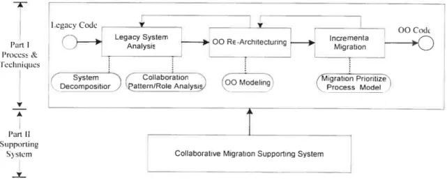
Chapter 3: Migration Methodology Framework
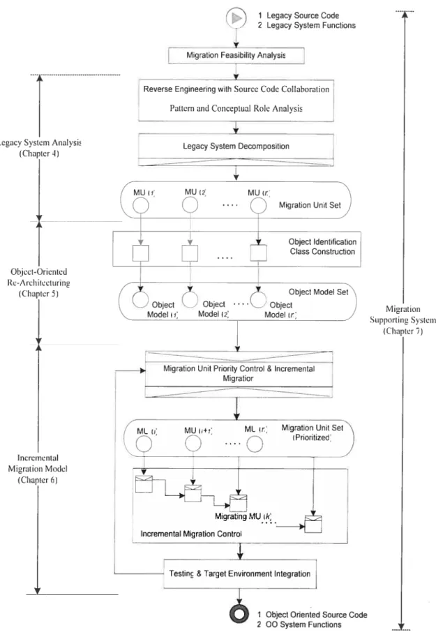
In this chapter, we will present the blueprint of our migration methodology framework. It is constituted of four major components, namely legacy system analysis, Object-Oriented re-architecturing, incremental migration model, and
migration supporting system. The details for these fotir components wilÏ be presented in each ofthe following four chapters.
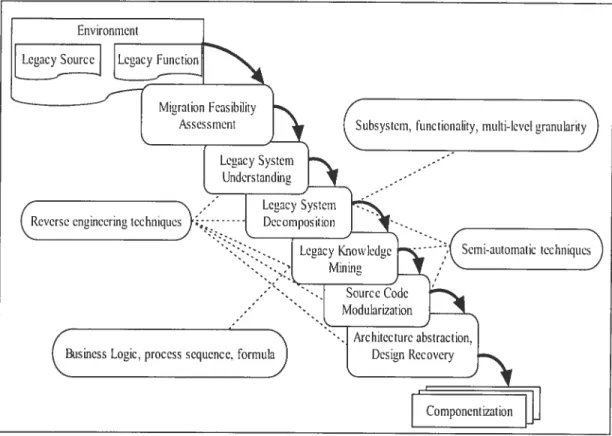
Chapter 4: Legacy System Analysis
In this chapter, we wilÏ present our legacy system analysis techniques. We focus on two directions, one is the lcgacy system decomposition, and the other one is the code collaboration patternlrole recovery and analysis.
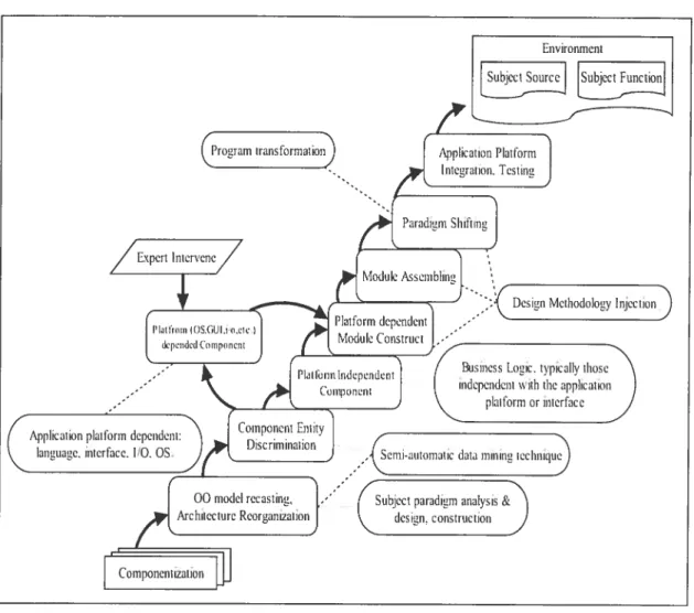
Chapter 5: Object-Oriented Re-architecturing
In this chapter, we will discuss three majortechniques that we have deveÏoped to
conduct object modeling of legacy systems.
Chapter 6: Progressive Migration
In this chapter, we wilI present our progressive migration approach. The incremental migration process is designed to contain multiple iterations, each of which wiIl only focus on migrating a certain part of the target system, leading to an increase in the portion ofthe renovated code and to a respective decrease ofthe legacy code. A fuzzy expert system is applied to prioritize the migration sequence.
Chapter 7: Migration Project Supportïng System
Ihe large scale of collaboration in a typical migration project lacks of sufficient support techniques to facilitate project planning, monitoring distributive collaboration tasks, and communication. In this chapter, we will present our approach and the prototype of Caribou: a supporting environment for migration project, to tackle these important issues.
Chapter 8: Experiment and Evaluation
In this chapter. we will discuss the experiments that we’ve conducted to migrate Iegacy systems into an object-oriented paradigrn. We apply our migration approach and techniques to conduct these experiments. The resuits in turn validate our approach and also indicate potential improvement ofour techniques.
Chapter 9: Conclusion
In this chapter, we wilI discuss our contributions and the directions of our future work.
Chapter II. State of the Art: Literature
Review
In this chapter, we xviii discuss the reiated research fields of our study topic in the Software Engineering dornain. Legacy migration is a research branch within tegacy system maintenance and evolution. The driving force is the desired features provided by new technology and the inherent limitation of legacy systems. Reverse engineering and re-engineering are the major two fields that address different aspects ofthe iegacy system migration problem. In this chapter, we wiil present a literature review of the recent advancements in these fieÏds.
2.7
Reverse Engineering
Software reverse engineering is related to program property recovery as well as re
manipulation of system views. Chikofsky and Cross Nrstly intwdticed the taXonomy k)r
reverse engineering and design recovery. They defineci reverse engineering as “the
process of analyzing a subject system to identify the systems components and their inter
relationships, and to create representations of the system in another form at higher levets
of abstraction.” [Chi9O]. We should note that reverse engineering itself does flot change the subject system or create a new system. It is a process ofexarnination, not a process of alternation. Reverse engineering inciudes the following research areas [Chi9O]:
Inventory/Analysis: applies source code analysis techniques and abstraction models to evaiuate the technical, functionai, and architectural aspects ofthe target system.
Positioning: focuses on restructuring the system to enhance its quality, or to improve source code understandability without changing the system external behavior.
Re-documentation: represents the system with a sernantically-equivalent depiction in order to assist comprehension.
Design Recovery: aims at extracting rneaningful bigher-Ievel abstractions ofa system. Many reverse engineering tools focus on extracting the structure of a legacy system with the goal of transferring this information in order to reengineer or reuse it [MulOO]. Over the past ten years, reverse engineering research bas explored a wide range of fields in this domain, i ncl uding subsystem decomposition [Bro95] Urna97], concept synthesis [Big94], program design pattem matching [Gam95][Ste98], pmgram siicing [Tip95][TakOl][RusO2], analysis of static and dynamic dependencies [Sys99], object oriented rnetrics [Chi94][BeyOl], and software exploration and visualization [Pri93][LudO2]. In general, these kinds of analyses aim at addressing specific interests of program properties.
Reverse engineering research work generalÏy follow a three step approach: 1) Facts extraction 2) Abstraction, and 3) Presentation. Tilley et al. are among the flrst researchers to proposed the general frarnework of reverse engineering with the purpose of program understanding. They surnrnarized these activities as “Data Gathering, KnowÏedge Organization and Information Exploration.” [Ti196]
2.1.1 Program Analysis
]ackson et al. defined program analysis as “The extraction of behavioral infoniiation from the software, represented as an abstract model or code” [JacOO]. It is the (automated) inspection of a program to infer its properties. In the past decade, various kinds of analysis techniques have been developed: static and dynamic, sound and unsound, operational and declarative [JacOO]. Extracting design moUds is the pivot for exploiting code analyses. Harandi and Ning flrstly discussed the four levels of abstraction
for program analysis: implementation, structural, functional, and domain [Har9O]. The implernentation-level view examines individual programming constnicts; the program is typically represented as an abstract syntax tree (AST), symbol table, or plain source text. The structural-level view examines the structural relationships among the program constructs; dependencies arnong program components are explicitly represented. The functional-level view examines the relationsbips between program structures and their behavior (function). The domain-level view examines concepts specific to the application dornain. Program-analysis techniques may also consider source code in increasingly abstract forms [NotO2][Nie99], including raw text, preprocessed text, lexical tokens, syntax trees, annotated abstract syntax trees with symbol tables, control/data flow graphs, program plans, and conceptual models.
Reasoning about code is another core activity of program analysis. Zefler concludes four well-known software analysis reasoning techniques [ZelO3]: 1) Deductive program analysis: from an abstraction into the concrete—for instance, analyzing program code to deduce what can or cannot happen in concrete runs, such as static analysis generates findings without executing the program. 2) Observational program analysis: generates findings from a single execution of the program, 3) Inductive program analysis: summarizing multiple observations into an abstraction. It generates findings from multiple executions of the program. 4) Experimental program analysis: for isolating causes of given effects, e.g. narrowing down failure inducing circumstances by systernatic tests.
2.1.2 Software Comprehension
The goal of software comprehension is to acquire sufficient knowledge about a software system so that it can evolve in a disciplined manner [Sco98]. During the process of software evolution, legacy systems have gone through years of maintenance. Changes have inevitably been applied to the source code, such as adding functions, fixing bugs, adapting with new environment, etc. [Chi9O]. Meanwhile, many have failed to take a practical concem of keeping the documentation up-to-date [Ric97]. As the software
systrne ages, the task of maintaining becomes more complex and more expensive. Poor design, unstmctured programming methods, and crisis-driven maintenance can contribute
to poor code quality, which in tum affects understanding. In many cases, the code is the
only reliable source of information about the system [BiaOO]. As a resuit, the process of reverse engineering has focused on understanding and analyzing the code.
Storey et al. defined program comprehension as “The task of building mental models of the underlying software at various abstraction levels, ranging from models of the code itself to ones of the underlying application dornain, for software maintenance, software evolution, and reengineering purposes.” [St000]. It is a central activity during software maintenance: Corbi reports that up to 50% of the maintenance effort is spent on trying to
understand code [Cor9O]. According to Rugaber’s general survey on program comprehension, the program understanding covers several important aspects including cognitive processes and automated techniques [Rug95].
The cognitive model of program comprehension models the mental processes involved
in program understanding. In most cognitive models, hypothese are key drivers of the
comprehension process. The moUds describe how programmers generate and verify such hypotheses [May95].
The other aspect of program comprehension focuses on deriving documentation from source code. The purpose is to re-generate the representation of a software system that allows programmers to gain a better understanding. This type of program analysis is caÏied documentation generation. Deursen et al. listed four criteria for re-documentation [Deu99]: 1) Documentation should be available on different levels of abstraction; 2) Users must be able to move smoothly from one level of abstraction to another, without loosing their position in the documentation (zooming in or zooming out); 3) The different levels of abstraction must be meaningfiul for the intended documentation users; 4) The documentation needs to be consistent with the source code at ail times. Here we list several representatives of systems re-docurnentation. DocGen is a documentation generation tool aimed at re-documenting legacy systems written in languages such as COBOL, DB2, JCL, and proprietary languages [Deu99]. The Rigi system can extract, navigate, analyze, and document the static structure of large software systems [KieO2]. NDoc is a source code documentation tool for the C# .net language [NesO2J, and
JavadoclM is a tool for generating API documentation in HTML format from doc comments in Java source code.
Most of the rernaining aspects focus on techniques that help software engineers to understand target systems [BalO 1]. Tilley surnrnarized program understanding techniques into three categories [Ti198]: 1) Behavioral approach, which emphasizes how the system works. It is top down and inductive, using a goal-driven method of hypothesis postulation and refinernent based on expected artifacts derived from the knowÏedge of application dornain. This approach begins with a pre-existing notion of the functionality of the system and proceeds to earrnark individual components of the system responsible for specific tasks. 2) Functional approach. which relies more on the knowledge of the imptementation domain to create abstract concepts that may map to the application domain and to the system’s functional requirernents. it is bottom up and deductive. This approach reconstructs the high-level design of a system, starting with source code, through a series of concept recovery steps. 3) Opportunistic, which combines top-down and bottom-up comprehension models to define how a software engineer understands a program. This opportunistic approach involves creating, verifying, and modifying hypotheses until the entire system can be explained using a consistent set ofhypotheses.
2.1.3 Software Visua]ization
Reverse engineers also apply other means to facilitate the software understanding process. Software visualization is one of the most promising techniques. Charters et al define software visualization as “a discipline that makes use of various forrns of imagery to provide insight, understanding and to reduce complexity of the existing system under consideration.” [ChaO2]. They emphasize that visualization provides a view of quick program comprehension that etiminates the overwhelming complexity of software systems. Stasko et al. describe software visualization as “the use of computer graphics and animation to help illustrate and present computer programs, processes, and algorithms.” [Sta98]. Many visualization systems have been developed to assist program understanding. Here we list two of those most representative works. The SHriMP
visualization tools -- Simple Hierarchical Multi-Perspective views, use a nested-graph
fomialisrn and a fisheye-view to manipulate large graphs while providing context and preserving constraints such as orthogonality and proxirnity. SHriMP has been incorporated in the RigiSystem [KieO2]. CodeCrawier is a language-independent reverse engineering visualization tool for systems written in object oriented programming languages [LanO3]. It combines metrics and visualization to provide deep inspections of target system.
2.1.4 Architecture Recovery
Software architecture consists of the computational components, their interactions (connectors), and the constraints on them. Bass et al. define software architecture as “The structure of the computing system, which comprises software elernents, the externally visible properties of those elernents, and the relationships among them” [BasO3]. ANSI/IEEE Standard describes architecture as “Ernbodied in its components, their relationships to each other and the environment, and the principles goveming its design and evolution” [StaOO]. The latter definition is intended to encornpass a variety of uses of the term by recognizing their underlying common elements. The key point among these definitions is the need to understand and control those constnictional elements in order to
capture the system’s utility.
Architecture recovery, also known as reconstruction [StoO3], is the atternpt to extract software architecture from the source of the target system {Kaz99]. It is aimed at supporting the process of program understanding and reengineering for the purpose of software maintenance and evolution [BriO2]. It provides engineers with a global view of the system. This overview indicates the main components of the system, how they are
related, and the constraints among them [EdeO3]. During the past decade, many automatic techniques for architecture component recovery have been developed. Koschke proposed a frarnework to cÏassify them based on a comparison of 23 techniques. He
introduced the categorization of connection, metric, graph and concept based extraction approaches, and anaÏyzed the commonatities and variability ofthese techniques [KosO2],
His research work shows that none of those autornatic architecture component recovery techniques bas the satisfactory precision. He further pointed out that serni-autornatic techniques should be more suitable for the recovery work.
Architecture recovery primarily comprises two parts. One is the discovery of components (the computational portion); the other one is the detection of connectors (the interactions and communications arnong components). One major research topic in the first part is the detection ofsubsystems [Lak97], and the recovery ofobjects and abstract data types [KuiOO]. Connector recovery is especially important for concurrent and distributed systems [Fiu96]. However, for most Iegacy systems, they are sequential and monolithic. Function eau is the rnost primitive and dominating type of connector of such systems [KosO2].
Riva et al. developed an architecture extraction process and the environment supporting it [RivOO]. The process consists of four parts, which are appïied iterativeïy in order to extract an increasingly reflned view of a systern’s architecture. The four parts are: 1) Definition of architecturally significant concepts. 2) Data gathering, in which a model of a system is built in terms of the concepts defined in the first step. 3)
Abstraction, in which the model is enriched with domain specific abstractions that lead to a higher view of the system. 4) Presentation of the rebuilt architecture in a series of formats, such as graphs, hyperlinks, and UML diagrams, representing the required architectural view-Iogical, process, physical and developrnent.
Another interesting direction in this field is the detection of the architecture rationale, Deursen proposed a frarnework to recover the architecture rationale of architectural decisions [DeuOl]. It includes three parts: 1) Use existing documentation, comments, and tog messages as rationale pointers: System browsers aiming at architecture presentation can integrate these with other views. 2) Recognize design pattems, which aims at capturing specific rationale knowledge of recurring solutions. For procedural systems, design pattem recovery is complicated by the lack of an explicit pattem catalog. 3) Record rationale by combining architecture browsers with either simple annotation mechanisms or more involved rationale capturing tools. The recovery of architecture rationale can significantly support the understanding process.
2.2
Re-engineering
Also known as renovation and reclarnation, the “Reverse and Reengineering Taxonomy” defines re-engineering as “The examination and alteration of a subject system to reconstitute it in a new fonii and the subsequent implernentation of the new forrn”, whilst forward engineering is defined as “The process of moving from high level abstractions and logical, implementation-independent designs to the physical implernentation of a system.” [Chi9O]. Koschke provides a visual representation of the relations arnong those terrns as illustrated in Figure 2.1.
2.2.1
Restructuring
Software restructuring is the transfonnation from one software representation forrn to another at the same relative abstraction level, while preserving the subject system’s external behavior (fttnctionality and semantics) [Chi9O]. It is aimed at improving program’s quality while avoiding the modification of system functionality. Restructuring is often used as a form of preventive and perfective maintenance to improve the physical state of the subject system with respect to some preferred standard [E1002]. A related term is refactoring, which is also a behavior preserving program renovation. However, il is a special case of restructuring, in the sense that it is always used in the context of
Rq
tiîi’iiiiI)
esj
n
IL•fl’::IIF._Li fi
I..•I[1I’.I III I
ii
t:otI(’
object-oriented programming, and typically at the level of programs (i.e., source code) [Fow99]. Restmcturing can be more general, it can be applied to any kind of software artifact, in any language, at any level of abstraction [MenO4]. Using Bowdidge’s classification, software restnicturing can be divided into four categories [Bow9$]:
i. Scoping restructuring: alter the location where entities within a program are
declared. An example could be moving a variable declaration out of a procedure, making it visible to other procedures in the system.
ii. Syntactic restructuring: alter specific characteristics of entities, such as converting compound staternent structures into other, equivalent structures.
iii. Control restructuring: allow one to re—order the control structure witbin a
program. This class of transformations not only requires control analysis, but also demands extensive data analysis.
iv. Abstraction restructuring: alter the data or code abstractions. It is often applied to
restructure object-oriented systems. For example, it may be desirable to move a member from a chilci into its parent object to refine the inheritance relationship between objects. Code abstraction allows one to replace a staternent, or sequence ofstaternents with a procedure call.
A number of techniques have been proposed to implement restructuring. The main idea
is to manipulate abstract program representations. Term rewriting, a technique used to
specify a software system as a set of recursive equations, has been applied in the restructuring tools for COBOL systems [Bra9$]. Griswold’s tool for Scheme combines the abstract syntax tree (AST), control flow graph (CFG), and program dependence graph (PDG) [Gri9l]. C_Structure is based on the AST and virtual control analysis [Mor98], and context entity graph (CEG) were developed to support specific language characteristics [E1o02].
2.2.2 Software Re-engineering
Reengineering is the analysis of existing software systems and modifying them to constitute in a new form. It seeks to clarify the understanding of software, alter the
characteristics of code, and improve the functionality/performance ofthe system. It is one of the research areas that aim at mastering software evolution. Actually, many factors such as business requirement changes, technological infrastructure shift etc. may ail contribute to the constant dernand for radical software change. Since the cost of system replacement is high, reengineering is hence often a better choice [Aeb97]. Software reengineering generally bas three goals: 1) Enhancing system functionality; 2) Improving rnaintainability and reliability; 3) Migrating towards more advanced technology platforms. Since maintenance and change introduce new errors, the systern’s quality gradually deteriorates. Meanwhile, as systems grow, maintenance cost also increases. Therefore, one major objective of software reengineering is to re-design the system to improve system functionatity and maintainability.
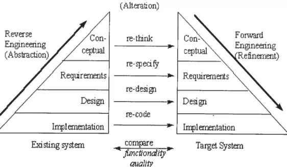
The reengineering process includes studying the system, making a specification at a higher abstraction level, adding a new functionality to this specification. and developing a completely new system based on the original one by using fonvard engineering techniques. Byrne bas proposed a process mode! for reengineering with three parts: Reverse engineering, Alteration, Forward engineering, which lie visualized as illustrated
in Figure 2.2. (Mterati on) re-t1nk re-spedfy re- ciesi gn re-code cornpre c’oahty
Figure 2.2: Re-engineering Model [Byr921.
F owar’i Engineering C c’n. cep tuai Requirements Design Existing systern I;yj1erntation TargetSystern
The SEl Horse-shoe Mode! (sec Figure 2.3) is simi!ar to Byrnes mode!, but it takes a software architecture perspective on reengineering. Horse-shoe mode! aims to integrate the code-!evel and the architectural-!evel reengineering views. In its most fundamenta! form, there are also three basic reengineering processes [Car99]: i) Architecture recovery: the ana!ysis of existing systems and the extraction of high-leve! abstraction artifacts from source code. This recovered architecture is analyzed to va!idate the conformance with the as-designed” architecture. The discovered architecture is a!so evaluated with respect to a number of qua!ity attributes such as performance, modifiability, security, and reliabi!ity. ii) Architecture transformation: the logica! transformation of the high level abstractions. The ‘as-built’ architecture is recovered and then reengineered to a desirable new architecture. it is re-evaluated against the systems qua!ity goals and subject to other organizational and economic constraints. iii) Architecture-based development: the implementation of the desired architecture. Code-level artifacts from the legacy system are often wrapped or rewritten in order to fit into this new architecture.
icchfte cture Tra risî’:’rrnat o ri
.4chftecture .?ir:hftecture
/
Fp’ri Rep n.zçi:hfte cture .#i:iiftei::ture
Pco’xery/ hased
D:’n trns nce . De’.’eloprnent
Fur ctiori-le tel Furiotion-level
r’
‘ri priQde Swjcture’ Code Structure
Rep ri ° Rep’n
1 i I. r
‘
7
Source Te Legacy w Sern
Pp’n Source Source
Figure 2.3: SEl Horse-shoe Reengineering Model [BerOOj.
Base r—___ Desired
.4chftecture I
i_— Zjrj ftecture
prrr Prcgar
Z3
Migration towards Object Technology
With the constant developrnent of object-oriented technology, migrating legacy software systems into object-oriented platforms has gained significant attention over the past few years [LucOO] [ZouOl] {MarO2]. This research aims to increase legacy system’s rnaintainability, reusability, and overail quality by means of reengineering it into an advanced paradigm, narnely object oriented platfonn. By this way, the migrated legacy system may largely benefit from the advantages of object technology.
Legacy system migration encompasses rnany research topics. It addresses issues of reverse engineering, reengineering, obj ect identification, schema rnapping/translation, data transformation, hurnan computer-interaction, testing, migration process control, etc. In the literature, migrating legacy software towards object technology can be further divided into two directions: the migration methodology, and the object identification technique. For the former one, the focus is on developing a general migration solution; the latter one is dedicated to building up a particular technique to conquer the object
modeling issue in the migration process. The majority of the published research is concentrated on the latter direction.
Martin and Muller applied the Ephedra prototype to transforrn C source code into Java programs {MarO2]. Their approach includes three steps: (i) insertion of C function prototypes, (ii) data type and type cast analysis, and (iii) source code transformation. They aim at translating parts of C code into Java platforrn automatically, thus to avoid an
entire redevelopment of business logic that has already been embedded in the existing system. Nevertheless, Ephedra has two major weaknesses in fulfilling its automation goal. One lies in its lack of concrete methodology to identify candidates for classes and their members; the other one lies in that it is hard to apply their method in fully automating the process oftranslating completely different languages. The difficulty exists in the syntax and semantic differences.
Gonzalez et al. proposed another approach to reengineer Iegacy procedural software systems into object-oriented technology [Gon98]. It includes two major processes: translation and transformation. In translation, the source code artifacts written in the original language will be substituted by the target language’s artifacts without significant
modifications to legacy software architecture; transformation is a process that changes the original architecture into a new object-oriented architecture. In this approach, a procedural program is viewed as a poorly designed 00 program with a single large class. The goal is to decentralize this large class into many smaller classes to carry out 00 design. Park et al. ftirther proposed an Object-oriented model Refinement Technique tORT) to btiild a final object model [Par9$]. It first arranges the information acquired from a reverse engineering process into a specification information tree; then it applies a tree-structured data dictionary to compare the entities in the specification information tree with the information from forward engineering, thus to finally produce the refined moUd. However, in this approach, deriving a proper 00 moUd from the output of reverse engineering and forward engineering stiit remains a problem. This is rnainly because the amount of design information, narning conventions, and structures of these two processes may be inconsistent.
2.3.1 Migration Forms
To migrate a legacy system towards object technology, there are several forms suitable for a certain migration project (sec Figure 2.4). We summarize them as following.
The Pure Language leveÏ Transfbrnia tian. A significant effort is put on the issue
of syntax and semantic swaps between different languages [AndOO] [MarO2], especially those having nearly the sanie sernantic base [Fan99J, such as C and C++. The benefit of this kind of research work is to facilitate the automation of the migration process at the pure language conversion level.
Migrating Ïegacv systein towards distributed net-centric 00 computïng
environment. This is to migrate standalone legacy systems into a distributed
object computing moUd to fit with the net-centric (such as internet) environment [LiOOJ [LucOO]. Another direction is towards web computing platform. With the rapid growth of e-commerce, there’s a large demand of migrating Legacy information systems into web platforms. One approach is migrating the computation model from standalone computing moUd into weh-hased 00
computing mode! [Pat99] [ZouOl]. By providing a framework [ZouOl], this approach aÏlows the identification ofreusable business logics from legacy system in the fonn of legacy components, wrapping them into CORBA components to enable remote access, and finally transiating into SOAP (simple object access protocol) to enable the internet application. The other direction is migrating the interface of legacy systems into web-based user interfaces {MelOO].
u A4igrating Ïegctcv in/àrmation svstem (Dcttabase centric) towards modem object
orientecÏ database ptatJàmm. A large portion of legacy systems are data centric
applications which rnainly depend on the database management system. To modemize this type of legacy systems, the migration of data and host DBMS into an object-oriented database is the key issue {]es99b] [BiaOO]. They use a data centric approacli to migrate the data table from a legacy database system into an Object-Oriented database system. They use the new database system to construct the 00 application.
Figure 2.4: The Forms of Legacy System 00 Migration
2.3.2
COREM Approach
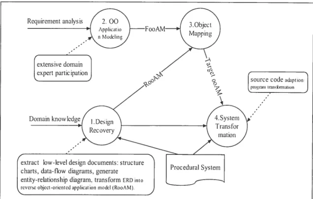
COREM: Gaïl et al. proposed an expertise centered total migration framework [Gal95]. This approach aims at providing a sequential re-engineering model. The
migration process is well defined as a sequence of a bunch of activities together with their sub-objectives (see figure 2.5). Activities are perforrned separateÏy; each will deal with a particular issue of legacy migration. No partial object-oriented resuit is available until ail the activities are finished. It’s a natural method since most reengineering activities eau be mode(ed in a sequential way, thus facilitating the organization of a linear migration process.
The migration process is divided into several major parts, domain human experts are extensively used to help the understanding of iegacy architecture and the elicitation of object-oriented models. The legacy system migration process consists of four main steps:
j. Design Recoveiy, in this step different Ïow-level design documents (i.e., structure charts, dataflow diagrams), an entity-relationship diagram, and an object-oriented
application models (calied reversely generated object-oriented application model,
RooAM) are generated from the source code ofthe procedural program.
Requirement analysis
socirce code aptioi
tIU,%k)IflIt Ion
J
ii. Application Modeling, based on the requirernents analysis of the procedural input
program, an object-oriented application model (calledjbrward generated object oriented application inodeÏ, FooAM) is generated, working as input for the following object-mapping process.
iii. Ob/ect Mapping, in this step the elernents of the RooAM are rnapped to the
elements of the FooAM resulting in a target application model (target ooAM). The target ooAM represents the desired object-oriented architecture and is used for perfomiing the needed source-code adaptations.
iv. Source-Code Adaptation, the source code adaptation step completes the program
transformation process on the source code level and is based upon the resuits of the previocis steps, especially the target ooAM.
The major advantage of this type of migration methoci lies on that both the legacy system and the target object-oriented system will be treated as a whole, every aspect will be considered at the sarne tirne. Therefore, it will have a more integrated view of any migration stage, and reduce the communication work which is inevitable for other approaches between the target system and the subject legacy system.
The shortage is also obvious. To compensate for the advantage it brings, the resource consuming is enormous since every kind of migration activity is conducted in a parallel manner.
2.3.3 The ERCOLE Approach
ERCOLE -- Encapsulation, Reengineering, and Coexistence of Object with Legacy. In
this research, Lucia et al. proposed an approach using a wrapping technique to migrate legacy systems written in the procedural language RPG into object-oriented platforrn [Luc97][LucOO]. The architecture is illustrated in Figure 2.6.
A systematic global migration approach based on a wrapping technique was well
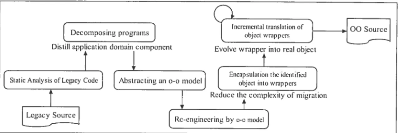
defined in this research. it contains six phases [Luc97] forming the integrated process to gradually migrate legacy code into an object-oriented platfonii:
i Static anctlysis q/Ïegacy code. extract rele\lant information from source code and
store it into a repository. Both fine/coarse-grained information at intra/inter procedural level are recovered.
2. Decomposing non-bcttchprograins: decompose the interface components and the
application dornain components.
. Abstracting an object-oriented model: coarse-grained data-centered entities will
be treated as object candidates, and look chunks as candidate methods. Chunks can be whole batch of programs, subroutines, or groups of related subroutines based on caTi graph or program stice.
4 Re—engineering the svstem according to the resuits of decoinposition ami
abstraction. it’s a modification of each divided source code parts, therefore to
make them more easily to 5e encapsulated in the next stage.
5. Encapsulating the identified objects into wrappers: in this stage, the new object
oriented parts will be able to coexist within the legacy system. The Ïegacy system
or parts of it wifl be encapsulated into an object wrapper and executed on the
original platform. The wrapper provides the interface through which the new object-oriented system can exploit existing resources.
Decomposing programs
J
Distili application dornain e omponent6. Increinentai translation ofobject wrappers: wrapper is a preÏiminary stage of the migration process, thus further object-oriented translation of wrapper will be executed, and different object wrapper will be able to migrate separately.
The kemel part of this approach is the application of wrapping legacy code into an object model during the migration process. Consequently, the original code is essentially entombed and integrated into the new system.
The advantage ofthis approach lies in three aspects: one is that legacy code becomes part of the new generation of the target system without discarding the value of the legacy system; the other one is that the construction of an object wrapper is relatively easier and more rapid than constructing a totally new object entity, it will require less understanding oflegacy code thus reduce the implementation tirne. However, this is also the origin ofits weakness: the quality of the target system will flot be comparable to the pure object oriented one. Finally, wrapping approach enables incrernental migration which benefits a lot from reducing risk and cost by ptogressively conquer the problem.
The shortage also lies in three aspects. First, Iegacy systems, which have evolved over rnany years, are normally difficuit to decompose. Therefore, in rnany cases, applying legacy wrapper technique is quite difficuit. Second, adding wrapping code to encapsulate legacy components increases the migration complexity. Third, extra wrapper communication burden decreases the execution performance, thus reduces the quality of the target system. In a word, wrapping is a compromise approach.
2.3.4 Legacy Wrapping
Wrapping is a method of encapsulation that provides welÏ-defined interfaces to access legacy systems [Sne98]. The major part ofthe legacy wrapping approach is encapsulating certain legacy code fragments into a component-like software entity. Such an entity will be designed with an object interface through which the objects can interact with each other or with the rest of the legacy system. It is a realistic approach, since it is
accomplished easily and rapidly with current available legacy code. Wrapper object makes new systems able to exploit existing resources of legacy systems, thus allowing an incremental and selective translation ofthe identified objects [Luc97]. To use wrapping, application developers must implernent the interface towards subject legacy systems
[LucOO]. Since there are rnany styles of interfaces between subject and target systems, the
communication layer between legacy code and target code is the primary concem. There are two directions of Iegacy wrapping:
u Using a wrapping entity at an intermediate stage of migration process. The ultimate target system will be derived from the wrapped components. The encapsuÏated object entity in fact is flot a resuit ofreal object-oriented design, it is an interim stage that works as a pseudo-object. During the migration process, a wrapping component plays a role as an object meta-model and further object derivation will be perforrned later.
u Using a wrapper as a final result. Thus the target system vill use it as an object oriented component part in the target system, especially in the distributed computing environment [LiOO] [KirnOOj.
The process of wrapping involves different techniques depending on the accessible elernents of a legacy system. ldeally, the Iegacy system has a clean API and weIl documented services. It is then possible to define a direct wrapper interface that should be rninimally affected when any change occurs [LiOO].
Since each tegacy system presents a unique constrained entity, it may have no APIs at
all, or a limited API, or an extensive but proprietary API. Similarly, the legacy system
may use sockets, RPCs, files, events, or any other number of message passing and inter process communication mechanisms. The object wrapper therefore hides these idiosyncrasies and presents an interface that: is consistent with the desired target software architecture.
The wrapping technique can be ftirther classified into five different levels, namely, job process level, transaction level, program level, module level, and procedure level [Sne9$]. At the process level and the transaction level, wrappers encapsulate a batch of legacy executive processes. Legacy applications are invoked through wrappers by creating the requested new process and directly deploying the corresponding service
without prior knowledge of the conesponding legacy code [KimOO]. At the module level and the procedure Ïevel, encapsulation focuses on clear interfaces, restructured and re moduÏarized legacy code. An object wrapper acts as a layer that maps one form of application program interface (API) to another. The layering can be donc without rnodifying the underiying API design. The functionaiity of the layer interface depends on the existing underiying Iegacy system. Meanwhile, additionai functionaiity can be added to the legacy system by enhancing the wrapper layer [Cim9$]. Object wrappers can be categorized into following types: i) wrappers for legacy data; ii) wrappers for legacy functionality; iii) wrappers for legacy presentation logic modules.
Wrapping [egacy Data. Wrapping involves the addition of “layering” code to provide transparent access to legacy databases, relational databases, and flat files [Can99]. It encapsulates the data elements from legacy database or flat file entities as objects and provides interpretation mechanisms between legacy data resource requests and object APIs.
Wrapping Legacy functionality. Object wrappers encapsulate parts of Iegacy code that implernents specific legacy system functionatities. The encapsulation can be arranged at different levets of abstractions, including process level, transaction level, program level, module level, and procedure level [Sne98]{LiOOJ. Encapsulation separates the interface from implernentation. It can then be used to partition and modularize a monolithic legacy system [KimOO]. Each component can be encapsulated separately by the common interface, and then it can be reintegrated using an integrated communication rnechanism used by the target 00 system.
Wrapping Legacy Presentation Logic. In some cases, object wrapping of legacy modules related to the presentation logic may be the oniy option avaitable to integrate legacy applications that are very old and non-decomposable [LiOO]. BasicalÏy, the object wrapper is a layer on top of the screen scraper, which allows client applications to simulate the terminal keyboard/display features and thus acts as programmable terminal emulators. The object wrapper must include interfaces for ail information that the user