by
Wilmar PEREZ
THESIS PRESENTED TO ÉCOLE DE TECHNOLOGIE SUPÉRIEURE
IN PARTIAL FULFILLMENT FOR A
MASTER’S DEGREE WITH THESIS IN INFORMATION TECHNOLOGY
M.A.Sc.
MONTREAL, AUGUST 31, 2018
ÉCOLE DE TECHNOLOGIE SUPÉRIEURE
UNIVERSITÉ DU QUÉBEC
BY THE FOLLOWING BOARD OF EXAMINERS:
Mr. Jean Marc Robert, Thesis Supervisor
Department of Software and IT Engineering, École de technologie supérieure
Mr. Patrick Cardinal, Co-supervisor
Department of Software and IT Engineering, École de technologie supérieure
Mr. Michel Kadoch, President of the Board of Examiners
Department of Electrical Engineering, École de technologie supérieure
Mr. Mohamed Faten Zhani, External Independent Examiner
Department of Software and IT Engineering, École de technologie supérieure
THIS THESIS WAS PRESENTED AND DEFENDED
IN THE PRESENCE OF A BOARD OF EXAMINERS AND THE PUBLIC
ON AUGUST 15, 2018
tenacity: because I own you all. Many thanks.
I am especially grateful to my research director, Jean-Marc Robert. Without his clear guidance I would have never been able to structure this thesis properly. He helped me understand how to focus on what was relevant, he made me appreciate the importance of detail and accuracy in scientific research. I am also very grateful to my co-director, Patrick Cardinal, who was always generous enough to share his research experience and ideas.
To my girlfriend, my wife, Elsury who has been my soul partner through this journey. She has had enough patience to deal with my irritating mood changes and whining during the last couple of years.
I am extremely lucky to have always been surrounded by the most special group of women, my sisters, my unconditional cheerleaders: Lorena, Natalia and Luisa. They are my inspiration for trying to be a better person every day.
I am always grateful, to my friend, my brother, Julio. He was the one that first awoke my interests into the engineering world. A very special gratitude to my partner and friend Mauricio who has dared to dream with me in becoming technology entrepreneurs. A recognition to Pablo and Javier who have showed me the way to be a good professional.
I cannot sufficiently express my gratitude to all those special people that have believed in me: my life-coach Carlos Estrada, my dearest friend Oscar Restrepo, my uncles Mario and the late Dario, and, last but not least, my step-father Rodrigo.
Special gratitude goes to the teams I have worked with at Nuance and Avaya for introducing me into the world of corporate technology business.
RÉSUMÉ
Au cours des dernières décennies, les technologies biométriques sont devenues un important domaine de recherche pour l’industrie de la sécurité informatique. Néanmoins, le déploiement de ces technologies dans des systèmes d’entreprise hétérogènes est complexe compte tenu du manque de standardisation. Le SIP est un protocole de signalisation répendu qui est largement utilisé pour les communications vocales sur des réseaux internet. Grâce à sa flexibilité, SIP a été adopté à grande échelle pour les systémes de téléphonie. Ce mémoire propose SIPBIO, une extension du SIP, qui permet d’établir et contrôler les sessions multimédias utilisant les interactions biométriques.
Le premier chapitre ce mémoire a pour but d’explorer les techniques qui permettent de véri-fier l’identité des personnes par la reconnaissance des caractéristiques intrinsèques de l’être humaine afin d’avoir accès aux ressources du réseau. Notablement, ce chapitre présente une description claire de l’utilisation de la biométrie dans les réseaux de télécommunication. Le deuxième chapitre montre une introduction du protocole SIP en mettant l’accent sur la com-pression de ses messages et ses composants. Le troisième chapitre donne une introduction de nouveaux concepts telle que les extensions du protocole par défaut.
Le chapitre quatre et cinq de ce mémoire présente la base de travail pour la mise en œuvre du protocole SIPBIO. Le chapitre quatre présente une description détaillée des exigences requises pour SIPBIO en utilisant des scénarios typiques pour les opérations biométriques. Ce chapitre fournit une définition du processus formel pour SIPBIO. Le chapitre cinq présente une défi-nition de tous les en-têtes et les composants du corps de SIPBIO qui donnent sa forme et qui définissent sa nature. Finalement, le chapitre six montre une simulation du protocole.
Les résultats de ce mémoire confirment la viabilité de l’utilisation d’un protocole basé sur SIP pour l’instauration, la maintenance et le démontage des sessions multimédias avec des objectives concernant à la biométrie.
Mots clés: SIP, Biométrie, sécurité du réseau, authentication à distance, protocole de commu-nication
ABSTRACT
During the last few decades biometric technologies have become an important research field in computer security. Their deployment, however, in heterogeneous enterprise systems, is com-plex due to the lack of standardisation. Session Initiation Protocol (SIP) is a popular communi-cation protocol widely used in voice over Internet protocol networks; due to its flexibility, SIP has been broadly adopted in telecommunications for carrier level and telephony systems. This thesis proposes the use of SIPBIO, an extension to SIP, to establish and control multimedia sessions for biometric interactions.
For biometric usage in telecommunications networks, a synthesis of techniques to use hu-man characteristics as challenge tokens for access to network resources is first presented. An overview of the SIP protocol is then exposed, by focusing on understanding SIP messages and their component elements. Posteriorly, advanced concepts, such as extensions to the default protocol are introduced.
After the technology background review, the core of the proposal is presented with extensive use-case scenarios of biometric operations and the introduction of necessary SIPBIO require-ments. Formal processes are defined along with the method to extend SIP to the proposed SIPBIO protocol. It follows a detailed outline of all headers and body components that give form to SIPBIO and define its nature. These stages provide the fundamentals for the protocol implementation.
Finally, simulations of some common cases are presented to show the feasibility of SIPBIO. This can be used as a sample flow for full implementations and applications.
This thesis corroborates the viability of using a SIP-based protocol for establishing, maintain-ing and tearmaintain-ing down biometric multimedia sessions.
Keywords: biometrics, SIP, network security, remote authentication, communication proto-cols
INTRODUCTION . . . 1
CHAPTER 1 BIOMETRIC AUTHENTICATION IN TELECOMMUNICATION NETWORKS. . . 5
1.1 Basic biometric architecture . . . 6
1.2 Interpretation of biometric results . . . 8
1.3 Literature review . . . 10
1.3.1 Interoperable framework for biometric communications . . . 10
1.3.2 IDM3G, identity management protocol . . . 11
1.3.3 Voice Interactive Personalized Security . . . 12
1.3.4 BIO3G protocol . . . 13
1.3.5 Securing biometric templates transmission . . . 14
1.3.6 Related projects . . . 15
CHAPTER 2 SIP REVIEW . . . 19
2.1 SIP Requests . . . 24
2.2 SIP Responses . . . 25
2.3 SIP extensions . . . 39
2.3.1 SIP extensions guidelines . . . 39
2.3.2 Representative SIP extensions . . . 42
2.3.2.1 SIPREC . . . 42
2.3.2.2 SIP Extension for payments support . . . 46
2.3.2.3 Other SIP extensions . . . 50
CHAPTER 3 REQUIREMENTS AND USE CASES . . . 53
3.1 Canonical biometric process . . . 53
3.2 Use case scenarios . . . 58
3.2.1 Scenario 1: One-time Active Voice Biometrics authentication (OTAVB) . . . 60
3.2.2 Scenario 2: One-time Passive Voice Biometrics authentication (OTPVB) . . . 62
3.2.3 Scenario 3: Discrete Intervals Passive Voice Biometrics authentication (DIPVB) . . . 62
3.3 Simplified biometric distribution . . . 64
3.4 Extended distribution . . . 66
3.5 Requirements . . . 70
3.6 Extending SIP . . . 71
CHAPTER 4 SIPBIO, EXTENDING SIP AND SDP TO SUPPORT BIOMETRIC
AUTHENTICATION . . . 75
4.1 SIP option-tags . . . 75
4.2 SIPBIO application content . . . 76
4.3 Extending SDP . . . 78
4.4 SIPBIO process . . . 80
4.4.1 Pre-session establishment . . . 80
4.4.2 Session initiation . . . 84
4.4.3 Three way handshake completion . . . 87
4.4.4 Media session and termination . . . 87
4.4.5 Multiple alternative payloads . . . 88
4.4.6 Multiple concurrent payloads . . . 91
4.4.7 Status updates . . . 91
4.5 Mandatory methods header fields . . . 93
4.6 SIPBIO limitations . . . 97
4.7 Closing summary . . . 98
CHAPTER 5 SIMULATION AND TESTS . . . 99
5.1 Preparation . . . 99
5.1.1 Selection criteria . . . 99
5.1.2 Environment . . . .100
5.1.3 Test environment layout . . . .102
5.1.4 SIPp theory and usage . . . .102
5.2 Test scenarios . . . .107
5.2.1 Base test scenario . . . .107
5.2.2 Test scenario with partial results notifications . . . .115
CONCLUSION AND RECOMMENDATIONS . . . .121
APPENDIX I LIST OF ABBREVIATIONS AND ACRONYMS . . . .125
Figure 1.1 Basic biometric process. . . 7
Figure 1.2 EER curve. . . 9
Figure 2.1 Basic SIP Communication. . . 20
Figure 2.2 SIP Basic Trapezoid. . . 20
Figure 2.3 B2BUA. . . 23
Figure 2.4 Three-way handshake. . . 28
Figure 2.5 Basic SIP Message Exchange.. . . 29
Figure 2.6 Basic SIP Trapezoid. . . 29
Figure 2.7 Physical Diagram (Bob and Alice). . . 30
Figure 2.8 SIP Flowfor Alice and Bob (Bob Side). . . 31
Figure 2.9 SIP INVITE (Bob to Proxy). . . 31
Figure 2.10 SIP Trying (Proxy to Bob). . . 32
Figure 2.11 Authentication Request (Proxy to Bob).. . . 32
Figure 2.12 Request Acknowledgement (Bob to Proxy). . . 32
Figure 2.13 SIP Invite with Authentication (Bob to Proxy). . . 33
Figure 2.14 SIP Trying response (Proxy to Bob). . . 33
Figure 2.15 183 Session in Progress (Proxy to Bob). . . 34
Figure 2.16 SIP INVITE (Proxy to Alice). . . 34
Figure 2.17 SIP Trying response (Alice to Proxy). . . 35
Figure 2.18 SIP Ringing (Alice to Proxy).. . . 35
Figure 2.19 SIP OK (Proxy to Bob). . . 36
Figure 2.21 OK (Alice to Proxy). . . 37
Figure 2.22 ACK (Proxy to Alice). . . 37
Figure 2.23 SIP Dialog termination (Bob to Proxy, Proxy to Bob, Proxy to Alice, Alice to Proxy). . . 37
Figure 2.24 B2BUA as SRC. . . 44
Figure 2.25 UA as SRC. . . 45
Figure 2.26 SRC initiated recording. . . 45
Figure 2.27 SRS initiated recording. . . 46
Figure 2.28 Simple Payment Process. . . 48
Figure 3.1 Biometric process flow . . . 54
Figure 3.2 Biometric process sequence diagram . . . 55
Figure 3.3 Classic enrolment / verification sequence - active biometrics. . . 61
Figure 3.4 Classic enrolment / verification sequence - passive biometrics. . . 63
Figure 3.5 Biometric flow condensed. . . 65
Figure 3.6 Biometric flow with associated HTTP APIs. . . 66
Figure 3.7 Naming equivalence for biometric actors. . . 66
Figure 3.8 Extended distribution active biometrics example. . . 67
Figure 3.9 Extended distribution passive biometrics example. . . 69
Figure 4.1 SIPBIO simple session. . . 89
Figure 4.2 SIPBIO simple session (off band media). . . 89
Figure 4.3 SIPBIO multiple choices / one stream. . . 90
Figure 4.4 SIPBIO multiple choices / multiple streams. . . 92
Figure 4.5 SIPBIO with updates. . . 93
Figure 5.2 Test scenario 1.. . . .108
Figure 5.3 Test scenario 1, associated trapezoid. . . .108
Figure 5.4 Test scenario 1, OPTIONS. . . .108
Figure 5.5 Test scenario 1, 200 OK to OPTIONS.. . . .110
Figure 5.6 Test scenario 1, INVITE.. . . .111
Figure 5.7 Test scenario 1, 200 OK to INVITE. . . .112
Figure 5.8 Test scenario 1, ACK. . . .113
Figure 5.9 Test scenario 1, BYE. . . .114
Figure 5.10 Test scenario 1, 200 OK to BYE. . . .114
Figure 5.11 Test scenario 2.. . . .115
Figure 5.12 Test scenario 2, associated trapezoid. . . .116
Figure 5.13 Test scenario 2, SUBSCRIBE. . . .116
Figure 5.14 Test scenario 2, NOTIFY (partial result 1). . . .118
Figure 5.15 Test scenario 2, NOTIFY (partial result 2). . . .119
Figure 5.16 Test scenario 2, NOTIFY (Final result). . . .119
Figure 5.17 Test scenario 2, Un-SUBSCRIBE.. . . .120
the lack of security in computer systems. A combination of early design decisions and com-mercial interests led to the release of a plethora of products flawed by poor security practises. A common approach to cyber threats has been to make it very cumbersome for users to access a computer system. This approach has taken various forms: long, complex and difficult to remember passwords; token-based security, where a trusted third party guarantees the authen-ticity of the parties and the integrity of the data being exchanged; geographical and IP-based access restriction, among others. The combination of these techniques makes it difficult for an attacker to access non-authorised information. However, this approach has also made it diffi-cult for legitimate users to use resources they are entitled to. The academics, and a sector of the industry, have worked in the development of secured easy to use systems. However, many of the proposed systems are still highly complex for the regular user, requiring a level of user participation that is not easily achievable. In the last two decades, two technologies have gone through dynamic trends of development and investment:
• Biometric technologies. A way of identifying people by a combination of what they are
and what they know (Jain et al., 2016).
• SIP communications. A technology to standardise signalling between parties who need to
exchange media information (Rosenberg et al., 2002).
Biometric technologies have extensive security applications while SIP powers the develop-ment and enhancedevelop-ment of products, notably, those related to telephony over Internet Protocol networks.
Both of these fields have reached technological maturity. Biometric authentication is a proven and accepted way to recognise individuals and grant them access to systems of information
(Beranek, 2013). SIP is the accepted standard for establishing multimedia sessions (Sisalem
et al., 2013).
This thesis aims to contribute to the development of comprehensive, flexible, and secured sys-tems, which are easy to implement and understand. This thesis argues that it is possible to leverage SIP properties to create a common session establishment protocol for sessions that require biometric authentication. By using an already trusted protocol, vendors can provide standard solutions to include biometric-based authentication, and access control, across net-work elements. They will know that their solution can be easily integrated with other elements of a system supporting the same standard. These solutions can be proven to be simpler for the end user. They benefit by accessing resources using their own biological properties as an authentication token. The approach could be as simple as associating a user’s voice with a standard user identifier, which would require the user to speak in their normal voice or to re-peat a simple predetermined phrase. An interaction of this kind is easier than typing a long and complicated password. An extension to the SIP protocol, called SIPBIO is proposed to handle the tasks of establishing a biometric session.
Chapter 1 reviews the history and development of using biometric methods in telecommunica-tions networks. Several earlier proposals are identified and analysed in the context of their own time and for their contribution to most recent technological developments. Chapter 2 reviews the basic concepts of the SIP protocol in preparation for Chapter ?? which presents relevant SIP canonical extensions. The aim of this analysis is to reveal how SIP is extended in prac-tice and how these previous extentions can be applied to the SIPBIO proposal. In Chapter 3 the evaluation methodology is explained in detail, starting with some test case scenarios. This information will lead to building SIPBIO requirements that serve as the base for the protocol construction later. Finally, the process of extending SIP is explained in detail.
Chapter 4 presents how SIPBIO can be used to handle different types of biometric processes, and the core of the protocol, its flows and SIP messages. Chapter 4 is the core of this proposal. The concepts are reinforced in Chapter 5 with a simulation of a protocol implementation.
Finally, the conclusions are presented along with suggestions for extended developments around the SIPBIO proposal.
This thesis is motivated by fifteen years of telecommunications experience in the field, work-ing with customers in need of solutions, practical and easy to understand, for security and communication challenges.
The idea of using biometric techniques to authenticate users in telecommunications has been around for many years as a theoretical, yet cumbersome to implement, possibility (Lapere and John-son, 1997). Recent increases in computing power, data transmission speeds and the availability of affordable storage, now make viable the use of biometrics in enterprise and consumer-based telecommunications (Gafurov, 2010).
The definition of a telecommunications network derives from the concepts of computer
net-works and distributed systems. According to Tanenbaum and Wetherall (2011a), a computer network is a collection of autonomous computers (nodes) interconnected by a single
technol-ogy and a distributed system is a collection of independent computers that appear to their users as a single coherent system. Consequently, a telecommunications network can be defined as a distributed system in which nodes are either computing entities or computer networks and offers services related to information sharing.
The above definition determines that the main objective of telecommunications is to share or allow access to information through or from any kind of voice or data network. Information can take any form, including documents, audio, voice and video. Some information is intended to be openly available, such as websites on the Internet. Other information is restricted to a single party like a personal bank account web site or phone line or to a specific group of people as with a corporate intranet. Different mechanisms have been developed to control access to shared resources, which use passive or active authentication by the user sharing the resources (Mallery, 2013).
When telephonic communications were controlled by public providers, security was main-tained by their exclusive access to all hardware. As networks evolved to packet and mobile-based technologies access was controlled by a personal identification number (PIN) and, in the case of mobile telecommunications, a smart card in the form of a Subscriber Identification
Module (SIM). These solutions are convenient but lack security (Lapere and Johnson, 1997).
Any telecommunications access control measure must meet the following requirements:
a. be simple to use yet effective enough to provide a noticeable level of security;
b. be measurable, recorded and quantifiable (Eur, 1997).
These are also characteristics of a biometric security system.
Biometric characteristics for authentication in telecommunications environments have been ex-plored since the 1990s when the European Telecommunications Standards Institute (ETSI)1, made it a priority to provide secure communications standards for UMTS. They stated, "with-out a reliable authentication service through the Telecommunications Management Networks (TMN), every other effort to secure the system is in vain" (Eur, 1997). In the 1990s, there were obstacles to use biometric authentication methods: sensors were costly, processing power was low, service provider charges for data transmission were very high, acceptance and use of the technology were challenging. In the particular case of voice biometrics, telephones al-ready had audio capturing sensors and they were a familiar device, making them a viable and non-intrusive option.
1.1 Basic biometric architecture
Communication network biometric systems are known as remote biometric authentication
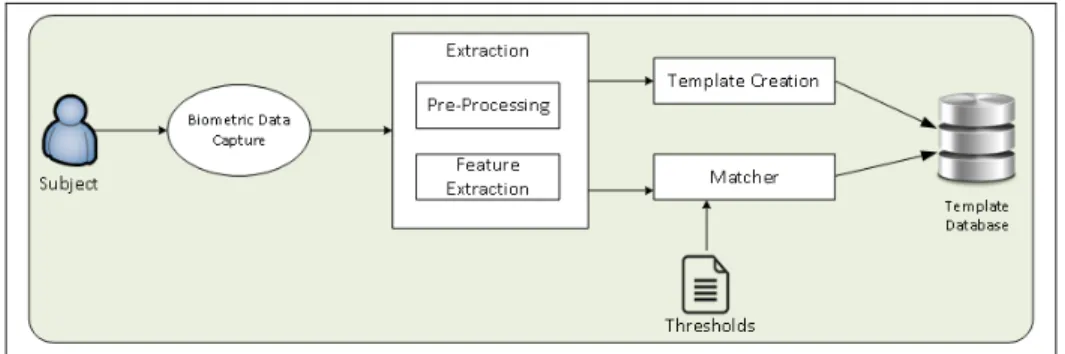
sys-tems (Syta et al., 2015). A general architecture of a biometric system is shown in Figure 1.1.
The set of relevant elements shown in Figure 1.1 are described by Gafurov (2010):
• A subject from whom the biometric information is read.
Figure 1.1 Basic biometric process.
• The biometric data capturing process. This is accomplished by one or more
mechani-cal or electrimechani-cal objects that capture raw data to be analysed. The usual objects are mi-crophones, webcams, mobile phones (which have several capturing methods), fingerprint readers, keyboards, mouse devices. A capturing element does not have to be a device specifically designed for biometric operations. A finger print reader has been specially designed for biometric data capture whilst a telephone has not. In general, any device able to retrieve biometric data and retransmit it in a digital format can be considered a capturing
element.
• Database: Once a template is created, it is stored in a database. During a verification
process, the matcher retrieves the claimed user template from the database and compares it with the one obtained from the feature extractor.
• The extraction process of finding the digital representation biometric data. It is as a
two-step process:
• Pre-processing: Before being digitized, the raw data set is pre-processed to assess its
quality. It is then segmented and enhanced. A quality assurance process for the raw data set is necessary to determine if more sets of biometric data are to be collected. Segmentation is mainly the process of separating actual biometric information from the background model. Finally, the raw data set is enhanced to improve its quality and reduce signal noise.
• Feature extractor: Pre-processed biometric information is digitized to create a
biomet-ric template. This template is expected to have unique individual information. This step is functionally merged with the template creation and matcher processes. For a new biometric speaker, the product of the feature extractor is used to build their biometric template. In the case of an existing speaker, the product is used to create a temporary digital representation of the captured biometric payload to be compared against their existing stored template.
1.2 Interpretation of biometric results
In telecommunications networks, as in biometric systems, the tradeoff between False Accepts (FA) and False Rejects (FR) is an ubiquitous problem. During an authentication process a stored biometric print is compared against the results of a live feature extraction process as shown in Figure 1.1. When an imposter is authorized, it is called a False Accept. When the authentic user is denied access, it is known as a False Reject. The probabilities of these events happening are, correspondingly, False Accept Rate (FAR) and False Reject Rate (FRR) (Reid, 2003a). These two rates should be as close to zero as possible. Figure 1.2 shows a distribution of authentication events for a general population. This representation is commonly known as an Equal Error Rate (EER) curve. Biometric implementations set thresholds to balance high security with convenience of use. The more secure the system, the higher the likelihood of a FR event. The more convenient the system, the higher the probability of a FA event. Note that the curves in Figure 1.2 are not normal distributions but simply a generalist representation of the expected number of reject and accept events.
Defining the following events:
• Impostor: a fraudster. • Authentic: authorized user.
Figure 1.2 EER curve.
• Positive Result: a result of a biometric operation giving the provider of the bioprint as the
authentic user.
Each event can be true or false. For instance, whether an Impostor is actually a fraudster or not. The result depends on several factors, mainly, the algorithm itself and the quality of the training set (data use to tune the system).
The EER distribution, inferred from a formulation of the Bayes’ theorem (Lee, 2012), would take the form shown in Equation 1.1
P(Impostor|positiveResult)=P(positiveResult|Impostor)×P(Impostor)+P(Authentic|!Impostor)×P(!Impostor)P(positiveResult|Impostor)×P(Impostor) (1.1)
where:
P(!Impostor)=1−P(Impostor)
and:
• P(Impostor | Positive Result): the probability of the bioprint belonging to an impostor given
that the result of the operation was positive.
• P(Positive Result | Impostor): the probability of having a positive result in the operation
given that the bioprint provider is an impostor.
• P(Authentic | !Impostor): the probability of the operation yielding a positive result given
that the bioprint provider is not a fraudster (it is the true user).
• P(!Impostor): the probability of a bioprint provider not being a fraudster (being the true
user).
In general, Equation 1.1 can be interpreted as the probability of obtaining a positive result when the bioprint provider is an authorized user divided by the probability of obtaining a positive result in the operation regardless of the nature of the provided bioprint.
1.3 Literature review
Several identity management systems for secure authentication have been proposed. This sec-tion reviews not only some of those systems but also some previous studies that made them possible.
1.3.1 Interoperable framework for biometric communications
It was once unsafe and expensive to perform remote authentication on telecommunications net-works, so the focus of early biometric authentication was on local authentication. Here, remote authentication refers to a system where the subject and the biometric capturing mechanisms are in a different local area network (LAN) to that of the rest of the biometric system as rep-resented in Figure 1.1. This situation made biometric authentication technique impossible in practice. With the availability of higher bandwidth and the development of traffic encryption techniques, the possibility of using remotely distributed processing power and storage became a more acceptable option (Benavente and Piccio-Marchetti, 2005).
Biometric implementations must be inherently secured. Security of communication paths and data repositories must be mandatory. Benavente and Piccio-Marchetti (2005) proposed the en-capsulation of the whole communication path during the biometric interaction, suggesting a
biometric functions, the second is another API to access biometric information in the form of a token, which is as a pattern provided for comparisons, and the third component is a fusion layer that exposes a common interface to third-party applications using a given framework. The second API performs matching between the protocols. Each module uses encryption and authentication protocols in the form of Extensible Authentication Protocol (EAP) over a
Trans-port Layer Security (TLS) tunnel. Further details are not discussed because more suitable
approaches have been proposed since. However, this contribution was important in raising awareness about the security challenges faced by biometric authentication methods when used over communication networks.
1.3.2 IDM3G, identity management protocol
Dimitriadis and Polemi (2006) propose a detailed identity management protocol (IDM3G) for Internet applications over 3G mobile networks. This protocol combines the identity manage-ment principles of the former Liberty Alliance specification (currently Kantara Initiative)2with those of the Organization for the Advancement of Structured Information Standards (OA-SIS)3 and the 3rd Generation Partnership Project (3GPP) 4. This proposal seeks to provide a lightweight identity management system. Its relevance is linked to three key concepts re-quired for any authentication protocol: security assessment, performance and implementation complexity. Dimitriadis and Polemi (2006) use the same Authentication Key Agreement (AKA) mechanism of the Universal Mobile Telecommunications Systems (UMTS), which is the formal extension of the PIN/SIM combination previously mentioned. IDM3G specifies four entities: user (U), User’s SIM (USIM), Mobile Operator (MO) and Service Provider (SP). The logic of the protocol is based on the transmission of a random token from U to SP. The same token is then forwarded by SP to MO, which will use it to determine which voice and data services to provide to U. IDM3G assumes that there is already a trust relationship between MO and SP in which the identity of U needs to be assessed using alternative methods (including but
2 kantarainitiative.org 3 www.oasis-open.org 4 www.3gpp.org
not limited to biometric authentication). IDM3G also assumes that between the USIM and the MO there is a mutual UMTS-AKA mechanism to guarantee the identity of the parties. The technical details of the IDM3G protocol are beyond the scope of this document, however, it can be summarised as follows:
a. USIM request a service on behalf of U, who has been previously authenticated.
b. USIM provides proof of identity to MO.
c. SP requests MO to verify the USIM identity.
d. MO certifies the USIM identity based on matching of the two pieces of information, the one sent by SP and the one previously sent by USIM.
IDM3G was evaluated in terms of performance, implementation complexity and security (the third, security, against guidelines established by the Internet Engineering Task Force (IETF)5. SIPBIO uses similar guidelines to be explicated in Chapter 3.
1.3.3 Voice Interactive Personalized Security
Another interesting proposal for the use of biometrics for telephony environments was the Voice
Interactive Personalized Security (VoIPSEC) protocol presented by Kopsidas et al. (2006).
VoIPSEC attempts to provide end-to-end secured communications with the use of inbound key exchange and biometric verification. Through analysis of VoIP communication patterns over the Internet, the authors concluded that an end-to-end encryption between the parties was the only way to offer full communications confidentiality. VoIPSEC was intended to provide such a mechanism in three phases. The first phase consists of the generation of constituent components:
a. A private key, a public key and a User Session Signature (USS) for each party. The USS has a particular property: it can be any binary object that the party prefers to use (e.g. an email address, a video, etc.).
b. A symmetric session key to be used during the communication between both parties.
In the second phase, the communication parties were to exchange the symmetric session key and their respective USS. In the third phase, the USS was to be biometrically verified. This biometric action could be of level 1 (only voice) or level 2 (voice and video). If any partici-pant were not successfully verified, both communication parties were to be notified. It is up to the application using the protocol to define if it makes the authentication compulsory or if it gives the participant the option to continue opening the communication channel after an unsuccessful verification. The security of the protocol depends heavily on the USS and the symmetric session key exchanged by the participants before any information was to be trans-mitted. This behaviour is quite similar to a registration process. Research literature suggests that the VoIPSEC proposal has not been adopted. It may be because it appears rather com-plicated and no canonical implementation is freely available. However, the use of biometric data as part of an authentication process makes VoIPSEC an interesting alternative: it uses the biometric information to secure itself.
1.3.4 BIO3G protocol
Another attempt to create a biometric based authentication protocol was presented by Dimitri-adis and Shaikh (2007) with their BIO3G protocol proposal for Third Generation (3G) mobile systems. This was an extension of what was commented on above and presented by Dimitri-adis and Polemi (2006). Unlike VoIPSEC, BIO3G does not enroll users or transfer any data across the data network. The aim of BIO3G is to provide PIN-less authentication between an end user and a mobile operator using only biometric techniques, without the need for biomet-ric enrolment. BIO3G still uses the same network access authentication mechanism of UTMS, UMTS-AKA, as its core authentication element.
The logic of the protocol is as follows: during the first interaction between the user and the mobile operator (e.g. when the mobile phone is turned on for the first time or when the mobile radios are enabled) the end user provides some sort of biometric material (possibly a voice sample) to the phone (specifically to the SIM) which calculates a key k; the key is sent to the mobile operator which produces a new key k based on the one received from the SIM; the mobile operator sends back k to the SIM. From that point forward, any time the user wants to make a call, they will provide a biometric sample that will be used by the SIM to locally generate k that will be used by UMTS-AKA to authenticate the SIM against the mobile operator (Dimitriadis and Shaikh, 2007).
BIO3G is an interesting approach that addresses some problems of the authentication biometric techniques: storage of biometric material (i.e. it does not store any). However, BIO3G also faces some difficulties. Variable quality of biometric material can yield a non-compatible key for subsequent user authentication, the limited processing power on some phones being the cause. However, due to the development of authentication techniques and the capacity of cur-rent mobile phones, those limitations are less relevant compared to when BIO3G was proposed more than ten years ago. Dimitriadis and Shaikh (2007) evaluate the compliance of BIO3G using formal process algebra Communication Sequential Processes (CSP) (Hoare, 1978) and
Rank Functions (Schneider, 1998).
1.3.5 Securing biometric templates transmission
Biometric features for authentication over communication networks, such as an individual’s biometric print (template), may be stolen either in transit or from the system database. Several solutions have been proposed to address this concern. BIO3G completely avoids both trans-mission and remote storage of biometric prints (Dimitriadis and Shaikh, 2007). Kikuchi et al. (2010) proposed the use of a zero-knowledge proof protocol, which allows a user to prove that they have some valid piece of biometric data, without actually revealing it. They proposed two protocols to achieve their purpose: The Private-Cosine and the Private-Euclid based on the cosine correlation and the Euclidian distance respectively. With reasonable computational
resources, both protocols allow remote authentication without revealing any private data. In terms of accuracy, the biometric results are not satisfactory, however, for the purpose of this literature survey we are only interested in the description of a feasible secure remote biometric authentication. Kuseler et al. (2010) proposed a layer authentication architecture,
eBiomet-rics, to be implemented as an application on mobile phones. eBiometrics pretends to be an
application that offers authentication services to other applications through the control of all matching sensors (e.g. camera, fingerprint reader and microphone). eBiometrics would pre-process, analyse and deliver results on raw biometric pieces of information. It can be either implemented as a local (on the mobile phone itself) self-contained system or as the client of a hosted application.
Johnson et al. (2014) presented a different approach to the issue of compromised biometric templates. Their proposal is based on the concept of vault verification introduced by Wilber
et al. (2012), which consists in separating the biometric template into several pieces,
scram-bling them with fake pieces of biometric data and then putting them back together. The ob-jective is to obfuscate the real information making it very difficult for an attacker to identify the authentic data in the biometric template. Subsequently, in similar papers, Wilber and Boult (2012) and Johnson et al. (2014) argued that in the context of voice authentication over re-mote networks, even if the biometric template is stolen, the risk of a successful attack can be minimised by using random authentication with short phrases as a complement of the main authentication process. They also proposed to add random pass phrases to the real template in order to use them to confirm the identity of the true speaker. This technique has the added value of mixing text dependent (a pass phrase) and text independent (a random phrase) audio responses that may mitigate reported vulnerabilities of both text dependent and independent approaches.
1.3.6 Related projects
Finally, to close this review, several authors developed approaches to solve different aspects of the problem of secured remote biometric authentication over communication networks. These
proposals were not reviewed extensively to avoid making this chapter overly long. The reader is invited to explore the original articles for further details.
• Li and Hwang (2010) suggestd the use of one-way hash functions, biometric verification
and smart cards.
• Agbinya et al. (2011) proposed a Multimodal Identity Management System that fuses
fin-gerprints and face recognition using neural networks based biometric techniques.
• Xi et al. (2011) proposed a client server biometric authentication protocol oriented to
mo-bile environment; it uses encrypted fingerprints (based on Elliptic Curve Cryptography) and a Public Key Infrastructure (PKI) to protect biometric authentication sessions through insecure mobile networks.
• To avoid user information to be extrapolated from biometric data (e.g. genetic information
or diseases), Abidin and Mitrokotsa (2014) proposed an enhancement to the privacy
pre-serving biometric authentication protocol (PPBA) proposed by Bringer et al. (2007) using
the Goldwasser-Micali cryptosystem based on homomorphic encryption. They improved the PPBA security by using two secret keys against the system biometric sensor during the verification stage.
• Using homomorphic encryption and a similarity scored based on Squared Euclidian
Dis-tance between the query vector (the analysed biometric verification sample) and the bio-metric print, Wong and Kim (2012) claimed that a biobio-metric verification can be completed without exposing the original data.
• Traore et al. (2014) proposed Behavioural biometrics. A Bayesian network model is
ap-plied to remote keyboard and mouse events to create their particular usage characteristics of a specific user. Their experimentation yields a EER of 8.21% on a limited subset.
• Nomura et al. (2015) took the heartbeat waveform as their biometric measure; they
anal-yse the properties of an electrocardiogram (ECG) to identify a subject with the dynamic variability of the ECG which, reportedly, keeps unique the features of the subject. The
reported positive authentication rate is not that encouraging at around 80%, however, since wearable devices could be adapted to read ECG signals providing a very unique biometric identification, a great potential is seen in this type of approach.
• Saevanee et al. (2015) used multimodal biometrics over mobile networks: linguistic
anal-ysis, key strokes dynamics and behavioural profiling to reach a reduction of 91% in the rate of spoofed authentication. The key element of this study is the demonstration that, even though one single biometric entity may not be trustworthy, the combination of several biometric measures can leverage positive results; furthermore, it opens the door to the pos-sibility of using continuous data entries for an equally continuous authentication through the length of a user-to-user interaction.
All the works mentioned in this chapter focus on characteristics of the biometric process and the process to provide biometric payloads and collect the results. None of them has leveraged an already accepted communication mechanism to facilitate these processes. Next chapter introduces such mechanism to, subsequently, explore its use in biometrics.
Session Initiation Protocol (SIP) is an application layer telecommunications control protocol. It has been designed to handle signalling for multimedia sessions: establishment, modifica-tion and terminamodifica-tion. SIP is used with other protocols, notably the Session Descripmodifica-tion Pro-tocol (SDP), to transport multimedia content (including VoIP, images, video, etc.). SIP can be considered as a framework for the deployment and development of communication services (Rosenberg and Schulzrinne, 2006). SIP provides all actors of a communication exchange with a set of rules for establishing a session. SIP is text-based encoded. In practice this means that SIP is easy to read and understand. Any protocol that SIP uses (e.g. SDP) is expected to have the following features (Martinez, 2008a):
• Clear indication of supported media.
• The availability of the media through the session.
• Transport information for the media itself (IP and port to which the media packets should
be sent).
In its basic form, SIP can be used as a peer-to-peer protocol where endpoint devices (called
User Agents (UAs)) have a high level of autonomy. A complete exchange of data can be
entirely processed between two UAs without the need for any third-party component. Figure 2.1 illustrates the basic building blocks of a SIP communication exchange: each participant is called a User Agent (UA), each UA can take the logical role of a client (UAC)or a server (UAS), the client is the one initiating the conversation requesting something and the server is in charge of replying to that client’s requests (Martinez, 2008a).
As extrapolated from Figure 2.1, UAs are flexible in nature and can take different roles. It is customary to define the SIP functions in two main groups: UA clients (UAC) and UA servers (UAS). An endpoint usually supports both groups of functions.
Figure 2.1 Basic SIP Communication.
In practice UA to UA communications are processed by SIP-aware devices such as proxy servers, soft-switches, SBCs, etc. All intermediate components facilitate services and en-able UAs to communicate over different IP networks. In general, UAs initiate and control dialogs while intermediate devices provide routing and offer extra services. Under certain con-ditions, intermediate devices can also act as UAs. When required, potential confusions are to be avoided by referring to the UAs as SIP clients or servers, where the client is the entity orig-inating the request and the server is the entity receiving and processing the request (Martinez, 2008a).
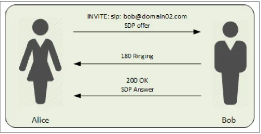
Figure 2.2 illustrates the most basic scenario of a SIP communication establishment between two UAs located in different networks. The initial request is sent by Alice’s UA through her local SIP proxy; this proxy sends the request to Bob’s SIP Proxy (either directly or through intermediate SIP proxies); eventually the request reaches Bob’s UA which reply follows the same logical path backwards to reach Alice’s UA. If everything works as expected, a direct communication is established between both UAs. This scenario is the simplest of the cases. It can very well happen that the proxies are kept in the path of both the signalling and media sessions, or only the signalling goes through the SIP proxies whilst the media establishes direct communication or goes through different proxies specialised in handling the specific payload type (Steffen et al., 2004).
UAs are identified by a SIP Universal Resource Identifier (URI). A SIP URI must conform to the rules established by RFC 3986 and must have enough information to establish and keep a communication session with the UA (Berners-Lee et al., 2005). An example of a SIP URI would be: sip:[email protected].
A SIP URI can be virtually identical to a regular email address. A more generalised description of the SIP URI format would be sip:userID@host:port, where the user ID is an optional com-ponent which uniquely identifies a resource (a user, a group of users, an extension, a service, etc.) and the host is either the Fully Qualified Domain Name (FQDN) or the IP the resource is associated with. Finally, the port is only used when a non-default port is used for the commu-nication establishment. SIP URIs that provide identification to resources to be contacted over a secured channel (e.g. Transport Layer Security (TLS)) change their format to SIPS URI, note the S after the SIP identifier. SIP URIs have other interesting properties such as the generic use of URIs to identify secondary resources for a given already identified resource. For instance, starting from a single URI, a user could be linked to his email, phone number, web site, etc. (Schulzrinne, 2001).
Figure 2.2 shows how a proxy server entity is used to facilitate the communication between two UAs. SIP scenarios include the use of several facilitating entities or servers. These servers are usually named based on their function:
• Proxies: SIP Proxy Servers mainly determine where to send signalling messages (i.e. route
SIP messages). Given their location in the communication path, SIP Proxies also are often given the task of performing authentication and authorisation. A SIP Proxy can participate during call establishment or for the entire length of the call, which would depend on the level of call control desired and the topology of the network. For network to network com-munication the SIP proxy is usually required during the entire comcom-munication. SIP proxies can manipulate SIP headers to redirect or modify the characteristics of an interaction. Each UA needs to be notified of its corresponding SIP proxy or proxies. This notification is usu-ally accomplished by direct configuration or by using network configuration protocols (e.g.
Dynamic Host Control Protocol - DHCP) (Subramanian and Dutta, 2013).
• Location: Location Servers keep track of the current location of all UAs in the system.
They usually keep records of registered clients (i.e. UAs) in a local database. Each record holds an UA ID and its last known network location. A Location Server provides UA location information for other UAs. Note that a location service is not a SIP entity, it is a general service that, as mentioned, keeps records of the UA location without any impact on the SIP signalling or any associated payload. (Ott, 2001)
• Registrar: SIP Registrar Servers are entities that handle the registration of UAs. When
a Registrar server allows a UA request to be registered, it notifies an associated location server that keeps a log of all UA whereabouts. When an UA changes location, it regis-ters through the registrar in the corresponding zone which updates the record in the re-spective location server. UAs periodically send register messages to update their location (Schulzrinne, 2001).
• Redirect: SIP Redirect Servers provide alternative URI information to an UA sending a
auxiliary server in the case of system failure. SIP Redirect Servers do not initiate requests or accept calls which makes them very efficient for handling high loads. However, their use is limited to a very specific set of functions (Osterhout, 2003).
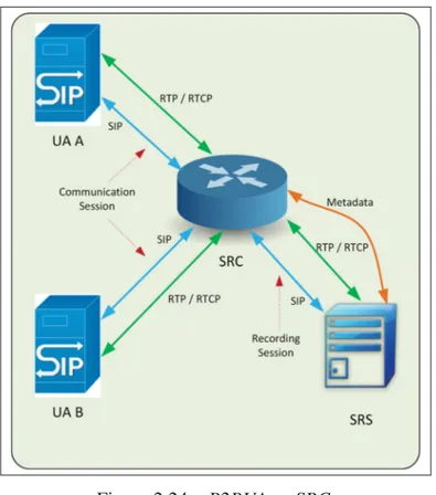
Among the basic SIP entities there is another widely used SIP element known as a
Back-to-Back User Agent (B2BUA). A B2BUA is a special type of SIP entity able to act as a different UA
(UAC or UAS) for both ends of a SIP call. A B2BUA takes a SIP request, processes it following an internal programmatic logic and then creates a new SIP request based on the original one plus relevant programming rules. A B2BAUA can be thought as a pair of UAs linked by a programmed logic. B2BUAs are also known as SIP application servers. B2BUAs are primarily used to modify signalling properties and routing calls based on high-level logic (Zave et al., 2009). Figure 2.3 illustrates the design principle behind a B2BUA.
Figure 2.3 B2BUA.
SIP has become very popular in part because of the formatting of its messages. Unlike other communication protocols, SIP messages are text-based (they use the UTF-8 charset and follow the Internet Message Standard as defined in RFC 2822 (Resnick, 2001)). SIP Messages are classified as requests (UAC to UAS) and responses (UAS to UAC). SIP messages are, in form, similar to the requests and responses of the Hyper Text Transfer Protocol (HTTP) 1.1. as described in RFC2616 (Fielding et al., 1999). However, SIP is not an extension of HTTP; SIP and HTTP simply share the same type of formatting and the same working philosophy of
simplified requests and responses. This proposal is SIP-dependent so to understand what is expected of SIP messages a summary of their main characteristics follows.
2.1 SIP Requests
SIP requests always have three elements: a method name (REGISTER, INVITE, ACK, CAN-CEL, BYE and OPTIONS), a request URI, and the protocol version. In general, the format of a SIP request is Method[ ]Request URI[ ]Protocol version.
For instance, INVITE sip: [email protected] SIP 2.0 is a valid SIP request.
The behaviour of every SIP request depends of the method being used. Most relevant charac-teristics of SIP Requests Methods are shown next.
REGISTER. It is used by the UA to associate its public identity to its current location (contact
address) through a registrar server. The request must include the public identity (e.g. [email protected]) and its current location (e.g. [email protected]).
When the registration process is successful, an entry with the appropriate information is added to the location server. The UA needs to send a new registration request before the time-to-live of the registered entry expires.
INVITE. Due to its flexibility, the INVITE has become the most used SIP request method. In its more basic form, a SIP INVITE is used when a UAC initiates a session. An INVITE request contains the UAC public identity. After an INVITE the UAC expects either a success or a provisional response. The message exchange initiated by an INVITE is known as a SIP DIALOG. The INVITE is also used for the parties to agree on the codecs to use and the IP and ports where media (e.g. RTP) traffic will be exchanged. SIP itself is not intended to be used for media characteristics definition. However, it can carry SDP information as body content. SDP, on the other hand, is specifically designed to describe the media properties of a communication session. (Handley et al., 2006)
A particularly useful SIP characteristic is the possibility of modifying many of the initial dialogue parameters. Within an existing SIP dialogue, a new INVITE can be exchanged between the parties to modify session characteristics (e.g. change media destination). This type of request is known as a Re-INVITE.
Arguably, the INVITE is the most important type of SIP message. It can start a com-munication request and it can be used to modify the parameters of a comcom-munication in progress: change routing, change types of media, add parties to the conversation, etc. For the first communication establishment, an INVITE relies on a SIP proxy service to find the right party and its respective location. A SIP resource can register itself from mul-tiple locations against a given SIP Proxy. A user, for instance, can register a SIP phone on a mobile and a computer at the same time, notifications are sent to both registered endpoints.
ACK. It is a special type of SIP request used by the three-way handshake implemented in the INVITE method. An UA generates an ACK when it receives the final response corresponding to an INVITE.
CANCEL. This request is used to interrupt a pending transaction. Upon reception of a CAN-CEL request the UAS simply acknowledges it with a 200 OK and cancels any pending transaction from the corresponding dialogue. The UAS also notifies the UAC about the cancellation of the original transaction with a 487 response.
BYE. It is mostly used to simply terminate an existing session.
OPTIONS. This request allows a UAC to query a UAS to know of its capabilities (e.g. sup-ported methods, codecs, etc.). The main objective of an OPTIONS request is for the UAC to know how the build a subsequent INVITE based on the actual UAS capabilities.
2.2 SIP Responses
There can be more than one SIP to a single request: one final response and, alternatively, several provisional ones. Responses are identified by a three-digit status code that indicates
the result of a request. The three-digit code is intended to be used as a programmatic guide for SIP-based applications. Status codes are divided in six groups:
• 1xx: Provisional (task in progress.) • 2xx: Success.
• 3xx: Redirection (a different set of actions need to be done to complete the request.) • 4xx: Client error (the request is not valid or is not supported by the server.)
• 5xx: Server error (the request seems to be valid but the server was not able process it.) • 6xx: Global failure
The format of a Response is as follows:
Protocol version /[ ] Status-Code /[ ] Reason phrase -> e.g. : SIP 2.0 200 OK
Header Fields:
Header Fields provide detailed information of requests and responses and their respective body
contents. Each Header Field has a field name, a field value (which may contain an optional dis-play name for visualization purposes) and, optionally, a parameter (field name: Disdis-play Name
<field value>; parameter name = parameter value). The field value is any of the previously
seen requests and responses. A simple example would be:
From: Wilmar Perez <sip:[email protected]>; tag=074e6845296ae42ba
A short description of the mainheader fields is shown below:
TO. It indicates the AOR (logical identity) of the recipient. Notably, the To Header Field is not modified by any intermediate proxy.
CALL-ID. It is an unique automatic identifier to link messages within the same SIP Dialogue.
VIA. It is added by each SIP proxy in the communication path. It indicates the routing path a response needs to follow. It must include the transport protocol used to send the message and the sender network information. It may also have two optional fields: branch to identify messages within the same transaction and received which shows the true origin of a request.
CONTACT. An UA can provide a SIP URI that can be used by other parties to establish future contacts. Since VIA headers can potentially be stripped off when a specific SIP proxy is no longer required in the path, a CONTACT header is a reliable way of keeping the UA information during the whole SIP Dialog.
RECORD-ROUTE and ROUTE. These two headers are used together to force responses to go through a specific route. A SIP Proxy can introduce a RECORD-ROUTE to force future requests in the same SIP dialogue to go through a specific route. When the re-questing UA receives a response with a RECORD-ROUTE request header, it inserts the received value inside a ROUTE header to force subsequent responses to go through a path of specified proxies.
CSEQ (Command Sequence). This header consists of a sequence number and method. The number is used to keep a sequence of end-to-end requests in a SIP dialogue. The method is used to keep a correlation of requests and responses within the same transaction.
MAX-FORWARDS. The Max-Forward Header defines the maximum number of proxies that a request can traverse to get to its destination.
There are additional relevant headers and characteristics of the SIP protocol that are not central to the functioning of the communication. Further details and information can be found in RFC 3621. (Rosenberg et al., 2002).
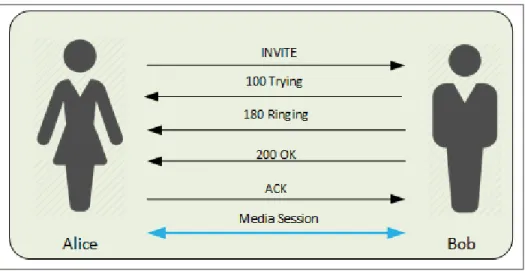
To understand the elements involved in a SIP exchange it is useful to illustrate the concept with a classical communication example: Alice and Bob. Alice wants to establish a voice communication with Bob whose endpoints are in at least one foreign network. As explained above, SIP uses a three-way handshake protocol to complete the session establishment. When Alice wants to establish a session, she sends an INVITE with the desired characteristics of the session, including the media and media transmission properties. Bob’s endpoint immediately replies with a 100 Trying to let Alice know that it is an actual entity capable of SIP communi-cation. Bob’s endpoint also sends a 180 Ringing to indicate that there has been a contact and that action from Bob is expected to complete the establishment. Once Bob answers, a 200 OK message is sent to Alice to indicate the request has been accepted, to which she would reply with ACK. This ACK request does not require a response. Media transmission starts. The set of events is illustrated in Figure 2.4.
Figure 2.4 Three-way handshake.
Providing the communication establishment is successful, a simplified message exchange is illustrated in Figure 2.5.
A frequently used tool is the SIP trapezoid. It can be used to illustrate the message exchange between all SIP entities in the communication path. A basic example of a SIP trapezoid is
Figure 2.5 Basic SIP Message Exchange.
shown in Figure 2.6, where a successful basic session establishment and media exchange are represented.
Figure 2.6 Basic SIP Trapezoid.
Even though Figure 2.6 shows initial communication establishment being routed through the proxies whilst subsequent SIP messages and media are exchanged directly, it could also happen that all communications flow exclusively through the proxies.
Understanding SIP trapezoids allows for easier understanding of SIP traces. In Figures 2.4 and 2.5 Alice and Bob are part of the same SIP domain and no proxies are required. On the other hand, Figure 2.6 includes the concept of proxies, which implies that Alice and Bob are on different SIP domains.
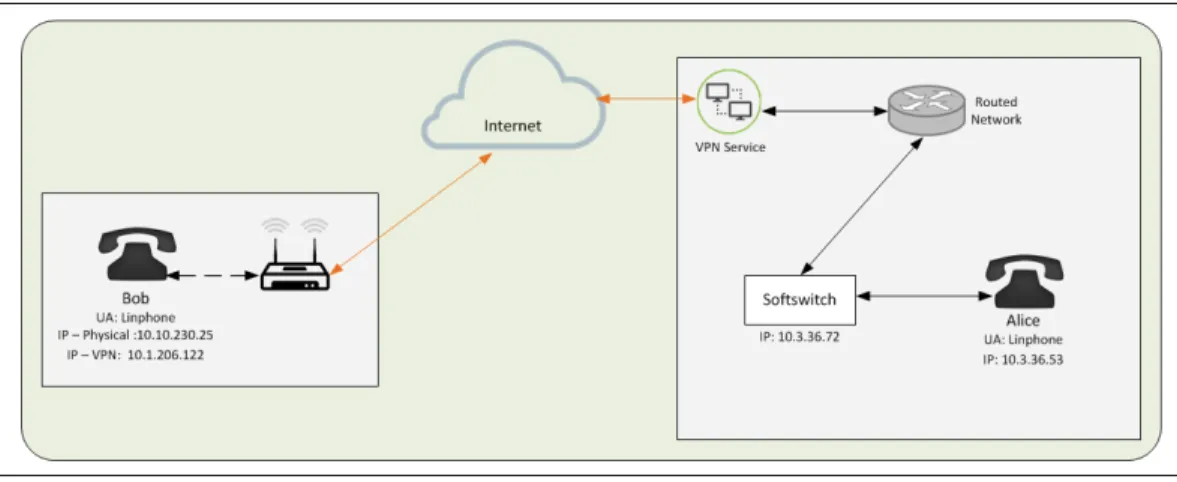
A testing scenario was configured to recreate and test SIP communication for this proposal. In the test environment Alice and Bob are in different locations as shown in Figure 2.7. Bob is at a remote location, connected through the Internet and establishing a VPN tunnel to the location where the softswitch is; Alice is collocated to the telephony switch. The tests on this proposal use FreeSwitch1as the softswitch, Linphone2as the endpoints and Cisco Any Connect3as the VPN client.
Figure 2.7 Physical Diagram (Bob and Alice).
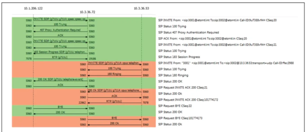
Figures 2.8 shows a SIP trace of the message exchange between Alice and Bob as seen from Bob’s side. To properly understand a SIP exchange, a dissection of the SIP messages follows.
1 freeswitch.org 2 www.linphone.org 3 goo.gl/rXRu9r
Figure 2.8 SIP Flowfor Alice and Bob (Bob Side).
The first SIP INVITE is sent by Bob’s UA. Since Bob does not know how to contact Alice, he sends the request to its own register server that takes the role of a SIP proxy for the communi-cation.
Figure 2.9 SIP INVITE (Bob to Proxy).
As shown in Figure 2.10, the SIP proxy lets Bob know that it is trying to complete the requested event.
Figure 2.10 SIP Trying (Proxy to Bob).
The SIP Proxy then realises that authentication is needed before serving any request from Bob. It sends an authentication request to Bob’s UA. The SIP proxy response includes a challenge along with basic information to build an appropriate SIP INVITE request as shown in Figure 2.11.
Figure 2.11 Authentication Request (Proxy to Bob).
Bob acknowledges the request.
Figure 2.12 Request Acknowledgement (Bob to Proxy).
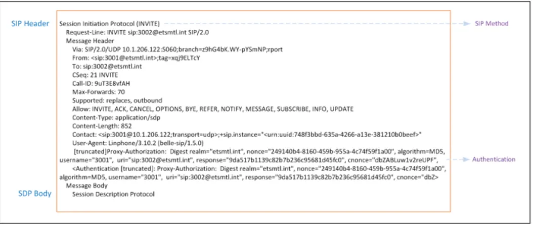
Bob sends a new SIP INVITE with the required authentication information. Figure 2.13 shows the new INVITE.
Figure 2.13 SIP Invite with Authentication (Bob to Proxy).
Once the use of the service has been granted, the proxy sends Bob a new indication that the process is going ahead.
Figure 2.14 SIP Trying response (Proxy to Bob).
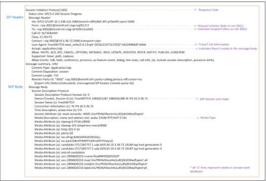
The proxy notifies Bob’s UA that a session is in progress. Since Alice’s UA has not been yet contacted, the telephony provider (which happens to be the same SIP proxy in this particular case) adds a SDP body indicating an upcoming artificial ring back tone or announcement. This is done in a 183 message as shown in Figure 2.15.
An INVITE, shown in Figure 2.16 is finally dispatched to Alice. Comparing against the ones in figures 2.9 and 2.13, some characteristics are worth highlighting:
• From and To headers are no different from the original INVITE.
Figure 2.15 183 Session in Progress (Proxy to Bob).
• Media attributes in the SDP are limited to PCMU, PCMA and Opus as supported by all
parties.
Alice’s UA dispatches response codes signalling that it is, first, trying to complete the request and then informing that the user is being notified. Figures 2.17 and 2.18 show the respective SIP Trying (100) and SIP Ringing (100) messages.
Figure 2.17 SIP Trying response (Alice to Proxy).
Figure 2.18 SIP Ringing (Alice to Proxy).
The proxy notifies Bob of the successful reception of the message. Figure 2.19 shows the corresponding 200 OK message.
Bob UA acknowledges the notification. Authentication information is included along with every SIP message from Bob as shown in Figure 2.20
Alice’s UA, notifies of the successful message delivery as illustrated in Figure 2.21.
The proxy then responds with an acknowledgement to Alice as shown in Figure 2.22.
At this point the communication path has been fully established and regular media (RTP in this example) flow starts or continues (early media could have been already sent) between the UA. In this particular testing layout the softswitch acts as the media gateway as well as the router (i.e. all media traffic necessarily traverses the softswitch).
Figure 2.19 SIP OK (Proxy to Bob).
Figure 2.20 ACK (Bob to Proxy).
There are many possible subsequent SIP messages: one of the parties may be put on hold, an additional media channel could be added, another party may join the call, etc. In the sample interaction Bob simply decides to terminate the call. Bob’s UA notifies the proxy that replies with a 200 OK and, in turn, notifies Alice, who also replies with a 200 OK. A summary of these four messages is shown in Figure 2.23. This concludes the message analysis exercise.
SIP as a signalling protocol which is proven to be clear and rigorous to establish trustworthy communication paths between parties. Although the process seems lengthy and cumbersome, in practice most of the heavy lifting is done by any chosen SIP framework. The base flow of
Figure 2.21 OK (Alice to Proxy).
Figure 2.22 ACK (Proxy to Alice).
the Alice and Bob message exchange is used to understand SIPBIO messaging flow later in this document.
Figure 2.23 SIP Dialog termination (Bob to Proxy, Proxy to Bob, Proxy to Alice, Alice to Proxy).
It is important to remember that SIP is a layered protocol that suits independent development of sections or functionalities. Notably, not every UA implements all layers. SIP layers can be summarized as follows:
Syntax and encoding. Defines how requests and responses are written.
Transport. Defines how UAs send and receive requests and responses.
Transaction. It can be thought as the set of client / server message exchanges needed to handle a specific request.
Transaction user. It is basically any SIP entity except for a stateless proxy (a message for-warder that does not actively participate in the communication).
So far, the concepts of SIP entities services have been presented without much explanation of their true nature. They are logical components, the former responds and acts to the logic of
requests while the later delivers extra enhanced functionality for the UA. SIP services are most
commonly implemented on a B2BUA due to their flexibility to modify signalling and routing as required.
This chapter has presented how a basic SIP implementation can manage the requirements of most multimedia sessions: establishment, maintenance, and finalisation. However, there are cases deemed very difficult to handle with the default SIP implementation. SIP can be adapted to such cases through extensions as defined in RFC 4485 (Rosenberg and Schulzrinne, 2006). The process of evaluating the need or suitability of a new SIP extension is discussed in the next chapter with some examples selected for their similarity (or complementarity) to SIPBIO.
2.3 SIP extensions
Previous sections displayed the power and flexibility of SIP to establish interactive communi-cations between endpoints across networks. SIP flexibility comes, in part, from the ability to extend core functionalities through extensions. These extensions are used to define new meth-ods, header fields, body types and parameters. Many have been proposed with some being widely used whilst others have never been adopted. This section introduces the guidelines to create SIP extensions and reviews some of those extensions from which SIPBIO borrows logic and functionalities.
2.3.1 SIP extensions guidelines
In RFC 4485, Rosenberg and Schulzrinne (2006) proposed a set of guidelines to author them. The aim of these guidelines is to be used as a reference for extension developers on SIP archi-tectural concepts. Clarity on the SIP architecture helps developers to evaluate the viability of a proposed extension. An overview of the proposed guidelines is shown next.
SIP Solution Space. SIP is a protocol for initiating, modifying, and terminating interactive sessions. This implies that SIP excels at finding remote parties to communicate with. SIP locates those remote parties through discovery. Subsequently, SIP can register sessions and fork communications. A key factor is the fact that SI is independent of the media session that it establishes.
SIP Architectural Model. Every proposed SIP extension must not violate any of the base protocol architectural concepts. Some of them are:
• Session Independence. The details of the media session are independent of the
ses-sion establishment: path independence.
• Multi-provider and multi-hop. SIP expects messages to traverse through different
networks.
• Proxies can ignore bodies. An extension cannot rely on a SIP Proxy analysing and
acting based on the body of a message. SIP Proxies are to ignore the body content.
• Proxies do not need to understand the method. No extension can rely on new methods
that need to be understood by proxies.
• An INVITE must be self-compliant. Any SIP message must be susceptible of being
processed. Behaviour based on collecting information across several INVITES and RE-INVITES must not be used.
• Generality is preferred over efficiency. It is preferable to offer capabilities covering a
large spectrum of cases rather than having specialized capabilities for a small subset of scenarios.
• The Request URI is the primary key for forwarding. All forwarding operations must
be guided by the Request URI which indicates the desired recipient of the message.
• Heterogeneity. No extension should have the constraint of only working if all devices
support it. The extension must handle the cases when there are non-compliant UAs.
• Other general requirements. Any proposed SIP extension must be backward
com-patible with base SIP implementations. Extensions should prefer default SIP security mechanisms. The definitions of each extension should comply with SIP terminology, syntactic, semantic and document formalities as stated in RFC 4485.
One of the restrictions previously presented (proxy agnostic or independence) comes as an advantage. Since proxies do not need to understand extensions behaviour, the design of the extension needs only to account for UA requests and responses. A de facto rule for any SIP implementation is that when sending requests, the protocol must be very strict, however, when receiving them the implementation must be flexible to deal with situations when there is in-compatibility. (Martinez, 2008b)
SIP can be extended in different ways: new headers, new methods, new content types. One of the most important things to consider during the design is how to handle the cases of