Sizing models and performance analysis of volumetric expansion machines for waste heat recovery through organic Rankine cycles on passenger cars
L. GUILLAUME A. LEGROS S. QUOILIN S. DECLAYE V. LEMORT
Thermodynamics laboratory of the University of Liège, Aerospace and Mechanical engineering department, BELGIUM
ABSTRACT
This paper aims at helping designers of waste heat recovery organic (or non-organic) Rankine cycles on internal combustion engines to best select the expander among the piston, scroll and screw machines, and the working fluids among R245fa, ethanol and water. The first part of the paper presents the technical constraints inherent to each machine through a state of the art of the three technologies. The second part of the paper deals with the modeling of such expanders. Finally, in the last part of the paper, performances of the various Rankine systems are compared and a decision array is built to select the most appropriate couple of fluid and expander.
0. NOTATIONS
Symbols
Greek letters
Subscripts
A
cf
f
h
N
P
s
t
T
U
v
V
w
Area
Dead volume factor
factor
Specific enthalpy
Mass flow rate
Rotational speed
Pressure
Heat flow rate
Volume ratio
Specific entropy
Temperature
Torque
Heat transfer coefficient
Specific volume
Volume
Displacement
Specific work
Power
[m²]
[-]
[-]
[J/kg]
[kg/s]
[RPM]
[Pa]
[W]
[-]
[J/kg.K]
[°C]
[N.m]
[W/m².K]
[m³/kg]
[m³]
[m³]
[J/kg]
[W]
ΔP
Proportional
losses
factor
Efficiency
Pressure difference
Density
[-]
[-]
[-]
[kg/m³]
0
a
adm
amb
c
calc
cp
ex
exp
in
leak
loss
meas
r
ref
sh
su
thr
Recirculated
Aspired
Admission
Ambiant
Compression
Calculated
Compressor
Exhaust
Expander
Internal
Leakage
Loss
Measured
Residual
Reference
Shaft
Supply
throttle
1. INTRODUCTIONThe interest in organic Rankine cycles for waste heat recovery on internal combustion engines has grown significantly for the past few years. Indeed, in such engines, only about one third of the energy available is actually converted into effective power, what remains being dissipated into heat. Therefore, since it becomes really challenging to increase the engine efficiency itself, solutions that focus on the recovery of this waste heat are increasingly investigated to improve the energetic efficiency of vehicles. Among these solutions, Organic Rankine Cycle systems are particularly appropriate.
The adoption of such technology in the automotive domain requires a specific R&D activity to select and develop the components and identify the most appropriate system architecture. Particularly, the selection of the
working fluid and of the expansion machine technology constitutes an important part of this research. Once identified the technical constraints inherent to each machine (rotational speed, pressure ratios, maximum temperatures, volumetric expansion ratios, etc.) and the performance reached in the scientific literature, a way to achieve the selection is to develop simulation models of the expanders. The performance of the Rankine system integrating these expander models could then be compared for various working fluids.
This paper attempts to address the problematic of selecting the expander and the working fluid for a waste heat recovery organic (or non-organic) Rankine cycles on a particular internal combustion engine. It focuses
especially on three technologies: the scroll, the piston and the screw expanders. Displacement expanders are generally preferred because of their lower rotational speeds compared to turbines and their ability to operate under large pressure ratios. Three working fluids: R245fa, ethanol and water are also investigated.
1 STATE OF THE ART
This state of the art aims at highlighting the limitations in terms of rotational speed, pressure and temperature. It is based on information available in open access scientific literature and data coming from manufacturers as well as on the experience gained at the Laboratory of Thermodynamics of Liège in the field of expansion machines.
More detailed information can be found in [1]. 1.1 Displacement and rotational speed
In theory, the displacement and rotational speed of piston expanders can reach values similar to those obtained for internal combustion engines. In Exoes [2], for example, the rotational speed of these machines usually varies between 500 and 6000 RPM. The upper limit of the speed may be due to mechanical constraints on the mechanisms of valve lifts. The importance of friction losses can also result in a limitation on the speed. The lower bound of the speed is relatively low, which can be explained by low internal leakage in this type of machine.
In practice, the range of scroll machine sizes is very broad and extends from mini-scroll of a few cubic centimeters to very large machine. Currently, the trend in the compressor industry is to increase their size. A the compressor Emerson ZP725K [3] is an example since its cooling capacity is about 158kW. According to the values observed in the literature, the displacement of the scroll expander generally varies from 1.1 to 49 l /s. Regarding the rotational speed, it often varies within a range of values between 1000 and 4000 RPM. However, speeds around 10,000 RPM are reached with scroll compressors in vehicle air-conditioning applications. Currently, screw expanders are often characterized by high capacities. Thus expanders whose capacity varies between 25 and 1100 l / s for produced powers of around 20kWe to 1 MWe can be found in the literature. There are very few studies on mini-screw expanders. Regarding the speed of these machines, it can reach relatively high values, up to 25,000 RPM.
1.2 Inlet temperature
Piston expanders can tolerate high inlet temperatures beyond 500 °C [4].
On scroll compressors, limitation relates to the discharge temperature. The maximum discharge temperature is usually between 154 and 160°C for hermetic compressor to avoid excessive thermal expansion of the machine and a potential degradation of the lubricant. In expander mode, an inlet temperature of 165 °C was achieved with air [5] and a temperature of 215 °C was reached with water vapor [6].
Screw expanders can be exposed to high inlet temperatures. For example, Hutker considered a value of 490 °C with water vapor [7].
1.3 Built-in volume ratio
The built-in volume ratio of the piston expander can also reach high values similar to those obtained with internal combustion engines. However, for a given displacement, an increase in the built-in volume ratio yields a decrease in specific work produced by the machine and a relative increase in friction losses. This is why, in practice, the value of built-in volume of piston machines usually varies between 6 and 14.
In refrigeration, the built-in volume ratio of scroll machines generally varies in a range between 1.5 and 3.5. Beyond a built-in volume ratio of 3.5, it becomes difficult to ensure adequate performance of the machine for a reasonable manufacturing cost. It is indeed difficult (and not economically viable) to maintain a good lateral seal between the spirals while increasing the number of pairs of contact points. However, in the literature, machines with built-in volume ratio greater than 4 exist (e.g., a scroll with a built-in volume ratio of 5.25 was proposed by Air Squared). They are often air compressors adapted to be tested as expanders.
In literature the built-in volume ratio of the screw machines is often limited to values of 4 or 5. Nevertheless, some studies show values of up to 8 [8].
1.4 Pressure ratio
The pressure ratio of the piston expanders could reach, by analogy to the displacement, similar values to those obtained by internal combustion engines.
The limitation on the pressure ratio of scroll machines is usually a consequence of the maximum allowable outlet or inlet temperature depending on whether the machine is operating in compressor or expander mode respectively. Thus, in refrigeration, the pressure ratio can reach a value of 11. In expander operation, a pressure ratio of 15 was achieved with water vapor [6]. The Eneftech company is working on the development of an expander capable of operating under a pressure ratio of 25 [5].
Screw expanders can be subjected to high pressure ratios. For example, Nikolov considers a value of 50 with ethanol [9].
2 EXPANDER MODELS
Semi-empirical simulation models of 3 different expansion machines were built into the Engineering Equation Solver (EES) software [10].
The proposed simulation models retain the most important physical phenomena inherent to the expansion machine and involve a limited number of parameters (~ 10) which are identified on the basis of performance points. Studies in laboratory showed that these models are able to predict the performance of the expansion machines with good accuracy. Moreover, their semi-empirical nature enables to extrapolate the performance of the machine for different operating conditions and design characteristics (displacement, sections of the inlet and exhaust ports, etc…).
2.1 Scroll and screw expanders model
The model used is the one proposed by Lemort and al. [11] which has been validated for the scroll expander (Figure 1). The different processes and losses occurring during the passage of fluid through the machine are described below.
Figure 1: Volumetric expander model
2.1.1 Description of the model
During the admission phase, the fluid undergoes a pressure drop as it enters through the inlet port. This pressure drop is modeled through an equivalent nozzle.
This supply pressure drop is followed by heat transfer losses when the fluid comes in contact with the wall of the expander. This heat exchange is assumed to occur between the fluid and fictitious isothermal wall.
After that, a part of the fluid flow rate is assumed to pass through the expansion machine directly from the inlet to the outlet without interacting with the mobile part and therefore without producing any mechanical power. The leakage path is modeled by means of a fictitious nozzle whose cross section is . The internal flow rate is thus defined as follow.
= −
The fluid is then subjected to expansion itself. The first part of this expansion is assumed to be an isentropic expansion from the inlet pressure to the pressure adapted to the built-in volume ratio of the machine. The second part of the expansion is assumed to be a constant machine volume expansion from the adapted pressure to the exhaust pressure (plus the pressure drop). This is actually a lamination of a part of the fluid caused by the contact of the old expansion chambers with the exhaust line.
The leakage flow is then mixed with the internal flow from the constant machine volume expansion. The enthalpy of the mixing is calculated using an energy balance, the process being assumed isobaric.
The fluid is finally discharged and it undergoes a pressure drop. The model used for the pressure drop at the outlet is similar to that used for the pressure drop at the inlet. A section of the throat of a fictitious nozzle , is identified using measurement points.
During the discharge phase are also expected losses by heat transfer between the fictitious isothermal wall and the working fluid. The model used is analogous to that used for the supply heat transfer losses. A nominal transfer coefficient , is identified by means of experimental data.
In the model developed by Lemort, the shaft power produced by the expander consists of three terms: • The internal power produced by the expansion: = ∗ ( !,"+ !,$)
• The constant mechanical losses: & ,'= 2 ∗ ) ∗ * ∗ +& • The losses proportional to the internal power: ∗
Both parameters +& (mechanical torque) and are determined experimentally, and N is the rotational speed of the expander.
Finally, the temperature of the fictitious isothermal wall is determined by means of a heat balance.
The coefficient of heat transfer between the wall and the atmosphere ,- is determined through experimental measurements.
In conclusion, there are finally 8 parameters to identify. 2.2 Piston expander model
A piston expander model is also proposed. It is based on the model developed in [12]. The same phenomena as those described above are expected to occur within this machine. The model is therefore composed of the same eight basic parameters.
However, in piston expanders, part of the flow going through the machine is re-compressed during the ascension of the piston in the cylinder. The description of this phenomenon increases the total number of parameters of the model.
As for the expansion, the recompression is assumed to occur in two stages, one isentropic compression until the adapted pressure followed by a constant machine volume compression.
A part of the available power is lost during the recompression and, similarly to the expansion, assumed to result from two contributions corresponding to the two compression types.
The internal flow rate is here defined taking into account the re-compressed mass flow rate as follow. = + '−
In the case of piston engines, durations for intake and discharge may be defined by means of two parameters, . and ./ respectively, expressed as function of the displacement of the engine and shown in the P-V diagram
below.
In this figure, 01 is a factor representative of the dead volume, .2, determines the volume of fluid in the cylinder at the moment when the intake valve closes. These parameters are linked by the following relations:
.2,= 01+ .
Figure 2: Theoretical P-V diagram of a piston expander
From these parameters can be defined the volume ratios of the machine in expander and compressor modes.
, , ! 1 .2, , ,/! 01 1 ./ 2.3 Models calibration
As mentioned above, the different parameters involved in the models are identified using measurements performed on real machines.
This identification is realized by minimizing the error between the predicted and measured values of the shaft power of the expander, of the outlet temperature of the expander and of the fluid mass flow rate.
In general, measurements are only available for a limited number of operating points. The model can therefore only be calibrated and validated in the range of the corresponding operating conditions. Outside this range, the bound on the error between the predicted and measured values is a priori unknown.
However, in this study, the assumption is made that the model can be extrapolated outside the range in which it has been validated, and the same set of parameters is used anyway. This approach is justified by the physical meaning of the parameters.
2.3.1 Screw expander
The screw expander model was calibrated on a machine running with Solkatherm. Figure 3 shows the predicted shaft power as a function of the power measured during tests on the real machine after calibration. The obtained parameters are as follow.
Table 1: Parameters of the screw expander model
, 4 [m²] 4 [W/K] [m²] , [m²] [W/K] [-] +& [Nm] ,-[W/K] 0.000128 10 0.000006151 0.001099 25 0.3 2.155 9.4
Figure 3: Calibration results of the screw expander model
2.3.2 Scroll expander
In this case, the measurements were performed in the laboratory of Liège with air and water for different operating conditions on an expander 38 cm³ and internal volume ratio of 4.1.
The various parameters of the model have been published [11].
2.3.3 Piston expander
The expander piston model has been calibrated on a machine using water. A set of parameters is available in the literature [12].
2.4 Scaling of the parameters
Since the first task is to size the expansion machines to compare the performance of different Rankine systems that would suit for the application, it is obviously not possible to use directly the previous models of expanders. One solution is to calibrate the models on the existing machines, as done in the previous section, and then use scaling relations for the parameters to adapt the models to the machines being currently sized.
Regarding the coefficients of convective heat transfer between the working fluid and the wall at the admission and discharge, they can be expected to vary as follows.
567
5689:,7= ;
< <89:=
'.?
(Assumption of turbulent flow)
Similarly, the throat sections of the fictitious nozzles can be assumed to vary with the square of the characteristic dimension of the expanders.
1, = @ , 1A
$ B
For the parameters related to mechanical losses, the proportional loss coefficient is retained while the mechanical loss torque is determined with the assumption that the ratio of the constant losses to the internal power is kept.
Finally, regarding the built-in volume ratio, the parameters of the existing machines were kept.
3 PERFORMANCE ANALYSIS
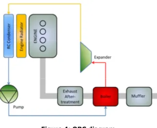
The expander models can then be integrated into complete cycle models. In fact, there are several possible architectures of Rankine systems depending on the heat sources available on the vehicle. In the frame of this paper, only the basic architecture, consisting in recovering the waste heat of the exhaust gases, is considered. Thus the Rankine system is constituted of a single evaporator, a condenser, a pump and an expander as depicted in figure 4.
Figure 4: ORC diagram
Thus, the performance of the systems can be evaluated and compared for the three expanders and the three working fluids. This comparison is achieved in the following sections for nominal conditions of a car engine and then for a less loaded point of the engine in order to compare the performance of the different system at part load.
3.1 Nominal operating conditions
The Rankine cycle and the expanders are sized on the nominal engine operating conditions (table 2). This sizing is obtained by mean of an optimization calculation whose goal is to get for each expander technology and each working fluid the Rankine system that produces the best performance in terms of shaft power. This optimization calculation is out of the scope of this study. Basically, the evaporating pressure of the cycle and the rotational speed of the expanders are optimized, taking into account the limitations presented in the state of the art, to maximize the shaft power of the expander. These two optimal values, combined with the assumptions made on the other parameters of the cycle (fixed superheating, subcooling and condensing pressure), enable to size the various components of the Rankine system.
Table 2 : operating conditions used for the design of the systems
Exhaust gases temperature [°C] 550
Exhaust gases mass flow rate [kg/s] 0.025
Superheating [°C] 5
Subcooling [°C] 5
3.1.1 Results
The simulation results for nominal operating conditions are presented below. In the two first columns of table 2, for each couple of expander and working fluid, the values of the two optimization variables (the supply pressure and the rotational speed of the expanders) are shown. As it can be seen, the supply pressure is generally higher in the case of R245fa. Indeed, in the case of this fluid, the condensing pressure (or exhaust pressure of the expander) is relatively high compared to the one of the other fluids. Consequently, the evaporating
pressure or supply pressure of the expander resulting from the optimization calculation is also higher in order to maintain a sufficient pressure ratio on the expander. Regarding the rotational speed, as it could be deduced from the state of the art, the piston expander rotates at a relatively low speed while the speed of the screw expander is much higher. The opposite behavior is observed for the displacements of the machine since, apart from the leakage flow rate, the flow rate, the displacement and the rotational speed of volumetric expanders can be linked by means of a linear relation. The last column of table 2 presents the obtained values of the isentropic efficiencies of the expanders.
Table 3 : Simulation results in nominal regime Exp. Type Fluid C4 [bar] N [RPM] C [bar] [cm³] [%] Piston R245fa 30 1600 3.43 12.9 60.57 Water 21 2350 1 12.83 58.50 Ethanol 18 1800 1 16.07 57.31 Scroll R245fa 21.3 3600 3.43 6.26 65.14 Water 15 7200 1 4.18 54.32 Ethanol 15 7500 1 3.69 54.24 Screw R245fa 30 13000 3.43 1.11 54.01 Water 30 25000 1 0.73 45.61 Ethanol 24 14500 1 1.2 48.1
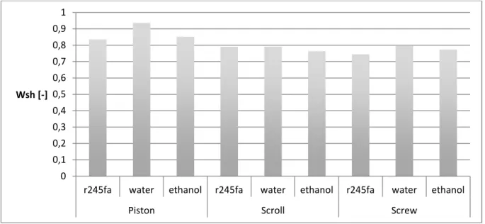
The performance obtained for the different couples of expander and working fluid can be compared in terms of shaft power. In figure 5, it is observed that even if the piston expander coupled to R245fa seems to be the most appropriate couple for the application, the results are too close to take a decision. Therefore, simulations were performed again but for a less loaded engine operating point.
Figure 5 : Predicted shaft power of the expanders in nominal regime
3.2 Part load conditions
A less loaded engine operating point yields a lower mass flow rate and a lower temperature of the exhaust gases of the engine. Simulations were performed under these conditions to compare the performance of the systems at part load. The simulation results are presented below.
0
0,1
0,2
0,3
0,4
0,5
0,6
0,7
0,8
0,9
1
r245fa
water
ethanol
r245fa
water
ethanol
r245fa
water
ethanol
Piston
Scroll
Screw
3.2.1 Results
As for nominal results, table 3 presents the obtained values of the two optimization variables and of the isentropic efficiencies of the expanders. These values are obviously reduced but the same tendency is observed
Table 4 : Simulation results in part load regime Exp. Type Fluid C4 [bar] N [RPM] C [bar] [%] Piston R245fa 17.2 525 3.43 22.93 Water 10 575 1 23.55 Ethanol 9.25 550 1 30.46 Scroll R245fa 12.8 1000 3.43 51.83 Water 6.2 1900 1 32.51 Ethanol 8 2000 1 38.49 Screw R245fa 23.5 2500 3.43 39.69 Water 11 7000 1 24.15 Ethanol 10.75 4700 1 35.74
Regarding the shaft power, results are compared in figure 6. As opposed to nominal results, best values are now obtained for the scroll and the screw expander when R245fa is used as working fluid. Therefore, part load results do not really help to achieve the selection and a new way has to be investigated.
Figure 6 : Predicted shaft power of the expanders in part load regime
4 QUALITY OF THE ASSUMPTIONS AND IMPROVEMENTS
Several assumptions were made to build the models of the three expander technologies and particularly for scaling the machines in order to adapt them to the considered waste heat recovery application. The strongest assumption is the variation of the throat sections of the fictitious nozzles with the square of the characteristic dimension of the expanders. Indeed, even if this assumption can be accepted for small variations of the size of the machines, it is not the case for larger variations.
The leakage area, which is one of the parameters that contributes the most to the losses, is submitted to this assumption. Therefore, this parameter can be misevaluated when the scaled machine is much larger than the initial one on which the parameters of the model had been calibrated. As a result, losses occurring in the machine can also be misevaluated and so can be the performance.
Therefore, further investigation should be achieved in order to identify how exactly varied this parameter with the size of the machine and thus predict more accurately the performance of the machine.
0
0,02
0,04
0,06
0,08
0,1
0,12
R245fa
Water
Ethanol
R245fa
Water
Ethanol
R245fa
Water
Ethanol
Piston
Scroll
Screw
5 DECISION ARRAY
A way to make the selection feasible is to compare the machines and the fluids on the basic of more qualitative criteria such as the freezing point of the fluid or the compactness of the machine. In the following array, several criteria are investigated. A weight from 1 to 5 is attributed to each criterion and a rating from 1 to 5 is
attributed to each couple of machine and working fluid for each of these criteria. The weighted sum taking into account all the criteria should then enable to select a fluid and a machine. Obviously, the list of criteria is non-exhaustive and the rating attributed for each criterion to each couple remains subjective. But, when achieved in a proper way by a sufficient number of experts, this solution should give good results.
In the array, it can be seen that the couple formed by the scroll expander and water, according to the selected criteria and the ratings and weights attributed, is the most appropriate solution.
Nonetheless, when criteria on the fluid are irrelevant, they can be set aside and the couple constituted of the scroll expander and R245fa is then the most appropriate.
Figure 7 : Decision array
6 CONCLUSION
Nine simulation models of Rankine systems were built for two operating points of the engine. The goal was to compare the performance of each system taking into account the limitations on the expander technologies. Unfortunately, the results did not enable to take a decision on the technology and the fluid to select. A decision array was then built to take criteria other than performance into account. According to the selected criteria and the ratings and weights attributed, the couple formed by the scroll expander and water appeared to be the most appropriate solution for the studied application.
7 REFERENCES
[1] Lemort V., Guillaume L., Legros A., Declaye S., Quoilin S.,A comparison of piston, screw and scroll expanders for small-scale rankine cycle systems, 2013.
[2] http://www.exoes.com
[3] R410A Copeland Scroll for Systems Up to 1 MW, http://www.emersonclimate.com/europe/en-eu/About_Us/News/Press_Releases (March 27, 2012)
[4] S.E. Eckard, R.D Brooks, Design of reciprocating single cylinder expanders for steam, Final report, Prepared for U.S. Environmental Protection Agency, Office of Air Pollution Control, Alternative Automotive Power Systems Division, Ann Arbor, Michigan (1973).
[5] Kane, M., D. Cretegny, D. Favrat, J. Maquet, Projet HTScroll, Nouveau système de cogénération à turbine spirale haute température, Rapport final, Département fédéral de l’environnement, des transports, de l’énergie et de la communication DETEC, Office fédéral de l’énergie OFEN, 29 octobre 2009.
[6] Lemort V., I.V. Teodorese, and J. Lebrun, Experimental Study of the Integration of a Scroll Expander into a Heat Recovery Rankine Cycle. 2006. 18th International Compressor Engineering Conference, Purdue, USA. [7] Hütker, J., and A. Brümmer. 2012. Thermodynamic Design of Screw Motors for Constant Waste Heat Flow at Medium Temperature Level. In: Proc. Of the In the InternaWonal Compressor Engineering Conference at Purdue. July 16--‐19 2012. Paper 1478.
[8] Brummer, Energy efficiency – waste heat utilization with screw expanders, Pumps, Compressors and Process Components, 2012.
[9] Nikolov A., Huck C., Brïmmer A., Influence of Thermal Deformation on the Characteristic Diagram of a Screw Expander in Automotive Application of Exhaust Heat Recovery, International Compressor Engineering Conference at Purdue, July 16-19, 2012.
[10] http://www.fchart.com/ees/
[11] Lemort V., Quoilin S., Cuevas C., Lebrun J., Testing and modeling a scroll expander integrated into an Organic Rankine Cycle, Applied Thermal Engineering 29, 3094-3102, 2009.
[12] Glavatskaya Y., Podevin P., Lemort V., Shonda O., Descombes G. 2012. Reciprocating Expander for an Exhaust Heat Recovery Rankine Cycle for a Passenger Car Application. Energies 5(6):1751-1765.