Science Arts & Métiers (SAM)
is an open access repository that collects the work of Arts et Métiers Institute of Technology researchers and makes it freely available over the web where possible.
This is an author-deposited version published in: https://sam.ensam.eu
Handle ID: .http://hdl.handle.net/10985/9877
To cite this version :
HenriFrançois BOYER, Nicolas RANC, M. FRABOLOT, Frank KOPPKA, Philippe LORONG -Simulating the Heat Distortiion of a Cast Iron Brake Disc during Dry Machining - In: 7eme Assises MUGV, France, 2012-10-16 - 7eme Assises MUGV - 2012
Any correspondence concerning this service should be sent to the repository Administrator : archiveouverte@ensam.eu
7ème Assises MUGV2012 ENISE – CETIM, Saint-Etienne, 16-18 octobre 2012
1
Simulating the Heat Distortiion of a Cast Iron Brake Disc
during Dry Machining
HF. Boyer
a,b*, N. Ranc
a, M. Frabolot
b, F. Koppka
b, P. Lorong
aa Arts et Métiers ParisTech, CNRS Laboratoire Procédés et Ingénierie et Mécanique et
Matériau, 151 boulevard de l’Hôpital, 75013 Paris, France – E-mail : henri-francois.boyer@renault.com.
b Renautl SA – Powertrain Process Engineering Division, FR CTR B02 1 30, 67 rue des
bons raisins, 92500 Rueil-Malmaison France.
Abstract: The application of MQL or dry machining in mass production becomes more
and more accepted. Dry (MQL) machining is a very efficient solution to reduce the usage of cutting fluids and represents an effective measure for an environmental friendly production. However, these techniques do not benefit any more from the stabilization in temperature obtained with cutting fluids. More important and more heterogeneous increases of the temperature are observed. This leads to distortions of the work piece during machining which are necessary to be taken into account to maintain the geometrical quality of the manufactured surfaces. In this paper, we present a strategy to handle these thermal induced distortions in an industrial context. This strategy couples finite element thermo-elastic simulations and temperature measurements of the work piece. In a first section, we describe a method to identify machined characteristics sensible to part temperature at loading. This method takes into account standard deviation of the process. A solution to adapt tool trajectories with a temperature measurement is proposed. Second part deals with distortions of the part during manufacturing. A method is proposed to simulate distortions along machining. These FEM simulations allow to identify impact of a machining on next operations. An application of the proposed approach for the machining of a cast iron brake disc is presented. Simulations are compared to measurements made in a dry manufacturing line.
7ème Assises MUGV2012 ENISE – CETIM, Saint-Etienne, 16-18 octobre 2012
2
1 Introduction
Manufacturers have to reduce their economical and environment impact in order to satisfy cost and legislative demands. One solution is to reduce use of cutting fluids during machining. Going from wet to dry or MQL machining (Weinert et al., 2004) is a big challenge in automotive industry. This article deals with some temperature issues encountered in a mass production line of cast iron (EN GJL 200) brake disc (Figure 3). In a first section, a short review of literature is done. This review describes some thermal aspects in machining (heat sources and distribution of heat between tool, work piece, chips and environment). Part 3 presents an industrial case of distortion during machining. In part 4, we describe a method to identify characteristic of parts sensible to workshop temperature variation and a solution to adapt automatically the production to part loading temperature. A Finite Element Method (FEM) to estimate distortions of work piece during manufacturing is presented in last section. This method allows prediction of zones affected by thermal distortions during manufacturing. It can help manufacturers to organize operations in line or to correct tool trajectories with heat input due to machining.
2 Thermal aspects in machining
Generally, authors consider that about 90 to 100% of energy associated with chip formation is converted to heat during machining. Figure 1 illustrates the five heat sources that could be observed: plastic strain in primary (T1), secondary (T3) and tertiary (T4) shear zone, friction between tool and chip (T3) and friction between tool and work piece (T5).
Figure 1 Heat sources during machining
Fleischer et al. (2007) made an extensive literary research to precise repartition of the cutting energy during machining (Table 1). According to the literature, the heat flow into the work piece fluctuates massively. For example, in turning, heat input into work piece is estimated at 1.1 – 20% of the cutting energy.
Table 1 Distribution of the cutting energy (Fleischer, 2007)
Drilling Turning Milling
Tool 5 – 15% 2.1 – 18% 5.3 – 10%
Work piece 10 – 35% 1.1 – 20% 1,3 – 25%
7ème Assises MUGV2012 ENISE – CETIM, Saint-Etienne, 16-18 octobre 2012
3
Many papers deal with tool or chip temperature prediction, there are only a few papers dealing with measurement of heat flow going into part. Authors developed two different approaches. On first hand, authors’ aim is to identify partition of cutting power going into part (Komanduri et al. 2001, Chou et al. 2005). On the other hand, authors directly identify heat input as a function of cutting speeds and tool geometry (Fleischer et al. 2007and Pabst et al. 2010 for milling operations, Zeilmann et al. 2006 and Battaglia et al. 2005 for drilling operations).
The literature research shows that the heat input into work piece is dependant of many factors: work piece material machinability, tool geometry and material, cutting conditions, wear, etc.
However precise estimation of the work piece heat input could not be known precisely, orders of magnitude allows to do FEM simulations and to analyse sensibility of parts to machining heat flows.
These temperature variations (due to part loading temperature and temperature rise during machining) affect process robustness, which lead to higher scrape rates. Process has to be watched carefully by operators to adjust machined dimension with parts measurements. These adjustments affect production level.
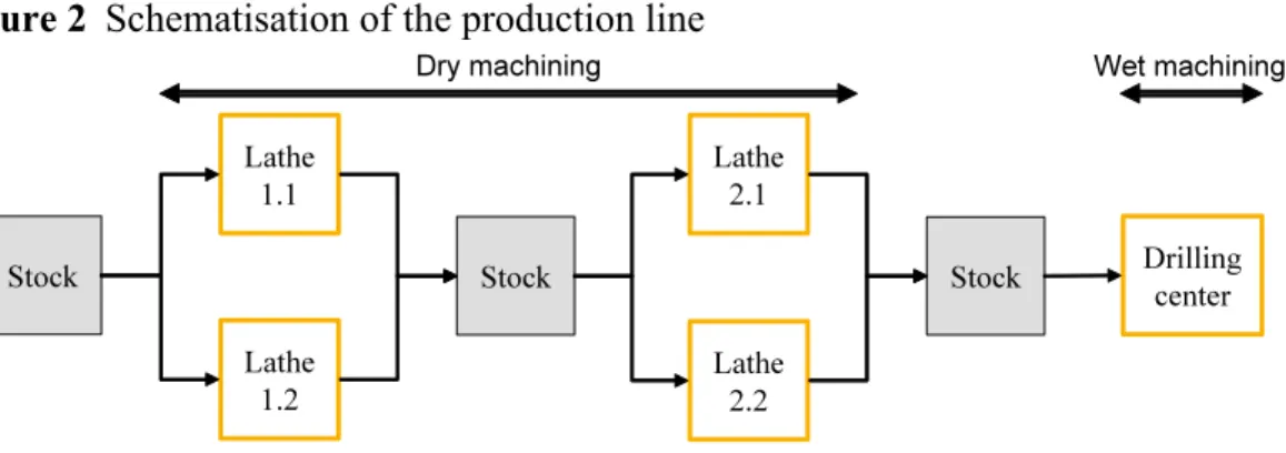
Figure 2 Schematisation of the production line
3 Problematic
Brake discs are machined in three steps: two dry turning operations and one wet drilling operation (Figure 2). Parts wait in a stock between each machine tool. For first and second operation, two lathes are disposed in parallel. Parts are machined randomly with one of the two lathes.
7ème Assises MUGV2012 ENISE – CETIM, Saint-Etienne, 16-18 octobre 2012
4
In this paper, a focus is made on cylinder 2 (Figure 3). This cylinder is machined during second dry drilling operation. Two quality issues are encountered for this machining: a variability of mean machined diameter and a form problem (variation of diameter between level 1 and level 3 < 5µm). Cylinder 2 mean diameter has to be machined between 61.811 and 61.841 mm to assure interference of a bearing.
Due to the lack of coolant, work piece temperature varies depending on different reasons: temperature of the workshop, heat flow due to previous machining and waiting time in stock. Figure 4 illustrates evolution of part temperature in the machining line. Temperatures were measured during one week in summer at loading and unloading
states. Workshop temperature varies from Tmin = 15°C to Tmax = 34°C. Temperature rise
is from ΔT1 = 8°C to ΔT1 = 10°C (mean 9°C) for first operation and from ΔT2 = 7°C to
ΔT2 = 13°C (mean 10°C) for second one.
Figure 4 Brake disc temperature variation along manufacturing line
4 Method to take into account initial temperature of the part
Machined geometry is linked to part loading temperature. To increase robustness, manufacturers have to stabilize part temperature at loading or to adapt production to initial part temperature.
At loading, temperature of the work piece depends on many factors; prediction of this temperature is not possible easily. If manufacturers know influence of a homogeneous temperature increase on part distortion, they can easily adapt their production to temperature. The following section, present a method to identify on a part which characteristics are sensible to thermal distortions.
5.1. Identification of characteristics sensible to thermal distortions
To identify which characteristic of part are sensible to thermal distortion, it is firstly necessary to estimate variability of the process (σ) without influence of temperature. Figure 5 shows for a one-dimension characteristic, influence of temperature on machined dimension.
7ème Assises MUGV2012 ENISE – CETIM, Saint-Etienne, 16-18 octobre 2012
5
To have 99.73% of parts in tolerance we have to be sure that equation:
(1) is right (for a centered process).
For a one-dimensional structure of length , thermal distortion introduces a new
dispersion of process that is independent of previous process dispersion. This new
deviation is represented on figure 5 for an intern characteristic and a positive variation
of temperature . Thermal distortion is given by the following equation:
(2)
with Δl distortion for length l, α coefficient of thermal expansion, ΔT difference between part temperature and reference temperature (generally 20°C).
Figure 5 Brake Example of result to estimate standard deviation of the process in one
dimension
Taking into account thermal deformation, equation (1) become:
(3)
Maximum temperature deviation allowed is given by:
(4) For instance, the diameter of cylinder 2 (figure 3), finished during second operation, has to be machined between 61.811 mm and 61.841mm. Standard deviation of the process with cooling is σ = 3 µm. Coefficient of thermal expansion is about α = 10.5µm/(m.K) for EN GJL 200 cast iron (Table 2). In order to produce in tolerance, part-loading temperature has not to vary more than 4°C between machine tool adjustment and start of machining for the part.
Table 2 Parameters for FEM simulations, cast iron EN GJL 200 Specific Heat Density Thermal
conductivity
Coefficient of thermal expansion
7ème Assises MUGV2012 ENISE – CETIM, Saint-Etienne, 16-18 octobre 2012
6
Equation (4) could be interpreted in a different way. When manufacturers use cutting fluids, they generally stabilize temperature of the liquid. This criteria illustrate maximum temperature variation allowed for the cutting fluid between two machine tool adjustments.
5.2. Correction of part loading temperature
Figure 6 illustrates correction implementation in machining program. Temperature measurement, made at loading is used to compute correctors. Then machining could begin. Some validations are done to avoid machining problems (comparison to last temperature measurement, control of temperature value …).
Figure 6 Correction implementation in machining program
Figure 10.A shows an example of tool trajectory compensation when part is warmer than reference.
5 Method to take into account initial temperature of the part
5.1. FEM Simulations
Thermo mechanical effect of the machining of a brake disc is simulated using a
commercial FEM to part represent 10% of power consumption for
cutting. Power consumptions were estimated using a linearized Kienzle model with = 1100 MPa.
(5)
with the cutting power, the cutting section and the cutting speed.
Table 3 and figure 3 shows plan of procedure for finish machining of brake disc (second dry operation).
Hypotheses for FEM simulations are:
• Material comportment is supposed linear and homogeneous
• Material volume removed by process is weak compare to part volume (<3%).
Simulations are done on finished part;
• Heat flow is not dependant of tool position on part. For one type of operation, heat
flow is constant (Battaglia et al. 2005);
• Heat flow is imposed in one step all over machined surface (short duration of
machining compare to duration of operation, Boyer et al. 2012);
• No heat exchange between part and jaw (small contact surfaces);
• Heat transfer coefficient (assumed constant):10 W/(m².K);
• Part is clamped with a three-jaw chuck (Fig. 1).
Part loading Temperature measurement Computation of correctors Machining Part unloading
7ème Assises MUGV2012 ENISE – CETIM, Saint-Etienne, 16-18 octobre 2012
7
Thermal and mechanical analyses are weakly coupled and are thus conducted successively. Table 3 compares thermal energy introduced in part to thermal losses by convection with environment. We remark that convection do not affect heat energy into part. For next analysis, if we just consider part during manufacturing heat convection could be neglected.
Table 3 Simplified plan of procedure for second operation Operation Heat flow Duration Thermal energy give to part Thermal energy variation into part Losses by convection with environment W s J J J
1 Finish turning face 2 2790 0,752 2098 2097 0,29
2 2,82 -1,17 1,17 3 Rough cylinder 2 2995 3,063 9173 9170 2,97 4 1,328 -1,68 1,68 5 Finish turning cylinder 1 500 0,224 112 111 0,28 6 3,044 -3,63 3,63
7 ½ finish turning cylinder 2 750 2,969 2226 2222 4,00
8 1,225 -1,74 1,74
9 Finish machining braking surfaces 1170(1) 7,256 8489 8474 14,95
10 4,903 -12,65 12,65
11 Finish turning cylinder 2 405 0,497 201 199 1,30
12 7,217 -18,90 18,90
13 Finish turning cylinder 3 400 3,601 1440 1430 9,88
TOTAL 38,899 23 741 23668 73,74
(1):585 W on each breaking surface
Figure 7 shows temperature of parts before finishing operation for cylinder 2. Heat flows and part geometry lead to an inhomogeneous repartition of temperature rise along
7ème Assises MUGV2012 ENISE – CETIM, Saint-Etienne, 16-18 octobre 2012
8
cylinder 2. On face 2 side, cylinder 2 is warm by face 2 finish machining; on face 1 side, there is thermal diffusion to rest of part.
Figure 7 Simulation of part temperature rise before finishing cylinder 2
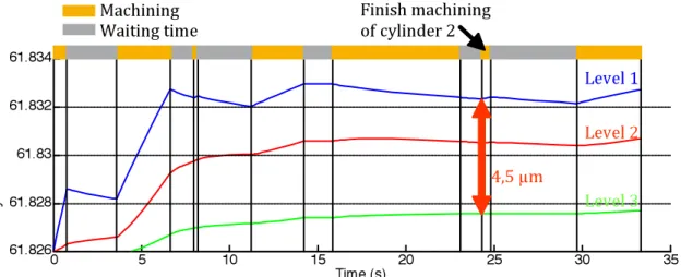
Simulated distortions during machining for cylinder 2 are represented on figure 8. Simulation shows a positive rapper of 4.5 between level 1 and 3 when finish machining of cylinder 2 starts. Temperature rise during manufacturing increases rapper of 4.5µm (hypothesis: 10% of power spindle is going to part). Machined parts measurement shows an average rapper increase of about 5 µm. To insure machined quality, it is necessary to cool parts or to take into account temperature rise of part during machining.
Figure 8 Variation of diameter for cylinder 2 at 3 levels (Fig. 3) during second
machining operation.
5.2. Correction implementation: temperature rise during machining
Temperature rises of parts depends on many factors: temperature of workshop, tool wear, cutting conditions, material machinability, etc and there effects on tolerance could be important.
7ème Assises MUGV2012 ENISE – CETIM, Saint-Etienne, 16-18 octobre 2012
9
A solution to take into account this warm up to correct tool trajectories is to measure temperature of parts at loading and unloading at the same point. This measuring point has to be representative of temperature in the affected by distortions zone.
Correction for a part is done with measurements done on previous part. To avoid errors due to bad measurements or quick changes in temperature rise (tool failure, replacement of tool, change in work piece material structure, stop of the production line …) measuring process has to be supervised. Figure 9 and 10.B illustrate this solution. Correction coefficient allows correction of machined cone. It is estimated with FEM simulations and has to be correlated to parts measurements.
Figure 9 Correction implementation of part temperature rise
6 Conclusion
In first part, a method was proposed to identify machined characteristic sensible to workshop temperature. This method allows manufacturers (if standard deviation of the process has been evaluated) to predict if machining operations needs thermo regulation of parts temperature or thermal correction of tool trajectories.
Figure 10 Tool trajectories with and without compensation
A. Compensation of part loading temperature
B. Compensation of part temperature increase during machining
FEM simulation method, presented in second part, could help manufacturers to understand thermo mechanical distortions of parts during manufacturing. This method could not predict exactly distortions of parts during manufacturing. It just allows rapid
Part loading
Temperature measurement
Machining
Correctors’ computation for next
part Part unloading
Temperature measurement Correctors compute
with previous part measurements
7ème Assises MUGV2012 ENISE – CETIM, Saint-Etienne, 16-18 octobre 2012
10
identification of order of magnitude for part temperature rise and distortions during machining. With this estimation, manufacturers could choose to do (or not) cooling of parts or thermal compensation during machining or could reorganize plan of procedure to minimize distortions.
Methods proposed were used to understand and solve thermo mechanical distortions problems in a cast iron brake disc dry machining line. Future work will focus on optimizing the accuracy of heat flow.
Acknowledgements
This paper presents work funded by the French agency for environment and energy consumption (ADEME) – Project Alusisec. Aim of this project is to study dry and MQL machining for automotive parts. The authors wish to thank Franck Jousse (Renault Le Mans) for his support.
References
Battaglia, J.L., Kusiak, A., 2005, Estimation of heat fluxes during high-speed drilling, International Journal of Advanced Manufacturing Technology, 26: 750 – 758 Boyer HF., Koppka F., Ranc N. and Lorong P. (2012) Identification of the heat input
during dry on MQL machining, 9th International Conference on High Speed
Machining
Chou, Y.K., Song, H., 2005, Thermal modeling for white layer predictions in finish hard turning, International Journal of Machine Tools and Manufacture, 45(4-5), 481 – 495
Fleischer, J., Pabst, R., Kelemen, S., 2007, Heat flow simulation for dry machining of power train castings, CIRP Annals - Manufacturing Technology, 56(1), 117 – 122 Komanduri, R., Hou, Z. B., 2001, Thermal modeling of the metal cutting process: Part I
Temperature rise distribution due to shear plane heat source. International Journal of Mechanical Sciences, 42(9) :1715 – 1752
Pabst, R., Fleischer, J., Michna, J., 2010, Modelling of the heat input for face milling process, CIRP Annals – Manufacturing Technology, 59, 121 – 124
Weinert, K., Inasaki, I. , Sutherland, J.W., Wakabayashi., T., 2004, Dry machining and minimum quantity lubrication, CIRP Annals - Manufacturing Technology, 53(2), 511 – 537
Zeilmann, R.P., Weingaertner,W.L., 2006, Analysis of temperature during drilling of Ti6Al4V with minimal quantity of lubricant, Journal of Materials Processing Technology, 179, 124 – 127