Science Arts & Métiers (SAM)
is an open access repository that collects the work of Arts et Métiers Institute of Technology researchers and makes it freely available over the web where possible.
This is an author-deposited version published in: https://sam.ensam.eu Handle ID: .http://hdl.handle.net/10985/9216
To cite this version :
Philippe MANGIN, Laurent LANGLOIS, Régis BIGOT - Contact Pressure Measurement System in Cross Wedge Rolling - In: Advances in Materials and Processing Technologies, France, 2010-10-24 - AIP Conference Proceedings AMPT 2010 - 2010
Any correspondence concerning this service should be sent to the repository Administrator : [email protected]
Contact Pressure Measurement System in
Cross Wedge Rolling
Philippe MANGIN, Laurent LANGLOIS, Régis BIGOT
Laboratoire Conception Fabrication Commande (LCFC), EA 4495 Arts et Métiers ParisTech, 4 Rue Augustin Fresnel, 57078 METZ Cedex 3 - FranceAbstract. In the cross wedge rolling process (CWR), plastic deformation is geared by a driving
torque transmitted by friction on die surface. Friction plays a role which has to be further identified in this metal forming process. The local contact pressure between a cylindrical billet and flat dies seems to be a relevant parameter to characterize the severe contact conditions during the rolling. This paper deals with an experimental measurement technology, which has been designed and implemented on a semi-industrial CWR test bench with plate configuration. This measurement system using pin and piezoelectric sensor is presented, with an analysis of the system operation and design detail. Characterization of systematic error and calibration tests are then explained. Additional tests performed on hot steel preforms allow to check the ability of the contact pressure measurement system to resist under severe operating conditions. Realistic results for varying temperatures are then discussed.
Keywords: Cross Wedge Rolling, Contact Pressure, Piezoelectric sensor, incremental metal
forming process.
PACS: 81.20.Hy, 81.70.Bt, 83.50.Uv, 85.50-n
INTRODUCTION
Cross wedge rolling is an incremental forming technology which allows producing metallic parts with revolution symmetry. The principle of this process consists in deforming a cylindrical billet with dies on the surface of which forming wedges are presents. The billet is deformed by the wedges which are progressively penetrating into the material and forcing it to flow. The figure 1 issued from HOLUB 1972 [1], represents the most common used configurations which are either plates with parallel motion (1.a) or rollers with parallel axis (1.b).
(a) Plates (b) Rollers
FIGURE 1. from HOLUB 1972 [1]: Most common configurations used in cross wedge rolling
Industrial applications for steel parts are achieved at hot temperatures either for preforming operations or for semi-finished parts. Among different condition, a
necessary requirement to operate a progressive plastic deformation is the permanent rolling of the workpiece. The rolling is geared by adhesion on die surface which allow to impulse a driving torque to the part. As soon as adhesion condition is interrupted at part / dies interface in the direction perpendicular to the billet axis, slipping is occurring as per description made by PIEDRAHITA et Al. [2]. Then there is an important risk of major surface defects creation and improper forming as it is outlined by LI and LOVELL 2002, [3]. For that reason, it is necessary to control the area where the friction has to be located during experiments on test bench as well during mass industrial production. Investigations to further understand the friction conditions between the deformable workpiece material and the hard die material require collecting information regarding the contact pressure. The aim of the present experiment is to determine the mean contact pressure at the interface. In fact, measuring the order of magnitude of the contact pressure has many benefits like giving an assessment of the tangential load at the surface with reference to the friction factor or delivering a reference value to be correlated with numerical simulation.
Toward that end, many systems have been developed in the past to measure contact pressure in rolling processes or in bulk metal forming. The pin and sensor technique is nowadays widely used in metal forming laboratory or in industry. These systems are implemented for normal load as well as for tangential load measurement, delivering valuable signal to determine contact pressure or coefficient of friction as depicted in LUPOI et Al. [4].
FIGURE 2. Sensitive pin construction as per LUPOI and OSMAN, [LO05]
In 1973, AL-SALEHI and Al. have employed a transmitting pin in cold rolling application [5]. In the paper, these authors highlight foremost, the importance to have a pin as small as possible to approximate the ideal point. Then it is indicated that a high-precision fit between pin and housing has to be realized to minimize friction and to avoid back extrusion. Finally, another design condition is reminded so as to avoid important local radial stiffness variations which would lead to disruption of the measured value. More recently, PLANCAK and Al. applied this technique with a focus of the initial pin position to reach the most realistic results of contact stress [6]. An optimal position of the pin is determined taking into account the elastic deformation and surrounding die surface. LUPOI and Al. presents in 2005, a general analysis of pressure sensing technique. In this paper, the complexity of this kind of measure is pointed out, especially due to heat, scale and material shearing actions. These severe conditions compel to insulate the sensor as much as possible by choosing a relative long distance from the die surface, or by using insulating zirconia layer for example [3]. Additionally the pin must be free to move so as to accommodate any elastic strain in its axial direction. Concerning the pin head position, these authors recommend to bring special attention to the pin/surface distance to avoid either delay in signal (pin below interface) nor initial artificial jump in pressure (initial impact with deforming material). According to PLANCAK et Al. [6] so as to LUPOI et Al. [4]
papers, the initial pin position has to be slightly above the surface of a distance of 1 to 2 tenths of a millimeter. To our knowledge, literature does not present any application of this sensing technique in cross wedge rolling. This paper investigates the design of a pin and piezoelectric load cell and the experimental validation of the set-up on a cross wedge rolling bench.
MATERIAL AND METHODS
Test Bench
One configuration in cross wedge rolling consists in reducing the section of a cylindrical billet with a die on which a single wedge has been machined (Fig. 3(a)). This elementary configuration has been adopted for experimental tests. To ensure the stability and regularity in displacement of the plates, a test bench has been designed as per figure 3(b), with reliable positioning and guiding solutions. The bench is composed of a sliding block (upper part) which is travelling vertically from the top to bottom and reverse. The guiding of the upper block is ensured by a frame which is fixed on the table of a 600kN hydraulic press. The stroke of the sliding block is 460 mm. The displacement can be measured and controlled by the hydraulic press.
Both plates facing each other are oriented with wedges in opposite direction. One die is fix and the second die is moving along a parallel plane, during the rolling operation.
(a) (b)
FIGURE 3. (a) Isometric view of the die, (b) Overview of the test bench
Wedge Geometry and Billet Description
The geometry of the die and wedges are defined as per data available in Table 1.
TABLE 1. Principal geometrical parameters of the CWR die
Parameter Value Unit
Spreading angle (β) 9 °
Forming angle (α) 30 °
Initial diameter of the billet (d0) 22 mm
Final diameter of the billet (d) 9,5 mm
Specific reduction εd = (d0 – d) / d0 0,57 -
Die length 220 mm
Pin and Piezoelectric Sensor
The technique of pin and load cell is implemented on one die having an inclined housing manufactured as per Figure 4. Pin is mounted into housing which axis is oriented so as to be coaxial with the local normal vector of the wedge surface.
Pin Sensor Cover Die
FIGURE 4. Cross sectional view of the pin sensor assembly (or measurement device)
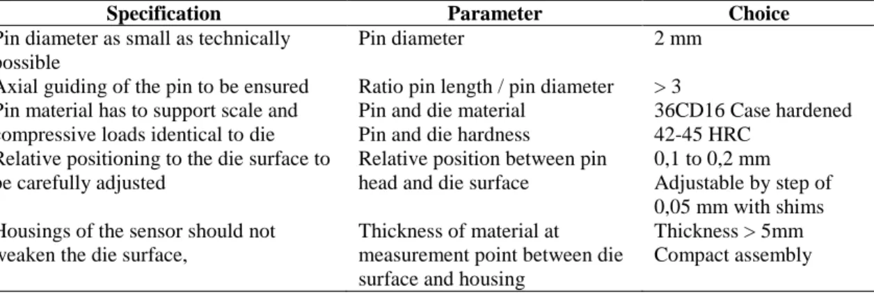
Under the pin, a commercial piezoelectric sensor is mounted and supported by a grooved cover. The running fits are manufactured as per ISO 286 H7g6 standard for accurate guiding of the pin. These very small clearances prevent the scale particles to enter the gap between pin and housing. Furthermore to reduce friction loss during compression of the pin body at housing surface, grease is applied to lubricate the contact. Given the fact that pin will be compressed by the load acting on his head, the relative distance of the pin-head to surface will vary. To verify the condition of non permanent deformation of the pin body after loading, maximum load is considered to be 1200 N. This value is assessed as per results of PATER 1996 [7], for steel C45 at 1000°C. The stiffness of the pin is then calculated with classical equation of strength of material. In association with the sensor stiffness given by constructor, the equivalent stiffness of the complete measuring system is found to be 57 N/µm. The pin length is also determined to be long enough to avoid important heat conduction to the sensor. The contact duration of the billet on the pin head is about 0,13 sec, depending on machine speed variation. During this transient period thermal expansion is neglected, in comparison to the elastic compression of the pin. Referring to literature specifications, the design of pin and sensor system has been conducted with characteristics chosen as per Table 2.
TABLE 2. Design parameters of the pin sensor system
Specification Parameter Choice
Pin diameter as small as technically possible
Pin diameter 2 mm
Axial guiding of the pin to be ensured Ratio pin length / pin diameter > 3 Pin material has to support scale and
compressive loads identical to die
Pin and die material Pin and die hardness
36CD16 Case hardened 42-45 HRC
Relative positioning to the die surface to be carefully adjusted
Relative position between pin head and die surface
0,1 to 0,2 mm Adjustable by step of 0,05 mm with shims Housings of the sensor should not
weaken the die surface,
Thickness of material at measurement point between die surface and housing
Thickness > 5mm Compact assembly
Calibration Test
The measurement device has been tested to determine intrinsic uncertainty. This uncertainty is resulting from manufacturing tolerances, positioning defects, elastic deformation of pin, or pin friction along the housing and can globally be considered as the systematic error of the measurement device. Furthermore the cross wedge rolling itself induces uncertainties like temperature variation of the billet, presence of scale on the workpiece surface, possible sliding or positioning variation during rolling. These entire phenomenon induce unknown margin of error. The role of calibration is to assess the margin of error under static compressive loading for the given measurement position. These tests have been performed for the sensor in axial direction and in another direction inclined at an angle of 30°. The angular tilt of the loading pin is used to characterize the systematic error due to friction increase because of inclined loading on the measurement pin head. Loading and unloading cycle from 0 to 1500N have been operated on 30kN press. Maximum systematic error due the mechanical assembly and friction interference has been found to be ± 7% at 30°.
Hot Steel Preforms Manufacturing
Further to the qualification, cylindrical billet made of steel C17 are used with initial diameter machined at 22mm and length at 50mm to manufacture workpieces with central diameter reduction to 9,5mm. The billets are heated in an oven under Argon atmosphere. Four samples are rolled for each temperature step, which are respectively 900 ° C, 1000°C and 1050°C. The measurement point is located in the middle of the inclined part of the wedge, for the stroke corresponding to 56mm. The distance between both dies is controlled to 22,3 mm ± 0,05.
RESULTS
The experiences with hot steel billets have delivered relative constant values of load, sample after sample. In Figure 5 are displayed the maximum load value extracted from the load signal measured for each workpiece.
900 1000 1100 1200 1300 1400 1500 1600 1700 1800 900 950 1000 1050 1100
Billet Initial Temperature [°C]
L o a d [ N ]
Load is found to be nearly between 1000 and 1700N depending of billet initial temperature. This corresponds to mean contact pressures between 296 and 505 MPa.
DISCUSSION AND CONCLUSION
Taking into account that load measurements are nearly constant from an acquisition to another, the reproducibility of the measure is validated. The order of magnitude of the loads matches well with literature reference [7]. The maximum load necessary to deform the material billet is even higher than the temperature is low. This is in good agreement with the decrease of flow stress occurring for growing temperature, confirming that high temperature rolling is favorable to reduce the forming loads. Others experiments are planned in the future to compare several material behavior so as to validate and to refine this conclusion.
Furthermore the reference value which has been used for the design of the measurement system seems to be slightly underestimated. Although it has to be reminded that relative distance of pin-head to surface on one hand and distance between dies surfaces on the other hand seems to play major roles in the magnitude of the measurement signal. For those reasons, further tests have to be carried out to point out clearly the influence of theses both parameters.
Improvements on the measurement system like applying special surface treatment of the pin could allow reducing the margin of error by reducing the friction at the contact area with housing.
ACKNOWLEDGMENT
This paper results from research project which is financially supported by CETIM Forge Committee and Région Lorraine. Special regards to Mr Pierre KRUMPIPE (CETIM) for his cooperative work.
REFERENCES
1. Holub, J., Cross Wedge Rolling. SNTL, Praha 1972
2. F. Piedrahita, L. Garcia Aranda and Y. CHASTEL. Three dimensional numerical simulation of
cross-wedge rolling of bars. Adv. Techn. of Plast. Proceedings of 8th ICTP – Verona, Italy (2005)
3. Q. Li and M. R. Lovell, "Predicting critical friction in a two-roll cross wedge rolling process," J.Tribol. 125 (1), 200-203 (2003).
4. R. Lupoi and F. H. Osman, "Under surface pressure sensing technique for the evaluation of contact stresses," Journal of Materials Processing Technology AMPT/AMME05 Part 2 164-165, 1537-1543 (2005).
5. F. A. R. Al-Salehi, T. C. Firbank and P. R. Lancaster, "An experimental determination of the roll pressure distributions in cold rolling," Int.J.Mech.Sci. 15 (9), 693-710 (1973).
6. M. Plancak, A. N. Bramley and F. H. Osman, "Some observations on contact stress measurement by pin load cell in bulk metal forming," Journal of Materials Processing Technology Proceedings of the 6th International Conference on Metal Forming 60 (1-4), 339-342 (1996).
7. Z. Pater, "Analysis of plane-strain rotational compression of rod by FEM," Journal of Materials Processing Technology Proceedings of the 6th International Conference on Metal Forming 60 (1-4), 549-554 (1996).
![FIGURE 1. from HOLUB 1972 [1]: Most common configurations used in cross wedge rolling](https://thumb-eu.123doks.com/thumbv2/123doknet/7279260.207262/2.892.256.658.915.1042/figure-holub-common-configurations-used-cross-wedge-rolling.webp)
![FIGURE 2. Sensitive pin construction as per LUPOI and OSMAN, [LO05]](https://thumb-eu.123doks.com/thumbv2/123doknet/7279260.207262/3.892.339.577.596.666/figure-sensitive-pin-construction-per-lupoi-and-osman.webp)