UNIVERSITÉ DE SHERBROOKE Faculté de génie
Département de génie civil
MÉTHODE DE CONCEPTION SIMPLIFIÉE DES
AMORTISSEURS POUR LA RÉHABILITATION
DES PONTS AVEC ISOLATION SISMIQUE DE LA
BASE
SIMPLIFIED DESIGN METHOD FOR ENERGY
DISSIPATING DEVICES IN RETROFITTING OF
SEISMICALLY ISOLATED BRIDGES
Thèse de Doctorat Spécialité : génie civil
PhD Thesis
Specialty: Civil engineering
Seyyed Behnam GOLZAN
Jury:
Rola ASSI
Sébastien LANGLOIS (Directeur) Frédéric LEGERON
Pierre ROCHETTE Nathalie ROY
i
ii
RÉSUMÉ
Les ponts routiers ont une grande valeur dans un pays parce qu’en cas de catastrophe naturelle, ils peuvent servir comme des lignes pour sauver des vies. Étant vulnérable sous des charges sismiques importantes, on peut considérer différentes méthodes pour concevoir des ponts routiers résistants et également pour réhabiliter des ponts existants. Dans cette étude, l'isolation de la base a été considérée comme une méthode efficace qui peut réduire significativement les effets des charges sismiques sur la structure. En réduisant la demande en ductilité sur la structure sans une augmentation notable de force, la structure est conçue pour rester élastique sous des charges sismiques. Le problème associé aux ponts isolés, particulièrement avec des appuis en élastomère, peut être leurs déplacements excessifs sous les charges de service et de séisme. Ceci peut défier l’objectif d'utiliser des appuis en élastomère pour les ponts typiques de petite portée où les joints de dilatation et les dégagements peuvent aboutir à une augmentation significative des frais d'exploitation et de maintenance. Ainsi, supplémenter la structure avec des amortisseurs d’une certaine rigidité peut servir de solution, ce qui peut cependant augmenter l’effort tranchant transmis à la sous-structure. Cette étude a pour but de fournir une méthode simplifiée afin d’évaluer les paramètres optimaux des amortisseurs dans les ponts isolés. Dans cette thèse, premièrement, basé sur une étude paramétrique, quelques directions sont données pour l'utilisation de dispositifs d'isolation simples, dont les appuis en élastomère, afin de réhabiliter des ponts existant avec une haute importance. Les paramètres comme la géométrie du pont, les clauses des normes et le type de sol sur lequel la structure est construite ont été appliqués sur un pont typique de deux portées. Il est conclu que les paramètres mentionnés peuvent déterminer l'emploi d'isolement de la base des ponts routiers. À la deuxième phase, basé sur le coefficient de réponse élastique des ponts isolés, une méthode de conception simplifiée d’amortisseur pour des ponts routiers réguliers isolés à la base a été présentée dans cette étude. En sélectionnant des objectifs pour la réduction du déplacement et la variation de l’effort tranchant, la rigidité et l'amortissement exigés d'un amortisseur hystérétique peuvent être déterminés. L’étude s’est poursuivie par une modélisation numérique d’un pont à deux portées pour vérifier l'efficacité de la méthode. Pour un modèle numérique d'un pont isolé typique, la méthode a été utilisée pour identifier des paramètres linéaires équivalents pour un certain déplacement et effort tranchant désigné. Par la suite, assumant un amortisseur de type hystérétique, les paramètres non linéaires de l’amortisseur ont été calculés et utilisés. La comparaison des résultats du modèle numérique sans amortisseur et avec l'amortisseur a démontré que la méthode proposée est suffisamment précise. Par la suite, un nouvel amortisseur hystérétique simple en acier a été conçu. Cinq spécimens ont été fabriqués de deux différents grades d’acier et ont été testés en combinaison avec un isolateur à l’échelle réelle dans le laboratoire de structures de l'Université de Sherbrooke. La procédure comprenait la caractérisation des spécimens par des tests cycliques en contrôle de déplacement et par la suite la réalisation d’essais par la méthode de sous-structuration dynamique en temps réel. Les résultats des essais ont été utilisés pour établir un modèle numérique du système qui a subi des analyses temporelles non linéaires sous plusieurs séismes. Le résultat des essais expérimentaux et numériques montrent une conformité acceptable avec la méthode simplifiée.
Mots clés: Ponts routiers, conception parasismique, isolation de la base, amortisseur, méthode de conception simplifiée, analyse dynamique linéaire et non linéaire, essai cyclique, essai de sous structuration dynamique en temps réel.
iii
ABSTRACT
Highway bridges have great values in a country because in case of any natural disaster they may serve as lines to save people’s lives. Being vulnerable under significant seismic loads, different methods can be considered to design resistant highway bridges and rehabilitate the existing ones. In this study, base isolation has been considered as one efficient method in this regard which in some cases reduces significantly the seismic load effects on the structure. By reducing the ductility demand on the structure without a notable increase of strength, the structure is designed to remain elastic under seismic loads. The problem associated with the isolated bridges, especially with elastomeric bearings, can be their excessive displacements under service and seismic loads. This can defy the purpose of using elastomeric bearings for small to medium span typical bridges where expansion joints and clearances may result in significant increase of initial and maintenance cost. Thus, supplementing the structure with dampers with some stiffness can serve as a solution that in turn, however, may increase the structure base shear. The main objective of this thesis is to provide a simplified method for the evaluation of optimal parameters for dampers in isolated bridges. Firstly, performing a parametric study, some directions are given for the use of simple isolation devices such as elastomeric bearings to rehabilitate existing bridges with high importance. Parameters like geometry of the bridge, code provisions and the type of soil on which the structure is constructed have been introduced to a typical two span bridge. It is concluded that the stiffness of the substructure, soil type and special provisions in the code can determine the employment of base isolation for retrofitting of bridges. Secondly, based on the elastic response coefficient of isolated bridges, a simplified design method of dampers for seismically isolated regular highway bridges has been presented in this study. By setting objectives for reduction of displacement and base shear variation, the required stiffness and damping of a hysteretic damper can be determined. By modeling a typical two span bridge, numerical analyses have followed to verify the effectiveness of the method. The method has been used to identify equivalent linear parameters and subsequently, nonlinear parameters of hysteretic damper for various designated scenarios of displacement and base shear requirements. Comparison of the results of the nonlinear numerical model without damper and with damper has shown that the method is sufficiently accurate. Finally, an innovative and simple hysteretic steel damper was designed. Five specimens were fabricated from two steel grades and were tested accompanying a real scale elastomeric isolator in the structural laboratory of the Université de Sherbrooke. The test procedure was to characterize the specimens by cyclic displacement controlled tests and subsequently to test them by real-time dynamic substructuring (RTDS) method. The test results were then used to establish a numerical model of the system, which went through nonlinear time history analyses under several earthquakes. The outcome of the experimental and numerical showed an acceptable conformity with the simplified method. Key words: Highway Bridge, seismic design, base isolation, damper, simplified design method, linear and nonlinear dynamic analysis, cyclic testing, real-time dynamic substructuring testing
iv
ACKNOWLEDGMENTS
Firstly, I would like to express my sincere gratitude to my advisors first Prof. Frédéric Legeron and later Prof. Sébastien Langlois for the continuous support of my PhD study and related research, for their patience, motivation, and immense knowledge. Their guidance helped me in all the time of research and writing of this thesis. Particularly, I appreciate the efforts that Prof. Langlois did in performing the experiments and reviewing all scientific papers and the chapters of this thesis.
This research is part of the Canadian Seismic Research Network. I gratefully acknowledge the financial support of the Natural Sciences and Engineering Research Council of Canada (NSERC) under the strategic Research Networks program.
Besides my advisors, I cordially appreciate the kind contributions of Dr. Ehsan Ahmed for enlightening me the first phase of research and for his great contributions in reviewing my publications. My sincere thanks also go to Mr. Marc Demers for his insightful comments and encouragement in realizing the experiments and consequently reviewing and editing the manuscript of my publications. Mr. Demers did a great job in preparing the test setup and performing all the tests with great patience and precision.
I also thank Dr. Gustavo Siqueira for his insightful comments in the beginning of the project, Mr. Alex Loignon for his great contributions in performing the RTDS tests and Mr. Frédéric Turcotte for his professional contributions in the preparation of the test setup and fabricating and installing the specimens.
I appreciate sincerely all my friends as well who were so helpful and understanding throughout my PhD study.
Last but not the least, my special warm thanks go to my family: My parents, Seyyed Masoum and Fatemeh and my sister, Seyyedeh Maedeh who patiently encouraged and supported me spiritually over the period of my PhD study and accepted my being away for a long period.
v
TABLE OF CONTENTS
RÉSUMÉ ... ii ABSTRACT ... iii ACKNOWLEDGMENTS ... iv LIST OF FIGURES ... ixLIST OF TABLES ... xii
LIST OF SYMBOLS ... xiv
LIST OF ACRONYMS ... xvi
CHAPTER 1. INTRODUCTION ... 1
1.1 Bridge retrofitting ... 1
1.2 Overview on base isolation ... 2
1.3 Energy dissipating devices ... 3
1.4 Structural analysis and codes ... 3
1.5 Research objective ... 4
1.6 Research significance and originality ... 4
CHAPTER 2. STATE OF THE ART ... 6
2.1 General Framing ... 6
2.2 Conventional bridges and issues with their analysis and design ... 7
2.3 Design and analysis requirements in codes ... 8
2.3.1 Seismic design principles in codes ... 8
2.3.2 Peak ground acceleration and uniform hazard spectrum ... 9
2.3.3 Seismic parameters ... 10
2.3.3.1 Eurocode 8 ... 10
2.3.3.2 CSA S6 (2006) and AASHTO (2007 and earlier) ... 11
2.3.3.3 AASHTO (2010 and 2012) ... 13
2.3.3.4 CSA S6 (2014) ... 14
2.4 Base isolation issues and available systems ... 15
2.4.1 Elastomeric bearings ... 15
2.4.2 Sliding (Frictional) isolation systems ... 17
2.5 Passive energy dissipating devices ... 20
2.5.1 Fluid viscous dampers (FVDs) ... 20
2.5.2 Solid viscoelastic dampers (VEDs) ... 21
2.5.3 Hysteretic metallic yielding dampers (MYD) ... 21
2.5.4 Hysteretic friction dampers ... 23
2.6 Constitutive laws for isolation and damping devices ... 23
2.6.1 Equivalent linearization method ... 26
2.7 Analysis and design methods of isolated bridges ... 27
2.7.1 Analysis methods ... 27
2.7.1.2 Single-mode spectral method ... 28
2.7.1.3 Multi-mode spectral method ... 28
2.7.1.4 Time-history method ... 32
2.7.2 Regularity of bridges and their analysis requirements ... 33
2.8 Demand-capacity design methods ... 34
2.9 Conclusion ... 35
CHAPTER 3. PROJECT METHODOLOGY ... 38
3.1 Parametric study of isolated bridges ... 39
3.2 Supplementing the isolated structures with dampers ... 40
3.2.1 Equivalent model ... 40
3.2.2 Concept of design ... 42
3.3 Three-dimensional finite element modelling ... 43
3.3.1 Linear analysis with equivalent values ... 44
3.3.2 Nonlinear analysis with nonlinear parameters ... 44
3.4 Design and testing a hysteretic damper ... 45
3.4.1 Displacement controlled cyclic and hybrid testing ... 45
3.4.2 Numerical modeling ... 47
CHAPTER 4. ISOLATED BRIDGE PARAMETRIC STUDY ... 49
4.1 Introduction ... 50
4.2 Parametric study: a comparison between traditional and isolation design ... 51
4.2.1. Presentation of the study case ... 52
4.2.2. Methodology of the study ... 52
4.2.3. Results of the parametric study ... 54
4.3 Analysis of the results of the parametric study and discussion ... 57
4.3.1. Influence of the importance factor ... 57
4.3.2. Influence of soil site ... 58
4.3.3. Influence of R-factor ... 58
4.3.4. Influence of stiffness of pier ... 58
4.3.5. Influence of weight of bridge ... 59
4.4 Additional considerations ... 60
4.4.1. Choice of isolation or non-isolation system when pier force is similar ... 60
4.4.2. Comments on use of CSA S6 (2006) for isolation bearing ... 61
4.4.3. Serviceability of bridge with isolation bearing ... 62
4.4.4. Post-earthquake serviceability ... 62
4.5 Conclusion ... 63
CHAPTER 5. SIMPLIFIED DAMPER DESIGN METHOD ... 65
5.1 Introduction ... 67
5.2 Concept development ... 68
5.2.1 Basic assumption and method ... 70
5.2.2 Obtaining Target Stiffness of Dampers ... 73
5.2.3 Obtaining equivalent damping ratio of dampers ... 74
5.3 Bridge model ... 76
5.4 Numerical modeling ... 78
5.4.2 Time history analysis ... 82
5.5 Concluding remarks ... 86
CHAPTER 6. EXPERIMENTAL HYSTERETIC DAMPER DESIGN ... 89
6.1 Introduction ... 91
6.2 Simplified design method ... 93
6.3 Experimental setup ... 95
6.4 Characterizing the isolation bearing ... 97
6.5 Designing a hysteretic damper ... 98
6.6 Testing isolation bearing and dampers ... 101
6.6.1. Displacement controlled cyclic tests ... 101
6.6.2. Real-time dynamic substructuring tests ... 103
6.7 Extending study with numerical modelling ... 108
6.8 Concluding remarks ... 111
CHAPTER 7. SUMMARY, CONCLUSIONS, AND FUTURE RESEARCH ... 114
7.1 Summary and conclusions ... 114
7.1.1. Recommendations on CSA-S6-06 ... 114
7.1.2. Simplified damper design method ... 115
7.2 Research limitations ... 116
7.3 Recommendation for future works ... 117
CHAPTER 8. SOMMAIRE, CONCLUSIONS ET TRAVAUX FUTURS ... 120
8.1 Sommaire et conclusions ... 120
8.1.1. Recommandations sur le code CSA S6-06 ... 120
8.1.2. Méthode simplifiée de la conception d’amortisseur ... 121
8.2 Limites de cette étude ... 123
8.3 Recommandations pour les travaux futurs ... 123
APPENDIX A― Procedure of the design of a steel damper ... 126
APPENDIX B― Practical damper installation ... 129
ix
LIST OF FIGURES
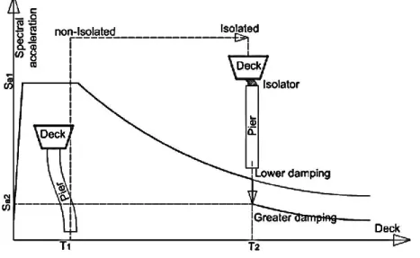
Figure 1.1.Design spectrum and the shift of spectral ordinates for an isolated structure ... 2
Figure 2.1. Eurocode spectra type one (a) and two (b) (Eurocode 8, 2005)... 11
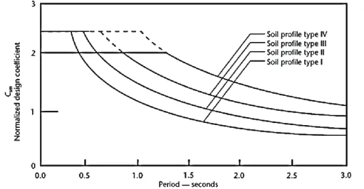
Figure 2.2. Elastic response coefficient for various soil types (CSA S6, 2006) ... 12
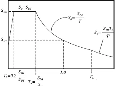
Figure 2.3. Definition of Csm in AASHTO (2010) ... 14
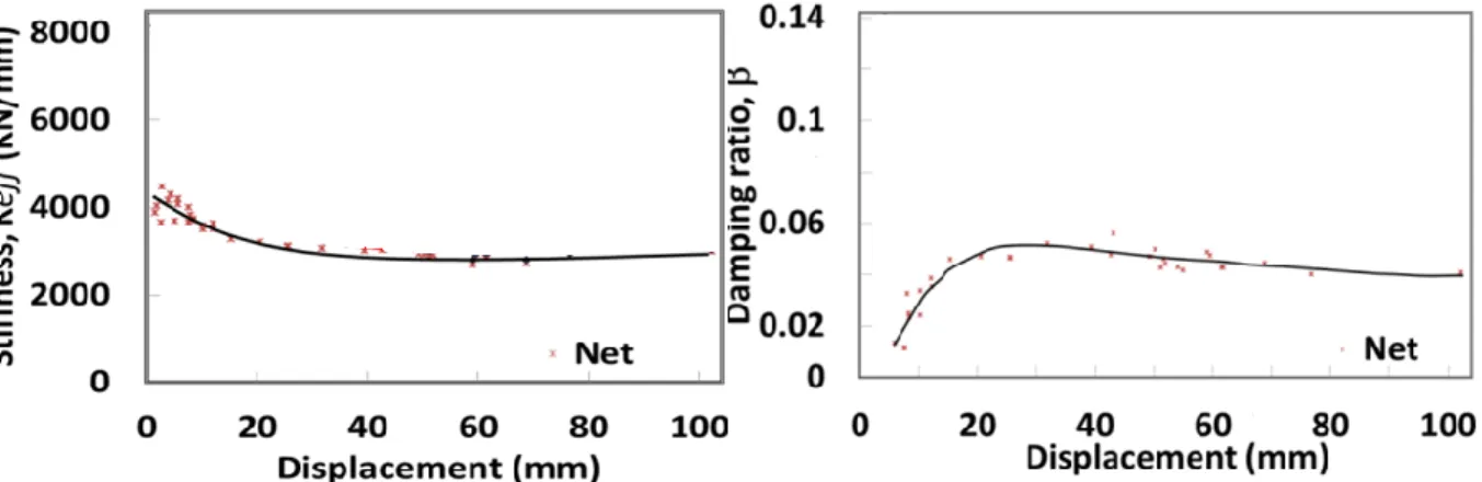
Figure 2.4. Behavior of an LRB bearing at different strain levels ... 16
Figure 2.5. Elastomeric isolation bearings ... 17
Figure 2.6. Sliding type isolation systems (Khodaverdian, 1987)... 18
Figure 2.7. Sliding type isolation systems (FPS System) ... 19
Figure 2.8. Steel bar damper installed with rubber isolation bearing (www.civildigital.com) . 23 Figure 2.9. Two-DOF bridge structure ... 29
Figure 2.10. Demand response spectra in ADRS format for different values of damping ... 35
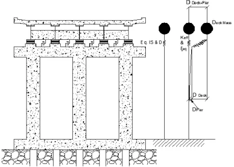
Figure 3.1. Effective stiffness and equivalent damping of the SDOF Structure ... 41
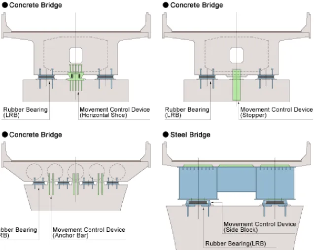
Figure 3.2. Different movement control devices for bridges (www.oiles.co.jp) ... 42
Figure 3.3. Assumption of damper stiffness and structural damping with/without damper ... 43
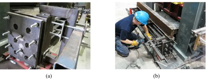
Figure 3.4. End fixation of the elements (a); Cutting out the elements to replace (b) ... 46
Figure 3.5. Hinged loading plate and sleeves (a); Damper under loading (b) ... 46
Figure 4.1. Comparison between the Csm and C’sm in soil type II ... 51
Figure 4.2.Typical bridge used in the parametric study ... 52
Figure 4.3.Variation of period of vibration with zonal acceleration ratio and site coefficient . 55 Figure 4.4. Results for L=35m, K = 100,000 kN/m, W= 100kN/m and R=3 ... 57
Figure 4.5. Results for L=35m, K = 100,000 kN/m, W= 100kN/m and R=5 ... 59
Figure 4.6. Results for L=35; K=25; W=100; R=3 ... 60
Figure 4.7. Results for L=35; K=250; W=100; R=3 ... 60
Figure 4.8. Results for L=50; K=100; W=100; R=3 ... 60
Figure 4.9. Results for L=35; K=100; W=50; R=3 ... 60
Figure 5.1. Effective stiffness and equivalent damping of a SDOF structure ... 69
Figure 5.2. Response with added stiffness and damping ... 70
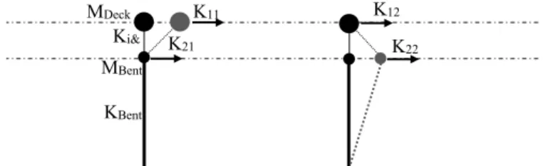
Figure 5.3. Typical two span isolated-damped bridge analysis model ... 77
Figure 5.4. Structure and damper correlation in terms of stiffness and damping ratio based on simplified method for five scenarios of ε and φ... 78
Figure 5.5. Design and mean spectra for the accelerograms ... 80
Figure 5.6. Bilinear model parameters ... 83
Figure 5.7. Bilinear model of one isolator (a); Ki (displ.) and ξi(displ.) of the total isolation system ... 83
Figure 5.8. Displacement and base shear history for Kc=147700 kN/m ... 85
Figure 6.1. Isolated and damped bridge ... 93
Figure 6.2. Test setup for isolation bearing and damper ... 95
Figure 6.3. Roller between vertical jacks and the sliding plate over the bearing (a & b); Isolation bearing (b) ... 96
Figure 6.4. Behavior of the bearing at different displacements... 97
Figure 6.5. Conceptual configuration of the damper (a); Energy dissipation on plastic cross section (b) ... 99
Figure 6.7. Comparison of the combined system vs. isolation only for two specimens ... 102 Figure 6.8. Effective stiffness and equivalent damping ratio of specimens in various
displacements ... 103 Figure 6.9. Configuration for RTDS testing on a SDOF model ... 105 Figure 6.10. Displacement and force history of HR1 and CR3 with and without isolator under Northridge 30% ... 106 Figure 6.11. Hysteretic response of HR1& CR3 with and without isolator under Northridge 30% ... 106 Figure 6.12. Numerical model (a); Test& analysis comparison under Northridge 30% ... 109 Figure 6.13. Numerical results for specimens under design accelerograms of scaled
xii
LIST OF TABLES
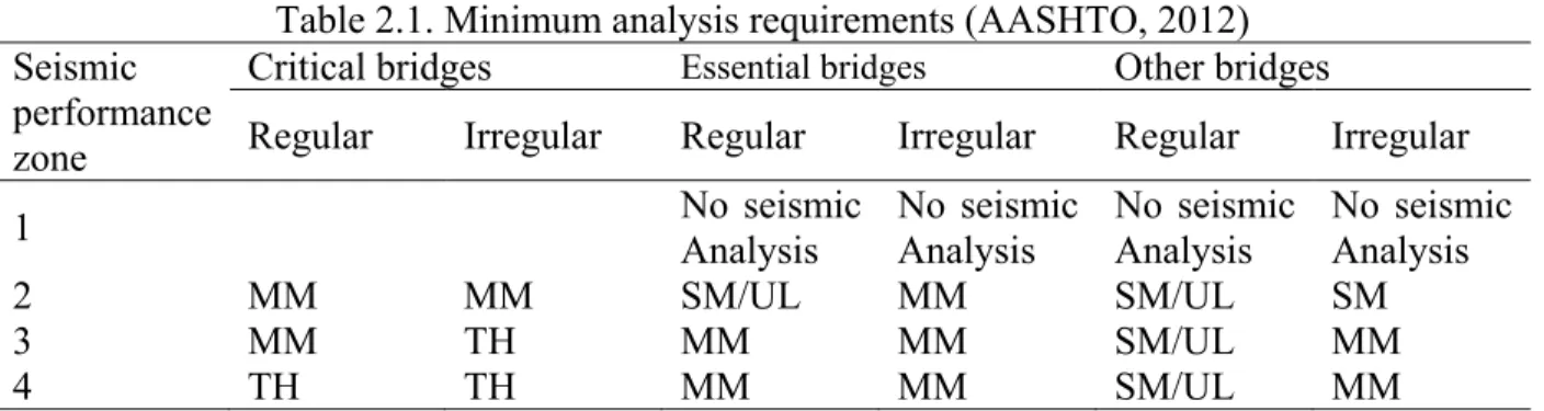
Table 2.1. Minimum analysis requirements (AASHTO, 2012) ... 34
Table 2.2. CSA S6-06 minimum analysis requirements ... 34
Table 4.1. Size of bearings for all cases ... 56
Table 4.2. Comparison of site coefficient for isolated and non-isolated bridge-Soil profile type ... 58
Table 5.1. Analysis input and results (kN; m) for response spectrum method ... 81
Table 5.2. Simplified method versus response spectrum analysis results ... 82
Table 5.3. Nonlinear properties of the isolation system ... 84
Table 5.4. Average nonlinear DINTH analysis results for Kcy =104300 (kN;m) ... 85
Table 5.5. Simplified method versus average DINTH analysis results ... 86
Table 6.1. Design properties ... 101
Table 6.2. RTDS testing results for specimens under Northridge scaled to 30% ... 107
xiv
LIST OF SYMBOLS
Symbol Definition
[.] First derivative relative to time [..] Second derivative relative to time
Strain hardening ratio (Ratio of Kpl to Kel)/ Hilber-Hughes-Taylor coefficient Shape parameter of the hysteretic loop
Sliding deformation
Rate of variation of base shear relative to the initial base shear Ductility ratio (Ratio of D to Dy)
f Constant coefficient of friction c Structural equivalent damping ratio d Damper viscous damping ratio
eq Equivalent damping ratio of the bridge i Isolator viscous damping ratio
2i+d Isolator and damper equivalent viscous damping ratio nm Modal correlation coefficient
Shape parameter of the hysteretic loop
φ Rate of variation of displacement relative to the initial displacement [φ] Matrix of the mode shapes/components of mode shape matrix mn Circular frequency of the system; for mth and nth mode of the system A Zonal acceleration ratio (m/s2)
As Shape parameter of the hysteretic loop a0 & a1 Rayleigh damping coefficients
ag Design ground acceleration on rock or similar ground type a/v Ratio of PGA to PGV
B Damping reduction factor (damping coefficient) C Linear viscous damping coefficient
[C] Damping matrix/components of damping matrix Ceq Equivalent damping of the bridge
Ci Damping coefficient of the isolation system Cd Damping coefficient of the damping system Csm Elastic seismic coefficient
C'sm Isolated elastic seismic coefficient
d Bar diameter
D Total Displacement
Dc Substructure displacement
Di+d Displacement across isolator and damper together Dy Yield displacement
E Modulus of elasticity
exp Elastoplastic hysteresis retrieval
[F] Seismic load matrix/ components of seismic load matrix F Friction force
FR Recentering force F(t) Restoring force
f(t) Ground excitation force
Fv Site factor for long period range of the design response spectrum g Gravitational acceleration
I Importance factor
Kbent Effective stiffness of the bent Kc, Substructure stiffness
Kcx,Kcy Substructure stiffness in longitudinal or transversal direction Kd Damper effective stiffness
Keff Effective stiffness of the bridge Kel Elastic stiffness of a hysteretic system Ki Isolator effective stiffness
K(i_ab) Total stiffness of designed isolators on the abutments K(i_bent) Total stiffness of designed isolators on the bents Kpl Plastic stiffness of a hysteretic system
[K] Stiffness matrix/components of stiffness matrix
l Bar length
L Bridge span length
[L] Coefficient of stimulation matrix/components of the same coefficient Meq Participant mass of the bridge
Mi Participant horizontal mass of the bridge taken by the isolation system Md Participant horizontal mass of the bridge taken by the damping system
m Mass
Ms Surface wave magnitude
[M] Mass matrix/components of mass matrix q Behavior factor
R Response modification factor
S Site coefficient for non-isolated structures
S1 Horizontal response spectral acceleration coefficient at T=1s on rock Sa Spectral acceleration
Sd Spectral displacement
SD1 S1Fv
Se(T) Elastic response spectrum defined by Eurocode 8 Si Site coefficient for isolated structures
t Time variable
T Period of a linear SDOF system Te Natural period of structure
u(t), u Displacement of SDOF system by time
[V] Base shear matrix/ components of base shear matrix W Weight of the bridge
x Variable length of the bridge
xvi
LIST OF ACRONYMS
Acronym Definition
ADRS Acceleration-displacement response spectrum CQC Complete Quadratic Combination
CR Cold-rolled
DCC Displacement controlled cyclic testing
DINTH Direct integration nonlinear time history analysis
FNA (MNTH) Fast nonlinear analysis (Modal nonlinear time history analysis) FPS Friction pendulum system
FVD Fluid viscous dampers LRB Laminated rubber bearing
HDR High damping rubber
HDR-S Super high damping rubber HDRS High damping rubber system
HR Hot-rolled
MM Multimode spectrum method
MYD Metallic yielding dampers
NR Natural rubber
O&M Operation and maintenance PGA Peak ground acceleration PGV Peak ground velocity
PHA Peak horizontal acceleration PSA Pseudo-spectral accelerations R-FBI Resilient-friction base isolation RTDS Real-time dynamic substructuring SDOF Single degree of freedom
sgn Signum function
SM Single mode spectrum method
TH Time history method
UHS Uniform hazard spectrum
UL Uniform load method
1
CHAPTER 1. INTRODUCTION
Safety of bridges as lifeline structures in the transportation network is a prominent issue in saving human lives during natural disasters like hurricanes, floods, earthquakes, etc. where their failure will seriously hinder the relief and recuperation work. Furthermore, many cases of damage to bridges during major and even minor earthquakes have been reported in the past. Since the fundamental period of vibration of bridges is normally in the range of 0.2 to 1.2 second, their structural response is high due to the closeness to the predominant periods of earthquake-induced ground motions. Period of vibration for normal bridges with short piers and abutments that are very rigid is often critical because their response lies in the plateau portion of the seismic spectra. Considering this fact, provided that the fundamental period of the bridge is prolonged or its capacity in dissipating energy is improved, the bridge seismic forces can be reduced.
1.1
Bridge retrofitting
For bridges at risk during earthquakes, various retrofitting and rehabilitation procedures have been developed and applied. Such retrofitting methods include individualized strengthening schemes like casting of in-fill walls between columns, steel jacketing of columns, widening of the pier caps and abutments, use of restraining cables and strengthening of footings and bearing elements, etc. These methods allow increasing the lateral strength of bridges, but, due to their higher stiffness, they also attract larger forces along the bridge’s lateral load path. Instead of earthquake-resistant design of bridges, one effective alternative for the design of such structures can be seismic isolation. The suitability of a specific type of isolation system can be influenced by several parameters including: region seismicity, ground soil type, frequency content of the earthquake, length and number of continuous spans, and maintenance Facilities.
Seismic isolation philosophy in enhancing earthquake resistance of a structure is different from conventional retrofit measures as the latter attempts to reinforce specific elements of bridges while the former increases structural performance by decreasing the total earthquake demand to the structure.
Figure 1.1.Design spectrum and the shift of spectral ordinates for an isolated structure It is seen in Figure 1.1 that while the rigid conventional structure in the plateau side of the spectrum may undergo larger accelerations due to its lower natural period, the isolated structure, by an increased natural period and having greater damping may experience lower acceleration. This results in lower base shear. In the case of non-isolated bridge due to higher force, the substructure should be designed to be more resistant under lateral loadings. This is however, not the case for isolated bridge, where most of the deformation takes place at the level of the isolation system and the structure remains in its elastic zone.
1.2
Overview on base isolation
Passive structural vibration control technologies, including base isolation systems, are widely used in earthquake engineering to control the response of structures under extreme loadings. Seismic base isolation in bridges is a term given to structural elements that noticeably decouple a superstructure from its substructure in order to protect the whole structure when subject to the ground excitation. When decoupling the structural components, the fundamental frequency of a structure will shift to a zone away from the dominant frequencies of earthquake ground motion. Simultaneous addition of energy dissipation by some isolation systems can also reduce the conveyed acceleration into the superstructure.
It is required that the base isolators are vertically stiff enough such that they can carry the vertical loads from the structure. However, their stiffness in the horizontal direction should be far less than that of the vertical stiffness to allow reducing the overall stiffness of the structure
and hence reducing its fundamental frequency. Isolation systems can be divided into two main categories: sliding isolation systems and elastomeric isolation systems. The mechanisms of decoupling effects of both systems are discussed in the next chapter.
1.3
Energy dissipating devices
Most isolation devices and particularly elastomeric isolation bearings show low damping levels (Gupta et al. 2014) and therefore, in some conditions, the employment of supplemental dampers becomes a crucial requirement to reduce the response of structures and in particular the displacement demand. Dampers are used to dissipate the energy from lateral loading caused by wind or earthquakes. They add stiffness and damping to the structure and therefore they modify its dynamic response. Generally, the damper will have the effect of reducing superstructure displacements, but they can also contribute to an increase in substructure forces due to an increase in the fundamental frequency of the structure. It is essential for design engineers to properly evaluate the effect of such devices on the dynamic behavior of the structure studied.
Energy dissipating devices can be split into two categories. The first category includes devices that can go under vertical load of the structure and perform as both isolation and damping device. This type includes the sliding isolators that need surface normal load to be activated. The second category includes devices that do not take on vertical loading and perform solely as damping device without any participation in isolation. Since these dampers are often sacrificing members in a structure, it is important to design elements that are economic.
1.4
Structural analysis and codes
For the seismic design of bridges, several codes recommend different methods of analysis. The choice of these methods depends on the importance, seismic performance zone and geometric regularity of the bridge structure. Dependent on the seismic performance zones and the importance of the structure, linear and nonlinear method of static or dynamic analyses are recommended by the codes. According to most bridge design codes in most cases of highway bridges, linearization methods can be useful because they are more cost effective in terms of design time and effort. Many design guides such as AASHTO (2010) and CSA S6 (2006) adopt an equivalent linear analysis procedure utilizing an equivalent linear system for the isolation bearings and providing appropriate linear methods for estimating seismic response.
1.5
Research objective
In the framework of this thesis, the main objective is to develop a simplified design method for supplemental dampers for base isolated bridges. This method should allow determining the required stiffness and damping level of the supplemental dampers such that they control the level of base shear and reduce superstructure displacements. A first specific objective is to determine, based on the provisions from CSA S6 (2006), the conditions in which base isolation is advantageous for typical short and medium span bridges. A second specific objective is to develop the simplified method for the design of dampers and validate it using linear and nonlinear numerical methods. Finally, the last specific objective is to implement the simplified method for the design of a hysteretic damper that would provide a simple and low-cost solution for the rehabilitation of isolated highway bridges with large superstructure displacements. These three specific objectives are treated in one conference article and two journal articles presented respectively in CHAPTERS 4, 5 and 6. CHAPTER 2 contains a literature review on the subject, whereas CHAPTER 3 explains the general methodology of the work presented in this thesis. Finally, conclusions and proposed future works are found in CHAPTERS 7 and 8.
1.6
Research significance and originality
The main procedure in the design of isolated bridges is to measure displacement and acceleration demand versus its capacity. To be able to implement isolation systems for small and medium highway bridges, the evaluation of the optimal properties of the isolation system needs to be simple and efficient. As discussed in Section 2.8 there are a few ways to perform the comparison and determine the isolation system design criteria. However, these methods are aimed towards the evaluation of the properties of the complete isolation system and do not apply directly for the evaluation of optimal damper properties for the rehabilitation of an isolated bridge with excessive deck displacements. On this basis, in developing the simplified method in this study, the unique aspect is to evaluate directly the optimal damper properties for small and medium span regular bridges where the structure’s nonlinearity is only concentrated in the isolation level. The method provides a practical simple tool for the retrofit of those bridges, which is direct and easy to use by engineers. By setting an objective for the structure’s displacement and force it can be applied to pick any type of damper for such structures based on the demand.
6
CHAPTER 2. STATE OF THE ART
2.1 General Framing
Base isolation of structures has an ancient history when the tomb of Cyrus was base isolated by two layers of smoothened rocks sliding on each other to withstand the ground shakes (Islam et al., 2011). In recent years, with developed methods of analysis and design for structures along with new and more reliable technologies, base isolation has been integrated widely in building and bridge structures.
Behavior of the isolated structures against seismic forces has been subject of many researches and is briefly discussed in this chapter. Seismic isolation of bridge structures offers better behavior in comparison with some non-isolated structures on some soil types subject to earthquake loads. Performing a parametric study, as discussed in chapter 4 showed that it is very interesting to use an isolation system for bridges with high importance in performance after a major earthquake. In most cases, isolation system is interesting to reduce the total base shear on the substructure. This is generally true on sites with rock or very stiff soils and very stiff substructure composition (Thakkar and Maheshwari, 1995).
In isolation design, the elastic seismic response is directly related to the elastic ground response spectra since it is desired to add flexibility and damping to reduce the ductility demand on the substructures. Based on this, for isolated long period bridges, design is less conservative compared to conventional design method (CSA S6, 2006).
The structural behavior of isolated bridges is a subject of close investigation since several factors, as for example axial base shear levels, large displacements, and temperature, might affect the dynamic response of the isolators. Thus, modeling of this kind of elements might not be any easy task and a progressive refinement of the structural model should be adopted in order to simplify the design process.
In isolated structures, specifically for small to medium span typical bridges, displacement demand tends to increase significantly as compared to non-isolated bridge and results in expansion joints with very large movement range demand which increases the operation and maintenance (O&M) cost.
In order to reduce displacement demand of an isolated bridge, supplemental dampers can be installed in a structure. Because the application of isolation system methods to bridge structures introduces an additional damping to the structure, it is important to assess the impact of damping and if applicable, added stiffness to the bridges. There are some restrictions coming with supplementing the isolated bridges with dampers. Kelly (1999) has pointed out that the extra viscous dampers may increase significantly the higher-mode response in the structures. It has also been shown by Jangid and Kelly (2001) that supplemental damping can increase seismic loads in certain cases. Therefore, it is important to make an appropriate choice of the optimal mechanical properties of damping devices. For the optimal distribution of energy dissipating devices, Ashour and Hanson (1987) proposed configurations giving the highest damping ratio of the fundamental mode of the structure. In the following sections, first design issues related to conventional and base isolated bridges under seismic loading are discussed and later different types of isolation and damping systems are considered. Finally, constitutive laws for isolation systems and analysis methods are reviewed.
2.2 Conventional bridges and issues with their analysis and design
Conventional bridges are designed considering the fact that the whole lateral load is conveyed to the substructure. In certain areas of Canada, seismic loads can be very high and seismic rehabilitation of existing bridges is inevitable and very expensive. A standard method of rehabilitation is to provide the existing structure with steel, concrete or fiber reinforced plastic jackets in order to increase strength and ductility of piers that are the main resisting members to earthquake.
One of the problems in seismic retrofit is the foundation. Retrofit of foundation is always very difficult and expensive. In fact, the force in the capacity protected elements such as the foundations are to be calculated with either the elastic seismic force or using the capacity design philosophy. The former type would result in very high forces in the case of non-isolated structure. For the capacity design method, the required capacity of foundations is likely to increase because pier strength may increase during its retrofit.
An additional interest rises from the use of importance factor for the seismic design. For example, for most important bridges one has to design the bridge for seismic forces three times higher than for a standard bridge (CSA S6, 2006). The general idea of the importance
factor is to improve performance of bridges and not the seismic forces. However, when a lifeline bridge is to be retrofitted, the importance factor increases the seismic force at a level that is very expensive to protect against.
The above mentioned issues with the design of conventional bridges in some cases lead to considering base isolation as a method to simplify the design or the retrofit of the bridge.
2.3 Design and analysis requirements in codes
Several codes have addressed the issue of structural base isolation. Parameters of analysis and design of such elements and the structure itself have been vastly discussed in codes like American Association of State Highway and Transportation Officials-AASHTO LRFD Bridge Design Specifications (AASHTO, 2007 and 2012), AASHTO guide specifications for seismic isolation design (2010), National Building Code of Canada (NBCC, 2015), CSA S6 (2006, 2014), and Eurocode 8 - Design of Structures for Earthquake Resistance - Bridges (BSI, 2005). Bridges that are designed and detailed in accordance with these provisions may suffer damage, but should have low probability of collapse due to seismically induced ground shaking.
2.3.1
Seismic design principles in codes
The philosophy for developing design specifications of bridges depends on various criteria defining their performance based on their importance category in case of seismic events. Force based design and displacement based design are determined in a way that the required performance of the bridge is met. In recent years, it has become more crucial to understand the behavior of the structures under flexible performance criteria. These criteria are established to account for the design and retrofit of the bridges. For the force based design, CSA S6 (2014) implies a consistency between its results and the performance based design with risk of 2% probability of exceedance in 50 years (Commentary on CSA S6, 2014). Under this philosophy, capacity design is used for the seismic design of capacity protected members assuming unity for the importance factor and modification factor. The structural elements designed by this design method should not experience a significant damage and should resist small to moderate realistic seismic ground motion intensities and forces within the elastic range of the components. No collapse of all or part of the bridge exposed to large earthquakes is expected and any damages should be readily noticeable and accessible for inspection and repair.
2.3.2
Peak ground acceleration and uniform hazard spectrum
Ground motion is measured in different ways. Peak ground acceleration (PGA) is the preferred parameter for earthquake ground motion, but it does not correlate well with actual damage levels. The peak horizontal ground acceleration (PHA), as defined in the National Building Code of Canada (NBCC 2005 and earlier), has been used in CSA S6 (2006 and earlier) as a mean to determine zonal acceleration ratio. It is based on statistical analyses of historical earthquakes signifying an earthquake event with a 10% probability of exceedance in 50 years. This parameter allows making use of the AASHTO design spectra and procedures as well. Considering PGA alone does not take into account the individual character of the hazard at the site whether it is dominated by small close earthquakes or large distant ones. Therefore, at some frequency values, the hazard will be over-estimated while at others it will be underestimated (El Sebai, 2009). For moderate earthquakes, PGA is a reasonably good determinant of damage while in severe earthquakes peak ground velocity (PGV) is often a better damage indicator. Taking PGA alone as a principal seismic design parameter underestimates the effects of seismic hazards with low acceleration/velocity (a/v) ratios. It was shown by Naumoski et al. (2000) that in eastern Canada, where ground motions normally have a high to intermediate (a/v) ratios, taking PGA alone to consider the seismic hazard might be sufficient. However, in western Canada where earthquakes with lower (a/v) ratio often occurs, it may be necessary to consider PGV as well in the determination of the seismic hazard.
An alternative option for PGA is to calculate the hazard separately for various earthquakes in terms of magnitude and distance from site on a range of frequencies. Consequently a spectrum is built up that reflects the real levels of hazard at the site at all frequencies. This is known as a Uniform Risk Spectrum (URS) or Uniform Hazard Spectrum (UHS). For the same probability of exceedance of the ground motion spectra at different periods, the spectral acceleration gives the UHS (Heidebrecht, 2003). El Sebai (2009) made a comprehensive comparison of some seismic code provisions for bridges by analyzing a two span bridge according to each code. Based on the codes for two site classes in three metropolitan areas in Canada, the response spectra were plotted. It was found that seismic design spectra based on the UHS spectral accelerations has a better precision and that these spectra should be incorporated in the current codes.
Code CSA S6 (2006) considers PHA contours to determine the zonal acceleration ratios while this has been enhanced in CSA S6 (2014) where unique UHS are presented for different probabilities of exceedance and soil type.
2.3.3
Seismic parameters
The key parameter in the seismic design is the elastic seismic response coefficient, which depicts the seismic hazard at a site. Codes have proposed similar equations to calculate this coefficient. The ductility however is considered differently in various codes. In the following, the provisions for the calculation of seismic response coefficient for isolated and non-isolated bridges are discussed briefly for different codes.
2.3.3.1 Eurocode 8
The shape of the elastic response spectrum in Eurocode 8 (2005) is taken as being the same for the two levels of no-collapse requirement (ultimate limit state design) and for the damage limitation requirement. The Importance factor in this code is used to reflect the impact of a bridge failure on the society. This factor modifies the design hazard level (Fardis et al., 2005). For non-isolated structures, the elastic response spectrum Se (T) is defined by four expressions at four ranges of period of a linear single-degree-of-freedom system. Soil factor, design ground acceleration (ag) on rock or other rock-like ground types determined at a probability of exceedance of 10% in 50 years and the damping correction factor are three parameters that define the coefficient. The first descending branch of the elastic response spectrum is inversely proportional to the period (1/T) and the second branch up to T=4s is inversely proportional to the second order of the period (1/T2). If deep geology is not accounted for, two types of spectra are used. Deep geology features describe the geological settings characterizing the site on the scale of kilometers (Trifunac and Brady 1975). For shallow or local soil conditions with site geotechnical description on the scale of tens of meters (Bulajić et al., 2013) with the purpose of probabilistic hazard assessment, the earthquakes that contribute most to the seismic hazard go with a different type of spectrum. For earthquakes having a surface-wave magnitude, Ms, greater than 5.5, type one is adopted and for Ms less than 5.5, type two is adopted. Figure 2.1 shows the spectra type one and two for different soil types.
By introducing the behavior factor q, a design spectrum reduced with respect to the elastic spectrum is defined. This accounts for elastic structural analysis and the capacity of the
structure to dissipate energy through mainly ductile behavior of its elements or other mechanisms. Behavior factor q, for various materials and structural systems is given according to the relevant ductility classes in the various parts of EN 1998 and accounts for the influence of the structural viscous damping.
(a) (b)
Figure 2.1. Eurocode spectra type one (a) and two (b) (Eurocode 8, 2005)
This design spectrum, according to the code, is not sufficient for the design of structures with base-isolation or energy-dissipation systems. For the case of base isolation, the effective damping and stiffness of the isolators affect and modify the elastic response spectrum, which is different from the design spectrum of the non-isolated bridges.
2.3.3.2 CSA S6 (2006) and AASHTO (2007 and earlier)
According to the “Recommended Provisions for the Development of Seismic Regulations for Buildings” prepared by the National Earthquake Hazards Reduction Program (NEHRP, 1998), the design spectra are defined by the Peak Ground Acceleration (PGA) and Peak Ground Velocity (PGV). Later, AASHTO brought a modification to the spectra by taking the PGA only and similarly the CSA S6 (2006) adopted the same approach (CSA S6 commentary, 2006). The zonal acceleration ratio in CSA S6 (2006) is based on the PHA from NBCC (1995) representing an earthquake event with a 10% probability of exceedance in 50 years.
With a slight difference in the application of importance factor, between CSA and AASHTO, the rest of the parameters are defined in the same manner. In CSA S6 (2006), the importance factor is explicitly included in the equation of the elastic seismic response coefficient, while this factor in AASHTO is incorporated with the response modification factor. For non-isolated
structures, the elastic response spectrum Csm is defined by four expressions at four ranges of period of a linear single-degree-of-freedom (SDOF) system. The first descending branch of the spectrum is inversely proportional to the 2/3 order of period (1/T2/3) and for the branch greater than T=4s the spectrum is inversely proportional to the 4/3 order of the period (1/T4/3). Csm for different soil types is presented in Figure 2.2.
Figure 2.2. Elastic response coefficient for various soil types (CSA S6, 2006)
The descending branch with the rate of 1/T2/3 gives a spectrum that is conservative and greater than a spectrum with the rate of 1/T. For longer periods, 1/T is better approximation to the spectrum than 1/T2/3. CSA S6 (2006) justifies this conservatism mentioning that in higher periods of bridges, they have more instability issues and most of the ductility demand will be concentrated in a few columns.
In both codes, the response modification factor R, which is also known as ductility factor, is used to account for capacity of energy dissipation and redundancy in the bridge substructure. The ductility factor is in the range between 2 for less ductile elements to 5 for more ductile elements.
In the design of base isolated structures, it is intended to lower the seismic loads by increasing the fundamental period of vibration. The concept of using base isolation is adding flexibility and energy dissipation. However, certain rigidity under low lateral loads should be maintained. The design application of such systems is shown in Figure 1.1. Ductility factor in isolated bridges is limited to 1.5, which is identical to the factor for a non-isolated bridge with damage limited to cosmetic levels. Otherwise, for a damage free bridge, this factor is limited to 1.
For isolated bridges, the elastic coefficient for the seismic design is in direct relation with the elastic ground response spectra and since there is much reduced ductility demand on the substructure, the elastic coefficient does not need to be conservative as it is for non-isolated bridges. That is why, for isolated bridges, the descending branch of the spectrum is taken inversely proportional to the period (1/T) and since no damage is expected on the structure, the importance factor is not accounted for. The coefficient of elastic response of isolated structures as defined in CSA S6 (2006) is:
C′sm = ASi
BTe (2.1)
Where A is the zonal acceleration ratio, Si is site coefficient for isolated structures and Te is the damped natural period of vibration of a SDOF system with a mass m given by (Priestley et al. 1996):
Te = 2π√ m
Keff(1 − ξeq2)
(2.2) Where 𝜉eq and keff are the equivalent damping ratio and the effective stiffness of the system. The damping coefficient B, which is used in the AASHTO (2010) and the NEHRP Recommended Provisions (2003), is also known as damping reduction factor (Lin and Chang, 2004) and can be calculated by equation 2.3:
B = (ξeq 0.05)
0.3
≥ 0.02 (2.3)
2.3.3.3 AASHTO (2010 and 2012)
AASHTO 2010 and 2012, in conformity with ASCE (2010), recommends that the long-period portion of the response spectrum is inversely proportional to the period, (1/T) compared to (1/T2/3) in the previous editions of AASHTO. For the same ground acceleration and soil type, this gives smaller spectral accelerations for periods greater than T=1s. Furthermore, the acceleration spectrum becomes inversely proportional to the second order of period (1/T2) for periods greater than T=3s. For these periods, in certain seismic zones, the spectral displacement has been observed tending to a constant value (AASHTO 2012). This gives more conservative results for bridges with periods greater than 3s.
AASHTO Guide Specifications for Seismic Isolation Design (2010) uses SD1 as a product of horizontal response spectral acceleration coefficient at T=1s on rock (S1) and the site factor for long period range of the design response spectrum (Fv) in lieu of ASi as outlined in CSA S6 (2006). The elastic seismic response coefficient is shown as per this code in Figure 2.3.
Figure 2.3. Definition of Csm in AASHTO (2010)
2.3.3.4 CSA S6 (2014)
The basis to determine the seismic hazard in the 2006 edition of CSA S6 and its previous editions was the 10% in 50-year probability of exceedance, (return period of 475 years). Seismic hazard levels in the 2014 version of CSA S6 are at 2%, 5% and 10% probability of exceedance in 50 years for the performance assessment of bridges. For all three return periods, the spectral response accelerations are presented with 5% damping up to 10s.
The horizontal spectral response acceleration values in the National Building Code of Canada (2015) are given on the website of the Geological Survey of Canada (www.earthquakescanada.ca). The uniform hazard spectral acceleration values at periods 0.2s, 0.5s, 1.0s, 2.0s, 5.0s and 10s are given for each seismic hazard level which is modifiable for each site. The values between the designated periods can be obtained by interpolation that may cause some conservatism, especially in longer periods. The decaying branch of the spectral acceleration can be shown as a function of (1/T2) for periods greater than 2s.
2.4 Base isolation issues and available systems
In the choice of isolation bearing, the most important parameters are its capability of carrying vertical loads, capacity to return to its original form (self-centering), its status at yielding point (For some isolators) and the capacity in deformation under lateral loadings. The external influencing factors on the response of an isolation bearing could be the intensity of earthquakes, frequency content of the spectra and soil type of the site. Based on the findings from analysis results for isolated bridges subjected to near fault earthquake, Dicleli (2006) recommended that the characteristic strength and post-elastic stiffness of the isolator may be chosen based on the characteristics of the near-fault earthquake. Reinhorn et al. (1998) studied the interaction between the isolation system and the bridge structure. It was recognized that due to low redundancy and domination of the deck mode of vibration, isolated bridges are extremely sensitive to the characteristics of the ground motion.
Considering the functionality of isolation systems in structures and more particularly in bridges, elastomeric bearings and sliding bearings are two major categories of isolation systems to be used. The isolators made of elastomer in shear deformation can isolate a structure by shifting its period of vibration to a higher period, which can prevent the concurrence of dominant excitation frequency and natural period of the structure. The other category, however, isolate a structure based on sliding friction. Although the system is stiff in the vertical direction, it is capable of moving from side to side and shifts the fundamental period of the structure to a higher value. Both categories can add horizontal flexibility to the structure and each can dissipate the seismic energy to a designated rate. They are both designed such that they can support vertically the structure without much flexibility in this direction. Several types of isolation systems have been designed that benefit from either or both isolator categories.
2.4.1
Elastomeric bearings
The use of laminated rubber bearing (LRB), which consists of rubber and steel plate disposed alternately, in bridges, provides a very effective passive method to reduce hazard from earthquake-induced vibration. By interposing a layer of low horizontal stiffness between structure and foundation, they decouple the structure from the horizontal earthquake ground motion and hence most of the energy from the earthquakes is not absorbed by the structure. In contrast, they are stiff in the vertical direction to carry the weight of the superstructure. They
demonstrate a low damping effect (less than 10 %), (Gupta et al. 2014) which is variable with the strain level of the bearing. Their stiffness also depends on the strain level. Figure 2.4 shows the dependency of stiffness and damping of an LRB to the strain level.
Tongaonkar and Jangid (2000) investigated the effectiveness of elastomeric bearings for seismic isolation of bridges.
Figure 2.4. Behavior of an LRB bearing at different strain levels
A parametric study was conducted to investigate the effects of bearing parameters (such as stiffness and damping characteristics) on the effectiveness of isolation for the bridge system. It was shown that the elastomeric bearings are quite effective in reducing the seismic response of bridges. Further, the effectiveness of the elastomeric bearings is significantly influenced by the stiffness and damping properties.
A variation to LRB is high damping rubber system (HDRS) made of a modified rubber compound that offers higher damping characteristics due to the strain crystallization process in the rubber (Naeim and Kelly 1999). They can have damping ratios higher than 10%. This type of isolators includes thin steel plate layers alternately set with layers of rubber treated with sulphur and exposed to high temperatures to increase its durability and elasticity.
By adding a central lead core to LRB, we would have another category of elastomeric bearings known as lead-rubber bearings with more restoring force and energy dissipation thanks to approximately elasto-plastic solid behavior of lead which yields at a relatively low stress of about 10 MPa in shear Ando et al. (1998). Lead with the purity of 99.9% is resistant against fatigue during cyclic loading.
Figure 2.5. Elastomeric isolation bearings
Ando et al. (1998) conducted forced and free vibration tests on Ohito Viaduct Bridge, seismically isolated by lead-rubber bearings, to study the behavior of the bridge. The resonant frequencies were found to depend significantly on exciting force because of amplitude dependence of equivalent stiffness isolator. It was also reported that stiffness of these isolators depends strongly on displacement amplitude even in linear range as it was shown for LRBs in Figure 2.4.
By using a combined system of lead-rubber bearings with elastomeric bearings, Turkington et al. (1989) studied the response of two and four-span bridges under real earthquake ground motion. It was shown that the system could efficiently distribute seismic forces between abutment and pier. It was also shown that the presence of lead shifts the natural period of the structure and increases the amount of damping, which reduces the displacement response. Further studies were performed by Yong et al. (2008) who developed a real-time substructure hybrid test system based on velocity loading concept to verify the isolation effects of natural rubber (NR), high-damping rubber (HDR) and super-high-damping rubber (HDR-S) bearing isolators in bridge structure. It was verified that one of the characteristics of these isolators is their velocity-dependent performance, and high dependence on the rate of loading.
2.4.2
Sliding (Frictional) isolation systems
Employing sliding isolation systems as an effective technique for seismic isolation has largely been considered in both building and bridge structures. Compared to elastomeric bearings, they are more effective on a larger frequency content of earthquakes. Being insensitive to the frequency content and efficient in reducing a large level of superstructure acceleration, they perform adequately under severe earthquake loading. Sugiyama (2000) compared dynamic characteristics for a bridge with sliding type isolation system and a bridge with a LRB type system under earthquake motion. It was shown that, from the point of view of reduction of the
superstructure acceleration, a sliding type base isolation system is more effective than a LRB in the case that a strong earthquake affects the bridge although the relative displacement between the superstructure and the substructure is considerably larger. However, no significant difference was recognized between these two types of base isolation systems in the case of a relatively weak earthquake.
In sliding bearings, the frictional force is proportional to the mass of the structure, and the center of resistance and the center of mass of the structure will coincide. One of the simple configurations of this type is the pure friction system developed for low-rise housing (Xiaoming, 1989) that consisted of two friction surfaces at a joint for the decoupling of substructure from superstructure. Another type of sliding system proposed by Mostaghel and Khodaverdian (1987) is the resilient-friction base isolation (R-FBI) that consisted of a central core of rubber and concentric layers of Teflon-coated plates acting in friction on each other.
Figure 2.6. Sliding type isolation systems (Khodaverdian, 1987)
To control superstructure displacements in bridges, it is necessary to provide a self-centering mechanism to sliding bearings. An isolation system consisting of multi-directional sliding Teflon bearings and displacement control devices was proposed by Constantinou et al. (1991). The displacement control devices provide re-centering capability and displacement control during earthquakes and rigidity under service loads. It was observed that the device could provide important rigidity to a bridge deck for service loads up to 5% of deck weight and displacement control and significant energy dissipation in strong earthquake motions of 0.6g-peak acceleration. It is also reported that combined sliding disc bearing and displacement control isolation system reduced the deck inertia forces by a factor of 2.5 in comparison to a conventional design.
A combination of sliding concept and pendulum effect has resulted in the development of friction pendulum system (FPS) where the isolation is achieved by a concave circular chrome sliding surface on which there is an articulated slider attached to the opposing plate (Figure 2.7).
Maximum sliding friction coefficient of 0.1 at higher velocities and 0.05 at lower velocities dependent on the material can be obtained by this system. By choosing different radius of curvature for the sliding concave surface, the period of the structure can be readily selected. The estimated response of FPS bearings is affected by the modeling assumptions. Idealizing the system in a unidirectional configuration, the uncoupled force-deformation response of the FPS is typically the sum of friction force, Fμ and recentering force FR, as in equation 2.4 (Zayas et al. 1987).
Figure 2.7. Sliding type isolation systems (FPS System)
𝐹𝐹𝑃𝑆 = 𝑁. 𝜇𝑓. 𝑠𝑔𝑛(𝛿̇) +𝑁 𝑅 𝛿
(2.4) where N is the force normal to the surface, μf is the constant coefficient of friction, R is the radius of the concave surface, δ is the sliding deformation, 𝛿̇ is the sliding velocity, and sgn(𝛿̇) is the signum function. The signum function is equal to +1 or -1 depending on whether 𝛿̇ is negative or positive, respectively.
Subsequently, Tsopelas et al. (1996) carried out experimental study of seismically isolated bridges using spherically shaped FPS bearings, which demonstrated a considerable enhancement in the response and the ability of the isolated bridge to withstand seismic excitation under elastic condition of the structure.
2.5 Passive energy dissipating devices
Energy dissipating devices, also known as dampers, can be split into two categories. The first category is composed of dampers that can go under vertical load of the structure and perform as both isolation and damping device. This type includes the sliding isolators that need surface normal load to be activated. On the other hand, the other category is composed of dampers that do not take vertical loading and perform solely as damping device for lateral seismic loadings without any participation in isolation. Design of passive dampers is governed typically by their force-deformation characteristics and the characteristics of the isolated or non-isolated bridges on which they are installed.
Dampers are used to dissipate the energy from loading in the horizontal direction (wind, earthquake) or in the vertical direction (vertical component of earthquake). Depending on the type of damper, they add certain stiffness and damping to the structure which accounts for more controllability on the response of a bridge structure. It is a crucial objective to reach to a point where the added damping and stiffness are optimally balanced. However, by employing conventional devices it is not an easy task to govern these mechanisms individually.
The four major groups of dampers currently used are metallic dampers with plastic hinge mechanisms, dampers in friction, dampers employing viscous properties of fluids, and dampers employing viscous properties of solid elements. Each group of dampers has specific characteristics, advantages and disadvantages for structural applications. Design engineers need to understand the static and dynamic behavior of the device being used.
In the sequel, a brief description of such passive energy dissipation devices along with their applications for seismic design is presented.
2.5.1
Fluid viscous dampers (FVDs)
In FVDs, compressible silicon oil flows through orifices with high velocity, generating heat that is radiated into the surrounding air. This hydrodynamic process dissipates the seismic energy. These dampers are extensively used in several industries and also as damping elements in bridges. Viscous fluid dampers can be designed to have linear or nonlinear viscous behavior (Terenzi, 1999). FVDs add viscous damping to the structure, and can reduce acceleration and displacement in a wide range of structure frequency. They help reduce displacement without increasing the structure’s frequency and do not directly add to the maximum forces developed in the main structural elements. (Reinhorn et al. 1995)
2.5.2
Solid viscoelastic dampers (VEDs)
VEDs add both stiffness and damping to the structures using inelastic deformation of polymers confined between steel elements. Their application in the decrease of seismic response has been studied and proposed for the retrofit of structures as well as equipping the new structures. (Hanson, 1993; Bracci et al., 1993)
As an innovative device, Ibrahim (2005) proposed a visco-plastic system combined of a viscoelastic material and steel metallic damper, which allows the designers to control stiffness and damping. It works as a viscoelastic damper at low levels of excitation, and for extreme levels of vibration, operates as a combined viscoelastic and metallic yielding device. The device was found to considerably enhance the response of the structure under low to high vibrations.
2.5.3
Hysteretic metallic yielding dampers (MYD)
Deformation of structural members beyond their elastic limits (normally ductile steel or lead elements) is the principle in the concept of hysteretic dampers. In this approach, some elements of the structures, acting as dampers, yield under extreme loadings so that the key elements of the structure remain safe and undamaged. Considerable portion of the energy exerted by the earthquake can be absorbed and dissipated at designated places in a structure by yielding of metallic elements with hysteretic behavior (Moreschi and Singh, 2003). These elements are more economical than most types of dampers and new ones in case of damage can easily replace them. The early studies on employing these elements have been done by Kelly et al. (1972).
The concept of metallic yielding dampers (MYD) is relatively known to structural engineers as it is the same as typical steel seismic force resistive elements such as steel moment frames and braces. In steel moment frames, beam-column connections yield and absorb the seismic energy. The braces can buckle to absorb the seismic energy.
A typical MYD may consist of one or several metallic members, usually made of mild steel, which are subject to axial, bending, or torsional deformation, depending on the type of application. Robinson (1982) and Skinner et al. (1993) showed that one method for augmenting energy dissipation is to supplement external components such as lead plugs inserted in the bearing to dissipate the seismic energy by yielding in shear as discussed in lead rubber bearing isolation systems. Lead has an advantage over steel that has less shear