HAL Id: hal-02352239
https://hal.archives-ouvertes.fr/hal-02352239
Submitted on 6 Nov 2019
HAL is a multi-disciplinary open access archive for the deposit and dissemination of sci-entific research documents, whether they are pub-lished or not. The documents may come from teaching and research institutions in France or abroad, or from public or private research centers.
L’archive ouverte pluridisciplinaire HAL, est destinée au dépôt et à la diffusion de documents scientifiques de niveau recherche, publiés ou non, émanant des établissements d’enseignement et de recherche français ou étrangers, des laboratoires publics ou privés.
Short-term implantation effects of a DCPD-based
calcium phosphate cement
Patrick Frayssinet, Laurent Gineste, Philippe Conte, Jacques Fages, Nicole
Rouquet
To cite this version:
Patrick Frayssinet, Laurent Gineste, Philippe Conte, Jacques Fages, Nicole Rouquet. Short-term implantation effects of a DCPD-based calcium phosphate cement. Biomaterials, Elsevier, 1998, 19 (11-12), pp.971-977. �10.1016/S0142-9612(97)00163-4�. �hal-02352239�
Short-term implantation effects of a DCPD-based
calcium phosphate cement
Patrick Frayssinet
!,$,*, Laurent Gineste", Philippe Conte#,
Jacques Fages
$, Nicole Rouquet$
! Laboratoire du Tissu Osseux et des Pathologies Oste&oarticulaires, Universite& Paul Sabatier, Toulouse, France " Ecole Dentaire, Universite& Paul Sabatier, 31400 Toulouse, France
# Service de Chirurgie Orthope&dique, CHU Toulouse Purpan, Toulouse, France $ Bioland, 132 route d+Espagne, 31100 Toulouse, France
Abstract
Calcium phosphate cements can be handled in paste form and set in a wet medium after precipitation of calcium phosphate crystals in the implantation site. Depending on the products entering into the chemical reaction leading to the precipitation of calcium phosphates, different phases can be obtained with different mechanical properties, setting times and injectability. We tested a cement composed of a powder, containing b-tricalcium phosphate (b-TCP) and sodium pyrophosphate mixed with a solution of phosphoric and sulphuric acids. The cement set under a dicalcium phosphate dihydrate (DCPD)-based matrix containing b-TCP particles. This was injected with a syringe into a defect drilled in rabbit condyles, the control being an identical defect left empty in the opposite condyle. The condyles were analysed histologically 2, 6 and 18 weeks after implantation. After injection into the bone defect the cement set and formed a porous calcium phosphate structure. Two different calcium phosphate phases with different solubility rates could be identified by scanning electron microscopy (SEM) observation. The less-soluble fragments could be degraded by cell phagocytosis in cell compartments of low pH or integrated in the newly formed bone matrix. The degradation rate of the material was relatively high but compatible with the ingrowth of bone trabeculae within the resorbing material. The ossification process was different from the creeping substitution occurring at the ceramic contact. Bone did not form directly at the cement surface following the differentiation of osteoblasts at the material surface. The trabeculae came to the material surface from the edges of the implantation site. Bone formation in the implantation site was significantly higher than in the control region during the first week of implantation. In conclusion, this material set in situ was well tolerated, inducing a mild foreign-body reaction, which did not impair its replacement by newly formed bone within a few weeks.
Keywords: Calcium phosphate cements; Osseointegration; Biomaterial; Injectable
1. Introduction
Self-setting calcium phosphate cements are materials that can be handled by the surgeon in paste form and injected into bone cavities or defects. They then set to form a mineral matrix at the contact of which healing bone tissue can form. Replacement of the mineral by bone is supposed to occur as a result of the same process taking place at the calcium phosphate ceramic contact. These matrices result from the precipitation of a calcium
* Corresponding author. Tel.: 0033 5 6220 6290; fax: 0033 5 6220
0346.
phosphate phase different from the one in suspension in the paste. The strength of the cement is given by the entanglement of the growing mineral crystals. To obtain a calcium phosphate cement with mechanical properties compatible with surgical use, the raw material in solution must be able to dissolve and recrystallize properly.
Calcium phosphate cements were originally developed to act as osteoconductive materials able to take the exact shape of the cavity to be filled and injectable with a sy-ringe without requiring an open way through the tissues. This concept is not new: plaster of Paris which consists of calcium sulphate was used in such a way by Dreesman in 1892 [1]. Brown and Chow [2] were the first to develop and patent a calcium orthophosphate cement.
Numerous components can enter into the chemical reaction leading to calcium phosphate precipitation. Driessens and co-workers [3, 4] listed the different cal-cium phosphates that could be formed at temperatures close to room temperature and known to be biocompat-ible. More than 100 different formulations of calcium orthophosphate cements were subjected to determina-tions of the compressive strength and the diametral ten-sile strength after storage at room temperature for 24 h under 100% relative humidity. The setting occurred on more than 15 formulations. These cements could be divided into four classes: dicalcium phosphate dihydrate, calcium and magnesium phosphates, octocalcium phos-phate and non-stoichiometric apatite cements.
Mirtchi et al. [5] developed an orthophosphate cement based on mixtures of monocalcium phosphate monohy-drate (MCPM) and b-tricalcium phosphate (b-TCP) with water.
We have developed a new calcium phosphate hydrau-lic cement that can set in a wet environment and be injected with a syringe into a bone defect or fracture site. The cement consists of a solid phase containingb-TCP and sodium pyrophosphate and a liquid phase composed of orthophosphoric and sulphuric acid. The setting reac-tion can be summarized as follows:
Ca3(PO4)2#H3PO4#6H2OP3CaHPO4)2H2O This acid—base reaction can be divided into three stages: (1) tricalcium phosphate dissolution; (2) nucleation; (3) dicalcium phosphate growth. The physico-chemical prop-erties of the cement can be modified by the purity and the granulometry of the tricalcium phosphate. Dicalcium phosphate is known to be one of the most soluble of calcium phosphate phases [6] and can be useful when material degradable within a few weeks is needed.
The aim of the described experiment was to check that the material set when injected by syringe into a bone cavity, and to examine the short-term effects of the ma-terial on the surrounding tissues.
2. Materials and methods
2.1. Animals
The animals used for experiments were nine female New Zealand white rabbits aged 6—7 months with body weights of 3700—5100 g and which had free access to food and water. The animals were observed daily for 1 week after implantation and three times a week for the remain-ing implantation period. The skin in the implanted re-gion, animal mobility and behaviour were noted.
2.2. Material injected
Powder: 3 g (b-TCP, 2.954 g; anhydrous sodium pyro-phosphate, 0.046 g). Liquid: 1.8 ml (phosphoric acid (4M)
and sulphuric acid (0.1M) solution). In this study, the powder/liquid ratio was 1.3 and the conversion rate 95%. The resulting solid material consisted of 95% of dihy-drated dicalcium phosphate (DCPD), 4% ofb-TCP and 1% of various mineral phases (sodium based and calcium sulphate). The density was 1.43, the porosity 45% and the mean pore diameter 7.1lm.
2.3. Injection of bone cement
The cement was inserted under anaesthesia with intra-muscular ketamine, through a lateral longitudinal skin incision over the knee, in holes drilled in the external condyles of rabbits. Holes were drilled in the external condyles of the right and left legs. The left hole was filled with the cement and the right hole was left empty as control.
Each hole was 4 mm in diameter and 5 mm in length. The cement was injected through a syringe in paste form as follows:
f the liquid phase was poured in a polyethylene bowl
f the solid phase was added to the liquid at t"0
f the mixture was blended with a spatula for 30 s to obtain a homogeneous mixture
f the cement was poured into a syringe and left to rest
f it was then injected into the cavity after about 4 min
f the cement was left to set for 10 min without any further manipulation
Three animals were killed by nembutal injection after 2, 6 and 18 weeks and the distal extremities of the femurs were collected.
2.4. Histological processing
The samples were fixed in a 4% formaldehyde solution for 48 h, dehydrated in increasing ethanol solution then embedded in poly(methyl methacrylate (PMMA)). Sec-tions 5-lm thick were obtained with a hard tissue microtome (Reichert-Jung Type E). They were then stained with Giemsa solution and by the Von Kossa method.
The remaining histological blocks were gold/palla-dium-coated and observed by scanning electron micro-scopy (SEM) under a back-scattered mode operated at 10 kV.
Qualitative and quantitative studies were performed on the longitudinal histological sections made through the cylinder centre. The histomorphometry measure-ments were obtained on an equal surface for each section. The measurement zones were centred either on the middle of the implant or the middle of the control zone. The measurements were carried out on the entire implant or control site on each section. Three sections were located very close to the cylinder centre (less than 100lm). Five primary measurements were taken to
characterize the structure of the newly formed bone at the implanted site:
f Trabecular bone surface was defined as the bone sur-face to total tissue sursur-face ratio (BS/TS). The bone surface comprised the mineralized and the osteoid surfaces. The total tissue surface consisted of the bone surface, bone marrow, stromal tissue and the calcium phosphate implant.
f The relative osteoid surface (OS/BS) measures the per-centage of the trabecular bone surface that is osteoid.
f The active osteoid surface Ob.S/BS measures the per-centage of trabecular surface lined by osteoblasts.
f The relative eroded surface (ES/BS) measures the per-centage of trabecular surface eroded by osteoclasts. We defined another parameter that, unlike the pre-vious, was not in the report of the ASBMR histo-morphometry nomenclature committee [7], the implant surface (IS/TS). The measures were obtained using a computerized image analysis device coupled to a Reicher
Polyvar microscope. 2.5. Statistical analysis
The measures were obtained on three sections for each implanted site. Statistical analyses were carried out ac-cording to a two-way analysis of variance (ANOVA) test.
3. Results
3.1. Qualitative histology 3.1.1. After 2 weeks
The implantation zone was occupied by a solid cylin-der made of mineral grains that had been partly removed from the section by the microtome blade. Thin newly-formed trabeculae originating from the cortical zone were inserted perpendicularly to the implant surface. These trabeculae were surrounded by an osteoid layer lined with active osteoblasts. Bone marrow cavities be-tween these trabeculae were filled with connective tissue containing many fibroblast-like cells and bone trabeculae fragments (Figs. 1 and 2). No haematopoietic cell could be found in these bone marrow cavities at this time.
Some cell condensations at the origin of connective tissue trabeculae could be seen in the vicinity of the implant, some of which were synthesizing an extracellu-lar matrix (ECM) undergoing mineralization. Resorption marks were apparent at the implant surface into which the tissue had grown.
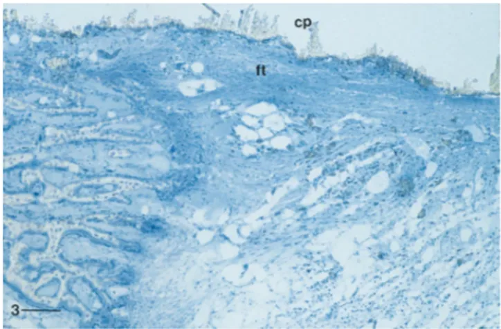
In one sample, the inner part of the cylinder was surrounded by a thin layer of cellular connective tissue (Fig. 3).
A few mineral grains had become detached from the implants and were found free in the connective tissue in the bone marrow cavities or even included within the
Fig. 1. Subperiosteal region of the cylinder (cp) in contact with newly formed bone trabeculae 2 weeks after implantation. The material was removed from the section by the microtome blade. Bar"300lm.
Fig. 2. Interface bone—material on the same section as in Fig. 1. Bone trabeculae (T) are apposed at the material surface and coated with osteoid tissue (P) lined with osteoblasts (P). Grains of material are found in the bone marrow cavity. Bar"100lm.
Fig. 3. Tissue—material interface in the mid-region of the same implant (cp) as in Fig. 1. The external part is in contact with newly formed bone tissue while the inner part is surrounded by dense connective tissue (ft) with collagen bundles parallel to the material surface. Bar"300lm.
bone matrix. Some of them had been phagocytosed into macrophages. These grains were round in shape and did not exceed 12lm in size.
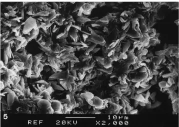
SEM showed that the material consisted of small white particles disseminated within a grey matrix with some micropores. Several grey-levels were visible in the matrix suggesting an unhomogeneous setting (Figs. 4 — 6).
The control bone defect was filled with loose connect-ive tissue in the form of a network with connectconnect-ive tissue trabeculae several tens of a micrometre in thickness. Ossification had begun at the edges of the defect.
3.1.2. After 6 weeks
One implant was almost degraded, with some frag-ments of a few hundred micrometres present and surrounded by immature bone trabeculae and un-mineralized osteoid tissue (Figs. 7—9). The amount and localization of this osteoid was unusual. Some calcium phosphate particles were found within the periosteum. A hyperplasic reaction of the periosteum had occurred. However, around these particles, no macrophage was evidenced.
Other implants showed a mineral core which still ap-peared as a solid. The region beneath the cylinder surface had been invaded by bone trabeculae. The bone marrow cavities between the trabeculae were completely filled with implant fragments. These fragments embedded within the bone tissue contained cells between the crys-tals. The bone trabeculae structure was immature with many remodelling marks. An organic matrix was visible in some sites at the implant surface. Many grains de-tached from the material were phagocytosed by macro-phages and gaint cells.
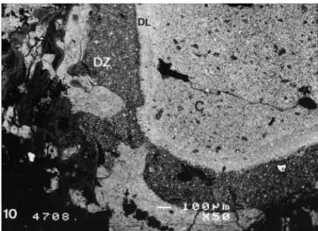
SEM revealed the presence of material fragments far from the implantation zone in the condyle. A dissolution zone of thickness 100 to 300lm could be observed under the material surface in one implant. Mineralizing bone trabeculae were ingrowing in this zone. The material core lined by this dissolution zone was edged by a densified layer less than 100-lm thick (Fig. 10).
The control defects were occupied by low-density tra-becular bone in which the bone marrow cavities con-tained cytologically normal marrow.
3.1.3. After 18 weeks
Small grains emitted by the material were less numer-ous in the bone marrow cavities surrounding the frag-mented materials. The remaining implants were fragmented with two or three big fragments totally lined by bone trabeculae parallel to the fragment surfaces. This lining bone layer was linked to the cortical bone by bone trabeculae.
The SEM showed that the material was a solid with pores ranging from a few to a hundred micrometres. White grains of different sizes ranging from one or two to several tens of micrometres were dispersed within a grey
Fig. 4. Backscattered SEM of a 2-week implanted cement (C). Very immature bone trabeculae (P) and bone fragments are in contact with the implant surface. The implant shows different grey levels due to different densities suggesting that the cement did not set homogene-ously after implantation. Some implant fragments are detached from the surface. Bar"1 mm.
Fig. 5. SEM of the section surface of an implant after 2 weeks showing interconnected crystals with pores within the matrix. Bar"10lm.
Fig. 6. Backscattered SEM of the section of a 2-week implanted cement showing white particles identified asb-TCP disseminated within a grey matrix with irregular porosity identified as DCPD. Bar"100lm.
Fig. 7. Fragments of a 6-week implanted cylinder (w) separated by bone trabeculae showing cemented lines ( ) probably indicating the start of the growth period. Bar"200lm.
Fig. 8. Implant fragments (w) embedded within immature bone 6 weeks after implantation. Most of the fragment volume contains cells whose nuclei are visible (blue dots). Bar"250lm.
Fig. 9. High magnification of the interface between the bone (j) and the mineral matrix (d). An organic matrix has invaded the matrix porosity. The grains are dissociated and the matrix is not mineralized. Bar"250lm.
Fig. 10. Backscattered SEM of the dissolution zone (DZ) principally affecting the DCPD matrix beneath its surface. The core of the cylinder (C) is lined with a densified layer (DL) of material. Bar"100lm.
Fig. 11. Backscattered SEM of a fragment of an 18-week implanted cylinder of microporous structure on which bone trabeculae are ap-posed. Bar"1 mm.
matrix (Figs. 11 and 12). Bone matrix showing different grey levels was in contact with the material. Some white particles could be found in the Havers canals and were probably grouped within the histiocytes. Some such par-ticles were included within the bone matrix.
The control zones were difficult to differentiate from the rest of the bone tissue. However, the low density of trabeculae in this region was characteristic of the control zone.
3.2. Histomorphometry
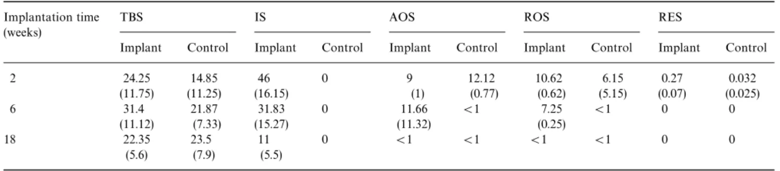
As shown by the implant surface (IS) measurements, the implant degraded during the implantation time Table 1. One quarter of the implant surface section re-mained after 18 weeks. During the first 6 weeks of im-plantation, there was a significant increase in the amount of bone trabeculae in the sites implanted with the cement
Table 1
Histomorphometric measurements made on the different sections expressed as a percentage
Implantation time TBS IS AOS ROS RES
(weeks)
Implant Control Implant Control Implant Control Implant Control Implant Control
2 24.25 14.85 46 0 9 12.12 10.62 6.15 0.27 0.032 (11.75) (11.25) (16.15) (1) (0.77) (0.62) (5.15) (0.07) (0.025) 6 31.4 21.87 31.83 0 11.66 (1 7.25 (1 0 0 (11.12) (7.33) (15.27) (11.32) (0.25) 18 22.35 23.5 11 0 (1 (1 (1 (1 0 0 (5.6) (7.9) (5.5)
Abbreviations: TBS, trabecular bone surface (BS/TS); IS, implant surface (IS/TS); AOS, active osteoid surface (Ob.S/BS); ROS, relative osteoid surface (OS/BS); RES, relative eroded surface (ES/BS).
Mean values with standard deviation in parentheses.
Fig. 12. Higher magnification of the bone—material interface observed by backscattered SEM 18 weeks after implantation. Some degradation marks (N) are visible at the material surface. The bone matrix shows different grey levels with the light grey zone having a very high cellular-ity characteristic of immature bone suggesting the occurrence of bone matrix ( ) maturation. Bar"100lm.
compared to the control sites. At 6 weeks, bone forma-tion as indicated by the active osteoid surface (AOS) and relative osteoid surface (ROS) measurements was still significantly higher in the sites implanted with cements than in the control sites.
4. Discussion
This study showed that:
f The cement set when injected into a bone marrow cavity and formed a porous calcium phosphate struc-ture.
f Two different calcium phosphate phases with different solubility rates could be identified by SEM observa-tion. The small white granules disseminated in the matrix were probably made of b-TCP granules be-cause the density (TCP"3.14) was higher than that of
DCPD (2.83). Furthermore the difference was in-creased by the TCP sintering during powder manufac-ture.
f A mild foreign-body reaction occurred in the vicinity of the material with a majority of mononucleated cells. Calcium phosphate particles were phagocytosed in these cells.
f The degradation rate of the material was relatively high when compared to the usual hydroxyapatite (HA) and TCP ceramics but compatible with the ingrowth of bone-forming trabeculae within the resorbing ma-terial.
Different fast-setting calcium phosphates have been described [3, 4, 8, 9—12] that all show osteoconductive properties and can be injected. These cements are gener-ally the product of an acid—base reaction. The reaction pH, which was not measured in this experiment, has proved to be low in vitro and did not seem to induce any necrosis as no dead tissue zone was visible 2 weeks after implantation. Ohura et al. [13] described the implanta-tion of a DCPD-based cement obtained from a mixture of MCPM (monocalcium phosphate monohydrated) and b-TCP to which calcium sulphate hemihydrate had been added. The samples were set during the intervention outside the body and implanted when solid. They con-cluded that these cements stimulated bone formation and were rapidly integrated by bone tissue.
In this experiment, the dissolution products induced a low foreign-body reaction. However, the presence of macrophages and gaint cells in the implantation site did not impair bone formation within the same site. Some differentiating osteoblasts synthesizing an osteoid matrix were identified among the macrophages. No increase in bone resorption could be detected at any time.
The ossification process occurring at the material con-tact was not identical to that taking place at the concon-tact of calcium phosphate ceramics. Osteoblast differenti-ation preferentially occurs at the calcium phosphate ce-ramic surface and leads to the presence of an osteoblast line which synthesizes an osteoid matrix and then an
immature bone. Once the material surface has been coated by an immature bone layer, the bone then extends to the entire pore volume.
In contrast, osteoblasts are not, or very rarely, found at the cement surface. Most of the osteoblasts differentiate at some distance from the cement and there is ingrowth of the forming bone trabeculae from the implantation cavity edges into the spaces made available by material resorp-tion. An interposition of a metachromatic matrix between some trabeculae and the cement during the early stages of implantation is in agreement with trabecular ingrowth. It is difficult to explain such differences in the ossifica-tion process. The high surface area of the material asso-ciated with the high solubility of the matrix could induce a microenvironment with a different physico-chemistry from that of the ceramic. The instability of the resorbing surface of the material could also have a role in these differences. The resorption could be too fast to allow bone apposition at the material surface.
5. Conclusions
This formulation gives a fast-setting calcium phos-phate showing ability to be replaced by bone tissue although a foreign-body reaction was detected. Setting was effective in a wet environment and particularly in bone. The degradation rate of the material was compat-ible with ingrowth of the bone tissue within the degrad-ing cement. The cylinders were degraded within a matter of weeks making it possible to use this matrix as a carrier for molecules under such physico-chemical setting condi-tions. The ossification process which took place at the material contact was different from that occurring at the ceramic contact.
References
[1] Dreesman H. Uber Knochenplombierung Beitre. Klin Chir 1892; 9:804 —807.
[2] Brown W, Chow LC. Combinations of sparingly soluble calcium phosphates in slurries and paste as mineralizers and cements. US Patent No. 4612053, 1986.
[3] Driessens FCM, Boltong MG, Bermudez O, Planell JA. Formula-tion and setting times of some calcium orthophosphate cements: a pilot study. J Mater Sci: Mater Med 1993;4:503— 508. [4] Driessens FCM, Boltong MG, Bermudez O, Planell JA, Ginebra
MP, Fernandez E. Effective formulations for the preparation of calcium phosphate bone cements. J Mater Sci: Mater Med 1994;5:164 —170.
[5] Mirtchi AA, Lemaı¨tre J, Munting E. Calcium phosphate cements action of setting regulators on the properties of theb-tricalcium phosphate—monocalcium phosphate cements. Biomaterials 1989; 10:634 — 39.
[6] Nancollas H. In vitro studies of calcium phosphate crystallisation. In: Mann S, Webb J, Williams RJP, editors. Biomineralization. Chemical and biochemical perspectives. New York: VCH, 1989:157—182.
[7] Parfitt AM, Drezner MK, Glorieux FH et al. Bone histomor-phometry: standardization of nomenclature, symbols and units. Report of the ASBMR nomenclature committee. J Bone Miner Res 1987;2:595— 610.
[8] Ishikawa K, Takagi S, Chow LC, Ishikawa Y. Properties and mechanisms of fast-setting calcium phosphate cements. J Mater Sci: Mater Med 1996;17:1429—32.
[9] Kurashina K, Kurita H, Hirano M, de Blieck JMA, Klein CPAT, de Groot K. Calcium Phosphate cement: in vitro and in vivo studies of the a-tricalcium phosphate—dicalcium phosphate dibasic—tetracalcium phosphate monoxide system. J Mater Sci: Mater Med 1995;6:343—47.
[10] Constanz BR, Ison IC, Fulmer MT et al. Skeletal repair by in situ formation of the mineral phase of bone. Science 1995; 267:1796—99.
[11] Bermudez O, Boltong MG, Driessens FCM, Planell JA. Develop-ment of some calcium phosphate ceDevelop-ments from combination of a-TCP, MCPM and CaO. J Mater Sci: Mater Med 1994; 5:160—63.
[12] Miyamato Y, Ishikawa K, Fukao H et al. In vivo setting behav-iour of fast-setting calcium phosphate cement. Biomaterials 1995; 16:855—60.
[13] Ohura K, Bohner M, Hardouin P, Lemaitre J, Pasquier G, Flautre B. Resorption of, and bone formation from, new b-trical-cium phosphate—monocalb-trical-cium phosphate cements: an in vivo study. J Biomed Mater Res 1996;30:193—200.
[14] Frayssinet P, Trouillet JL, Rouquet N, Azimus E, Autefage A. Osseointegration of macroporous calcium phosphate ceramics having a different chemical composition Biomaterials 1993; 14:423— 29.