HAL Id: hal-01900182
https://hal.archives-ouvertes.fr/hal-01900182
Submitted on 21 Oct 2019
HAL is a multi-disciplinary open access
archive for the deposit and dissemination of
sci-entific research documents, whether they are
pub-lished or not. The documents may come from
teaching and research institutions in France or
abroad, or from public or private research centers.
L’archive ouverte pluridisciplinaire HAL, est
destinée au dépôt et à la diffusion de documents
scientifiques de niveau recherche, publiés ou non,
émanant des établissements d’enseignement et de
recherche français ou étrangers, des laboratoires
publics ou privés.
System-Level Design and Virtual Prototyping of a
Telecommunication Application on a NUMA Platform
Daniela Genius, Ludovic Apvrille
To cite this version:
Daniela Genius, Ludovic Apvrille.
System-Level Design and Virtual Prototyping of a
Telecom-munication Application on a NUMA Platform. 2018 13th International Symposium on
Reconfig-urable Communication-centric Systems-on-Chip (ReCoSoC), Jul 2018, Lille, France.
�10.1109/Re-CoSoC.2018.8449375�. �hal-01900182�
System-Level Design and Virtual
Prototyping of a Telecommunication
Application on a NUMA Platform
Daniela Genius
Sorbonne Université, LIP6, CNRS UMR 7606, [email protected]
Ludovic Apvrille
LTCI, CNRS, Telecom ParisTech, Université Paris-Saclay, IMT, [email protected]
Abstract—The use of model-driven approaches for embedded system design has become a common practice. Among these model-driven approaches, only a few of them include the generation of a full-system simulation comprising operating full-system, code generation for tasks and hardware simulation models. Even less common is the extension to massively parallel, NoC based designs, such as required for high performance streaming applications where dozens of tasks are replicated onto identical general purpose processor cores of a Multi-processor System-on-chip (MP-SoC). We present the extension of a system-level tool to handle clustered Network-on-Chip (NoC) with virtual prototyping platforms. On the one hand, the automatic generation of the virtual prototype becomes more complex as topcell, address mapping and linker script have to be adapted. On the other hand, the exploration of the design space is particularly impor-tant for this class of applications, as performance may strongly be impacted by Non Uniform Memory Access (NUMA).
I. INTRODUCTION
Multiprocessor-on-chip system architectures
feature complex, sometimes hierarchical,
interconnect-on-chip architectures, allowing to
execute communication-centric applications such as telecommunication and video streaming. Usual
high-level UML/SysML-based model-driven
approaches target usual embedded applications and therefore they do not natively support such task-farm parallelism, neither from the application nor from the complex interconnection networks points of view. Thus, interconnection facilities are often limited to simple buses.
The task farm paradigm consists of a set of tasks waiting for data to be processed from one of the (many) common input buffers, thus introducing a high degree of non-determinism. On the contrary, embedded systems communications are typically one-to one, more rarely one-to-many e.g. broadcast. In order to explore designs for high-performance packet processing, virtual prototyping of clustered platforms has already been proposed in [8]. The task farm property was captured by writer multi-reader (MWMR) interfaces for channels mapped to shared memory, accessible by hardware or software tasks. Yet, the generation of platform variants was only semi-automatic and the middleware protocol lacked a formal basis.
In [11], we proposed a SysML based design methodology for task-farm applications on a flat interconnect. Only a simplified version of the ap-plication was handled, abstracting from I/O and internals (such as generation of descriptors, feed-back of addresses, inspection of packets). This paper proposes an extension in order to deploy and analyze the (nearly) complete application on NUMA architectures.
The paper is organized as follows. Section II presents the related work. Section III shortly in-troduces the System Level Design environment and explains our extensions. Section IV illustrates our approach with a case study. Section V discusses experimental results. Finally, section VI concludes the paper.
II. RELATEDWORK
During the software development process, soft-ware components are generally tested/executed on a local host, and only later integrated once the target is available. Software-hardware integration is postponed to the availability of the hardware target, often leading to late and costly revision on the software side. A more adequate approach is to frequently validate the different refinements of software components in an as-realistic-as-possible prototyping environment.
FPGAs can be used for this purpose [13], [14], but this requires to develop the hardware elements in detail, and to buy potentially costly FPGA.
Another promising, less costly, solution is the use of virtual prototyping platforms. Their obvious drawback is that software execution is commonly less realistic, and takes much longer wrt. FPGAs. Many fully software-based prototyping environ-ments have been proposed, some restricted to high-level analysis, others offering extended profiling capabilities.
PtolemyII [6] proposes a modeling environment for the integration of diverse execution models, in particular hardware and software components. If design space exploration can be performed, its first intent is the simulation of the modeled systems.
Metropolis [3], an extension of Polis, targets heterogeneous systems and offers various execution models. Architectural and application constraints are however closely interwoven.
Sesame [7] proposes modeling and simulation of features at several abstraction levels. Preexisting virtual components are combined to form a complex hardware architecture. In contrast to Metropolis, application and architecture are clearly separated in the modeling process. Currently, Sesame is limited to the allocation of processing resources to applica-tion processes. It neither models memory mapping nor the choice of the communication architecture.
MARTE [17] shares many commonalities with our approach, in terms of the capacity to separately model communications from the pair application-architecture. However, it intrinsically lacks sepa-ration between control aspects and message ex-changes. Other works based on UML/MARTE, such
as Gaspard2 [9], are dedicated to both hardware and software synthesis, relying on a refinement process based on user interaction to progressively lower the level of abstraction of input models. Still, such a refinement does not completely separate the application (software synthesis) or architecture (hardware synthesis) models from communication, which hampers exploration for NUMA platforms.
Di Natale et al. [5] propose the generation of communication managers for software low layers. Yet, they do not handle the specificity of task-farm applications nor they offer formal verification.
Batori [4] proposes a specific design method-ology for telecommunication applications. From use cases, the method proposes several formalisms to capture the application structure ("interaction model") and behavior (Finite State Machine) and for its deployment from which executable code can be generated. Design space exploration and virtual prototyping are not part of the methodology; code generation targets a real platform.
III. TTOOL
Our modeling framework is called TTool [1]. TTool relies on SysML to propose two abstract modeling levels: (i) HW/SW partitioning and (ii) software design and deployment [15]. From soft-ware deployment, a virtual MP-SoC prototype can be generated where software tasks run on multi-purpose processors.
TTool includes a tool chain for generating code — from software deployment diagrams — to be executed on SoCLib [16] based MP-SoCs as ex-plained in [10]. This toolchain thus takes as input a software design and a deployment of that design onto a hardware platform in order to generate a SoCLib representation. Basically, this tool chain works as follows:
• Each SysML block modeling a software task
is translated into an executable thread. The behavior of the block, expressed with state machine diagrams, is translated to a set of actions relying on C primitives defined in a runtime library.
• The main program instantiates the POSIX
chan-nels as software objects stored in on-chip memory.
• The top cell generator generates a SystemC
top cell for cycle-accurate bit-accurate simula-tion from the model of the HW architecture.
• The linker script is generated taking into
ac-count the mapping specified in the deployment diagram.
These four kinds of input necessary for SoClib are created by generators written in JAVA, profiting from a very powerful approach to generate code from SysML supported by TTool [2]. For topcell and linker script generation, the information con-tained in the mapping diagram is parsed. Where information is missing, default values are supplied where possible, otherwise a warning is displayed. Addresses are automatically calculated based on the number of clusters, of targets etc..
Up to now, TTool did not provide support for modeling multi-level interconnects and NUMA ar-chitectures. Inspired from [8], we propose a way to integrate clustered interconnect and NUMA in our SysML framework, and to automatically generate from the SysML diagrams the corresponding plat-form (HW and SW). To do so, we suggest to add the following features to TTool:
• Multi-level interconnects can be built up from
a (new) local crossbar modeling component and from the capacity to connect communica-tion components (e.g., crossbar, bus) together.
• The possibility to integrate I/O coprocessors.
• The definition and generation of more complex
topcelland ldscript in order to support the new
hardware elements listed above. A. Clustered Interconnects
A Virtual Generic Micro Network (VGMN), with a round-robin arbitration policy, or a Virtual Generic Serial Bus (VGSB) serve as central interconnect, and local crossbars connect the components within the cluster. Thus, the TTool deployment diagram of-fers the possibility to use crossbars, and to connect interconnect models with one another.
B. I/O Coprocesors
In order to extend communication capacities, we have also defined hardware coprocessors reading
packets from Ethernet connections. These coproces-sors are connected by MWMR wrappers. Yet, in an early design phase, hardware coprocessors are not yet available because they need to be designed in a precise way in SoCLib, i.e. directly in SystemC, but our approach focuses on the use of high-level modeling languages only. An option is to rely on software tasks capturing the behavior of the hard-ware coprocessors, but since they are mapped on general processors, they tend to falsify the results.
Currently, we suggest to rely on the SoCLib models from [8], called Input and Output Engine. The software design shows the channels with which they are connected to the other (software) tasks, while the deployment diagram contains the I/O engines for the generation of the virtual platform with HW coprocessors.
C. Generation of Topcell and Ldscript
SoCLib is based on the shared memory paradigm. The SoCLib mapping table is a centralized descrip-tion of both the address space segmentadescrip-tion and the mapping of the segments on the VCI physical targets. It is described in the topcell. When gener-ating the topcell from the deployment diagram, we first detect if a clustered interconnect is present. If this is the case, we automatically generate a two level mapping table by determining the number of segments and their size. The size of the data items and the maximum depth of the channel determine the size of the allocated memory.
IV. CASESTUDY
We consider a parallel telecommunication ap-plication, where all tasks of level n can read the data output by all tasks of level n − 1. Network packets are initially cut into chunks of equal size by the input coprocessor. Each packet chunk has a
descriptorreferencing the address of the next chunk
and containing some additional information. Only 64 bit descriptors are sent through the channels: the packet chunks themselves are stored in on-chip or off-chip memory. We do not model the packet storage because it has no impact of the logical and physical channels of the classification application.
<<block>> Scheduling - packet : PacketDesc; ~ in from_queue_low(PacketDesc packet) ~ in from_queue_medium(PacketDesc packet) ~ in from_queue_high(PacketDesc packet) ~ out to_scheduler0(PacketDesc packet) ~ out to_scheduler1(PacketDesc packet) ~ out packet(PacketDesc packet) ~ in scheduledPacket0(PacketDesc packet) ~ in scheduledPacket1(PacketDesc packet)
<<block>> Sched0
- packet : PacketDesc;
~ out scheduledPacket0(PacketDesc packet) ~ in toScheduler0(PacketDesc packet)
<<block>> Sched1
- packet : PacketDesc;
~ out scheduledPacket1(PacketDesc packet) ~ in toScheduler1(PacketDesc packet) <<block>> Classification - packet : PacketDesc; - f1 = true : bool; - f0 = true : bool; - f2 = true : bool;
~ out queue_low(PacketDesc packet) ~ out queue_medium(PacketDesc packet) ~ out queue_high(PacketDesc packet) ~ in c0_to_queue_low(PacketDesc packet) ~ in c1_to_queue_low(PacketDesc packet) ~ in c2_to_queue_low(PacketDesc packet) ~ in c0_to_queue_medium(PacketDesc packet) ~ in c1_to_queue_medium(PacketDesc packet) ~ in c2_to_queue_medium(PacketDesc packet) ~ in c0_to_queue_high(PacketDesc packet) ~ in c1_to_queue_high(PacketDesc packet) ~ in c2_to_queue_high(PacketDesc packet) ~ in from_IE(PacketDesc packet) ~ out to_c0(PacketDesc packet) ~ out to_c1(PacketDesc packet) ~ out to_c2(PacketDesc packet)
<<block>> Classif2
- packet : PacketDesc; ~ out to_queue_low(PacketDesc packet) ~ out to_queue_medium(PacketDesc packet) ~ out to_queue_high(PacketDesc packet) ~ in from_classif(PacketDesc packet)
<<block>> Classif1
- packet : PacketDesc; ~ out to_queue_low(PacketDesc packet) ~ out to_queue_medium(PacketDesc packet) ~ out to_queue_high(PacketDesc packet) ~ in from_classif(PacketDesc packet)
<<block>> Classif0
- packet : PacketDesc; - nbPackets : int;
~ out to_queue_low(PacketDesc packet) ~ out to_queue_medium(PacketDesc packet) ~ out to_queue_high(PacketDesc packet)
~ in from_classif(PacketDesc packet) <<datatype>>PacketDesc - address : int; - date : int; <<block>> InputEngine - packet : PacketDesc; - address : int; - frequency = 24 : int; - priority : int; ~ out packet(PacketDesc packet) ~ in address(int address) ~ in bootstrap(int address) <<block>> OutputEngine - packet : PacketDesc; - address : int; ~ out address(int address) ~ in packet(PacketDesc packet)
<<block>> Bootstrap
- address : int; - counter = 16 : int; ~ out address(int address)
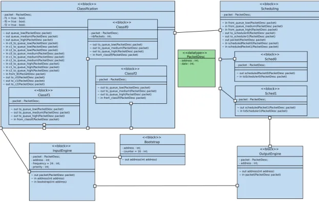
Fig. 1. Block Diagram of the classification application
• A bootstrap task organizes the system start-up
and fills the address channel with a set of ad-dresses generated from the adad-dresses available in packet memory.
• An input task reads one after the other the
addresses initially generated by the bootstrap task. Also, addresses freed from packets hav-ing left the system can be reused. Messages between bootstrap, input and output tasks cor-respond to 32-bit addresses. The Input Engine reads Ethernet encapsulated IP packets, cuts them into slots of equal size, and copies these slots to dedicated memory regions.
• A classification task reads one or several
de-scriptors at a time, then retrieves the first chunk of the corresponding packet from memory. Any classification task can access any chunk.
• The scheduling task reads one of the queues
according to their priority order, and then writes the descriptor to the output queue. Both
classification and scheduling tasks use try-read primitives to run as soon as data is available.
• The output task constantly reads the output
queue. Each time a slot is read, the output task frees corresponding addresses, and send them to the address channel for reuse.
Overall, the application task graph is thus inherently cyclic and very vulnerable to buffer overflows due to contentions.
Former work [8] proposed to map this applica-tion on a clustered interconnect. This work also included the definition of new hardware components in SoCLib to better handle I/O operations. Our contribution reuses these enhancements.
A. Software Design
Figure 1 displays the software design, using a SysML block diagram, of the telecommunication application. Addresses are represented by 32-bit integers. Packet descriptor are modeled as a data
type, containing an address and 32-bit of additional information.
The Input Engine reads addresses from the boot-strap task until the counter arrives at a preconfigured number. Then, when no more bootstrap addresses are available, the Input Engine uses addresses lib-erated meanwhile by the Output Engine. It then assigns a random number corresponding to the pri-ority - abstracting from a stream containing packets with IP addresses. The Input Engine works at a fre-quency which can be parametrized for exploration; if it is made to read packets too fast from Ethernet, buffers will overflow.
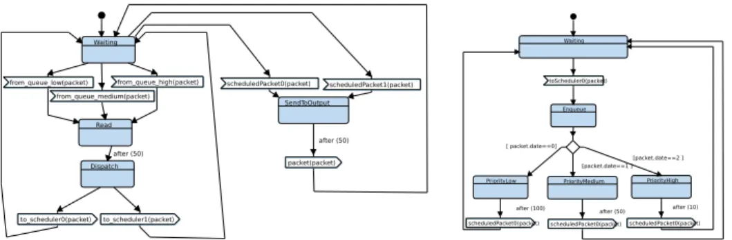
The classification tasks are represented in an hierarchical manner but, as the behavior is de-scribed much more precisely (packet inspection, non-arbitrary choice of the priority queue), they are far more complex than in [11]. All classification tasks write into one of three priority queues, cor-responding to three information signals exchanged on the central channel in the SysML block diagram. Figure 2 shows the rather complex state machines of the outer classification task. The non-deterministic dispatching of the descriptors read from the input queue and the retrieving of the descriptor as belong-ing to packets of low, medium, or high priority, as well as the dispatching to one of the three priority queues, is modeled in much more detail as in [11]. The scheduling tasks are also organized in a hierarchical manner. Each of them takes a descriptor as soon as it is available, and enqueues it after a waiting time depending on its priority. Figure 3 shows in the center and on its right the state machines of the outer and one of the two (identical) inner tasks, respectively.
The Output Engine receives descriptors from the channel shared by the scheduling tasks. A re-ordered flow of packets (in our abstracted model, descriptors are simply discarded) is then sent and freed addresses are fed back to the Input Engine. B. Architecture and Mapping
The target architecture features a two-level inter-connect based on a Virtual Generic Micro Network (VGMN), which behaves as two independent packet switched networks for commands and responses,
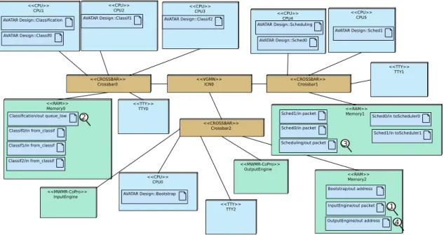
and three local crossbars, one per cluster. The I/O operations and the communication channels be-tween classification and scheduling tasks play a cru-cial role for investigating performance bottlenecks. Thus, we have extended deployment diagrams so that I/O tasks become explicit (Figure 4). Also, all functions (hardware, software) are now connected to the interconnect by MWMR wrappers.
V. EXPERIMENTS ANDRESULTS
The case study we present is known to suf-fer from several major performance impediments, such as overflow of the channels for high through-put, which can only be revealed once input and output hardware accelerators with parameterizable throughput are available. Our previous work could not capture these effects since our models were limited to the software part of the application only. A. Testbed
For virtual prototyping, hardware is described on CABA (Cycle/Bit Accurate) level, with high precision at the price of rather slow simulation. We perform simulations of the virtual prototype for three classifiers, three priority queues, and two schedulers and the initial mapping proposed in [8]. General purpose processors are SoCLib PowerPC 405 running at 433MHZ.
Hardware spies allow to log and analyze all traffic on the VCI interconnect. They are based on the
VCI_logger module proposed in SoCLib. Figure 4
shows how this spy mechanism, described in [12], is now integrated in the deployment diagram. These spies are represented in the form of magnifying glasses. The automatically generated topcell de-scribes the corresponding logger/statistics modules, relying on the name of the software objects to spy, derived from the TTool diagrams.
As we now model the (nearly) complete appli-cation, the generated platform should yield results comparable to the original one with 3 classifiers, 2 schedulers, no bursts and no packet memory access. B. Latencies
It is well known that memory access latencies for clustered platforms suffer a high standard de-viation with regards to usual platforms. Channels
Low queue_low(packet) c0_to_queue_low(packet) c1_to_queue_low(packet) c2_to_queue_low(packet) Medium queue_medium(packet) High queue_high(packet) c0_to_queue_medium(packet) c2_to_queue_medium(packet) c1_to_queue_medium(packet) c0_to_queue_high(packet) c1_to_queue_high(packet) c2_to_queue_high(packet) Low queue_low(packet) Waiting c0_to_queue_low(packet) c1_to_queue_low(packet) c2_to_queue_low(packet) Medium queue_medium(packet) High queue_high(packet) c0_to_queue_medium(packet) c2_to_queue_medium(packet) c1_to_queue_medium(packet) c0_to_queue_high(packet) c1_to_queue_high(packet) c2_to_queue_high(packet) WaitForPacket from_IE(packet) to_c0(packet) to_c1(packet) Waiting to_c2(packet) sendPacket recQueue [ f1] f2=false f1=false f0=true f2=true f1=true f0=true after (10,20) [ f2] [ f0] f0=false [else ] f0=true f1=true f2=true f0=true f2=true f1=true
f0=truef1=true f2=true [ f0||f1||f2] Waiting Waiting f0=true f1=true f2=true f1=true f2=true
Fig. 2. State machines of the outer classification task
Read to_scheduler1(packet) to_scheduler0(packet) from_queue_low(packet) from_queue_medium(packet) from_queue_high(packet) Waiting scheduledPacket1(packet) scheduledPacket0(packet) packet(packet) SendToOutput Dispatch after (50) after (50)
scheduledPacket0(packet) scheduledPacket0(packet) scheduledPacket0(packet) toScheduler0(packet) Waiting Enqueue PriorityHigh PriorityMedium PriorityLow [ packet.date==0] [packet.date==1 ] [packet.date==2 ]
after (100) after (50) after (10)
Fig. 3. State machines of the outer and inner scheduling tasks
are stored in memory, and the communications via these channels represented a high fraction of the application activity. The higher the number of tasks accessing a channel, the higher the amount of time spent waiting for the lock.
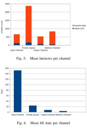
Spies for measuring the latency are placed on all four channels in Figure 4. Figure 5 shows the mean latencies for all four channels. They are about 30% faster than those of the original application but results are only partially comparable as we do not yet model packet memory accesses and IP address inspection.
The single input channel (InputEngine/out
packet, spyglass 1), mapped on the I/O cluster and accessed by the classification tasks from cluster 0 does suffer much less from high latency than the three priority queues (Classification/out queue_low, spyglass 2), mapped on Memory0 but written by three classification tasks and read by two scheduling tasks.
The graph also shows that the proportion of time to obtain a lock scales with the number of reader/writer tasks. Input and Output Engine being on the same cluster, the channel feeding back the addresses (OutputEngine/out address, spyglass 4) is less concerned by NUMA memory access, as
<<CPU>> CPU2 AVATAR Design::Classif1 <<CPU>> CPU3 AVATAR Design::Classif2 <<CPU>> CPU1 AVATAR Design::Classif0 AVATAR Design::Classification <<CPU>> CPU0 AVATAR Design::Bootstrap <<TTY>> TTY1 <<TTY>> TTY0 <<RAM>> Memory0 Classification/out queue_low Classif1/in from_classif Classif2/in from_classif Classif0/in from_classif <<RAM>> Memory1 Sched1/in packet Sched0/in packet Scheduling/out packet Sched0/in toScheduler0 Sched1/in toScheduler1 <<CPU>> CPU4 AVATAR Design::Scheduling AVATAR Design::Sched0 <<VGMN>> ICN0 <<CPU>> CPU5 AVATAR Design::Sched1 <<CROSSBAR>> Crossbar0 <<CROSSBAR>> Crossbar1 <<MWMR-CoPro>> InputEngine <<MWMR-CoPro>> OutputEngine <<RAM>> Memory2 Bootstrap/out address InputEngine/out packet OutputEngine/out address <<CROSSBAR>> Crossbar2 <<TTY>> TTY2 1 4 3 2
Fig. 4. Deployment Diagram with I/O cluster
expected. The Scheduling/out packet (spyglass 3), is even less concerned, even if descriptors have to transit from cluster 1 to cluster 2. Accordingly, standard deviations range from 214 for the priority queues to 61 for the output channel, which is still very high.
C. Buffer Fill State
Adding I/O coprocessors now also allows us to monitor the fill state of all channels of the original application, in particular InputEngine/out packet, known to suffer from overflows when the frequency of packet arrival increases. In the example shown here, we do not fix a frequency, addresses are read if they are available and there is space in the channel. The critical channel was dimensioned to hold 128 descriptors (1024 bytes), which proves sufficient here but will be too low when higher frequencies are imposed. Figure 6 shows the mean fill state of the channels, unsurprisingly low.
D. Discussion
Our overall results are rather close to the ones obtained with the original application and far more realistic than those obtained in [11] for only the software part, even though we do not model the access to packet memory on the one hand (to our advantage) and do not use burst transfers on the other (to our disadvantage). These two aspects remain to be added, but will not change results by orders of magnitude [8]. While the original modeling and deployment was a PhD thesis subject in itself, it took us little more than a week to write the models and do the evaluations shown here. The original application featured dozens of classification tasks; the design space was explored (using scripts) in order to determine the best number of and ation between classification and scheduling tasks for a given throughput. Currently, TTool block diagrams are limited by the fact that identical task replication cannot be represented.
Input Channel Priority Queue Output Channel Address Channel 0 500 1000 1500 2000 2500 transfer data obtain lock si m ul at io n cy cl es
Fig. 5. Mean latencies per channel
Input Channel Priority Queue Output Channel Address Channel 0 20 40 60 80 100 120 140 160 B yt e s
Fig. 6. Mean fill state per channel
VI. CONCLUSION ANDFUTUREWORK
We extend a UML/SysML virtual prototyping environment for SoCLib-based platforms with new modeling and evaluation capabilities for streaming applications. Our extensions are based on clustered interconnects and I/O elements. We are currently working on another extension of the tool which will enable us to compare highlevel simulation results -e.g., at partitioning - with results obtained with the virtual prototype. As high performance streaming applications usually feature a larger number of tasks, we will also add the possibility to describe and generate multiple identical tasks. Knowing well the results of former design space explorations for this particular application, we plan to use it as a particularly challenging test case for the explo-rations capabilities of our tool. Finally, we intend to enable the modeling and generation of Virtual Coprocessors from TTool descriptions, starting at partitioning level and handing these descriptions all the way down to the SoCLib virtual platform.
REFERENCES
[1] L. Apvrille. Webpage of TTool. In http://ttool.telecom-paristech.fr/.
[2] L. Apvrille. Ttool for diplodocus: An environment for design space exploration. In NOTERE’2008, Lyon, France, jun 2008.
[3] F. Balarin, Y. Watanabe, H. Hsieh, L. Lavagno, C. Passerone, and A. L. Sangiovanni-Vincentelli. Metropo-lis: An integrated electronic system design environment. IEEE Computer, 36(4):45–52, 2003.
[4] G. Batori, Z. Theisz, and D. Asztalos. Domain specific modeling methodology for reconfigurable networked sys-tems. In G. Engels, B. Opdyke, D. C. Schmidt, and F. Weil, editors, MODELS’07, pages 316–330. Springer, 2007. [5] M. Di Natale, F. Chirico, A. Sindico, and A.
Sangiovanni-Vincentelli. An MDA approach for the generation of com-munication adapters integrating SW and FW components from simulink. In MODELS’14, pages 353–369, 2014. [6] J. Eker, J. W. Janneck, E. A. Lee, J. Liu, X. Liu, J. Ludvig,
S. Sachs, Y. Xiong, and S. Neuendorffer. Taming hetero-geneity - the Ptolemy approach. Proceedings of the IEEE, 91(1):127–144, 2003.
[7] C. Erbas, S. Cerav-Erbas, and A. D. Pimentel. Multiob-jective optimization and evolutionary algorithms for the application mapping problem in multiprocessor system-on-chip design. IEEE Evol. Comp., 10(3):358–374, 2006. [8] Etienne Faure. Communications matérielles-logicielles
dans les systèmes sur puce orientés télécommunications. PhD thesis, UPMC, 2007.
[9] A. Gamatié, S. L. Beux, É. Piel, R. B. Atitallah, A. Etien, P. Marquet, and J.-L. Dekeyser. A model-driven design framework for massively parallel embedded systems. ACM TECS, 10(4):39, 2011.
[10] D. Genius and L. Apvrille. Virtual yet precise prototyping: An automotive case study. In ERTSS’2016, Toulouse, 2016. [11] D. Genius and L. Apvrille. System-level design for communication-centric task farm applications. In Re-CoSoC, pages 1–8. IEEE, 2017.
[12] D. Genius and N. Pouillon. Monitoring communication channels on a shared memory multi-processor system on chip. In ReCoSoC, pages 1–8. IEEE, 2011.
[13] K. Goossens, B. Vermeulen, and A. B. Nejad. A high-level debug environment for communication-centric debug. In Proc. DATE’09, pages 202–207, 2009.
[14] A. Kumar, A. Hansson, J. Huisken, and H. Corporaal. Inter-active presentation: An fpga design flow for reconfigurable network-based multi-processor systems on chip. In Proc. DATE’07, pages 117–122. EDA Consortium, 2007. [15] G. Pedroza, D. Knorreck, and L. Apvrille. AVATAR: A
SysML environment for the formal verification of safety and security properties. In NOTERE, Paris, France, 2011. [16] SoCLib consortium. SoCLib: an open platform for virtual prototyping of multi-processors system on chip (webpage). In http://www.soclib.fr.
[17] J. Vidal, F. de Lamotte, G. Gogniat, P. Soulard, and J.-P. Diguet. A co-design approach for embedded system modeling and code generation with UML and MARTE. In DATE’09, pages 226–231, April 2009.