Probabilistic Stability Analysis of Open Stopes in
Sublevel Stoping Method by Numerical Modeling
By
Shahriyar Heidarzadeh
A thesis submitted to l’Université du Québec à Chicoutimi in partial fulfillment of the requirements for the degree of Doctor of Philosophy in Earth and atmospheric sciences
Department of Applied Sciences, Université du Québec à Chicoutimi Saguenay, Quebec, Canada
ii
Abstract
Over the past years, maintaining the stability of underground excavations has grabbed attention
with the growing tendency of exploitation of deep underground mineral resources. Since sublevel
stoping is recognized as the most widely applied method in Canadian underground mines,
assessing the open stope stability develops concern for rock mechanics engineers over preserving
mining production capacity and providing safety for workers and equipment. Stress-induced
failure is among the most common causes of instability for underground open stopes. The
probability of failure (POF) depends on a number of factors including rock mass properties, in situ
stress state and stope geometry.
One of the most reliable approaches for evaluating the influence of the above mentioned factors
on open stope stability, is the use of probabilistic methods in conjunction with numerical analysis.
Various powerful probabilistic methods (e.g. Monte Carlo Simulation, Random Monte Carlo
Simulation and Response Surface Methodology) in conjunction with the finite difference code
FLAC3D have been applied throughout our research.
In fact, the present research provides a comprehensive methodology to perform a numerical
evaluation of the effect of open stope geometrical parameters (i.e., stope strike length, stope width,
and etc.) on the potential of rock mass brittle damage, as well as the probability of stope failure
(POF) by considering two modes of relaxation-related gravity driven (tensile) failure, and rock
mass brittle failure. Monte Carlo Simulation (MCS) and Response Surface Methodology (RSM)
are employed to determine the significant individual effects and their interactions of the geometric
parameters. This study applies geometrical parameters derived from a survey of numerous open
stopes from the Canadian Shield. Evaluation of the effect of stope geometry on the rock mass
iii
is observed for the stopes with moderate range of hanging wall hydraulic radius (HR) and high
range of hanging wall dip. While the lowest values of brittle damage is observed for the stopes
having low-moderate values of hanging wall HR and low-moderate values of hanging wall dip.
Also, the individual and interactive effect of stope geometrical parameters on the rock mass brittle
damage is found to be significant. Assessing of the effect of stope geometry on the probability of
tensile failure (POF) has pointed out that three parameters, which are the stope hanging wall HR,
stope span width and stope hanging wall dip, have a strong influence on the stope stability state.
Also it was found that the POF is significantly controlled by interaction effects between span width
/ hanging wall HR and hanging wall dip / hanging wall HR. Moreover, according to the results of
the mathematical optimization, the maximum stability (in terms of POF) occurs for shallow
dipping narrow stopes having large hanging wall HR. Whereas, the minimum stability would
happen in moderately to steeply dipping wide stopes with small hanging wall HR values.
Also, a probabilistic stability analysis was performed on seven primary open stopes located
in mining blocks V and VI at the Niobec underground mine (Saint-Honoré, Québec). Probabilistic
methods with the finite difference code FLAC3D, are employed to evaluate the stability state of
each studied stope, taking into consideration the inherent variability associated with the
geomechanical parameters of the rock mass. The stability state is defined via the tensile and
compressive probabilities of failure (POF) and the probability of brittle damage initiation (PDI).
Monte Carlo simulation generates the probabilistic rock mass input parameters while Random
Monte Carlo simulations applied a random spatial distribution of the geomechanical parameters
within the rock mass. The results indicate that for the evaluated open stopes, tensile and
iv
open stopes, no brittle failure is expected to occur under the existing conditions of rock mass
v
RÉSUMÉ
Pendant les dernières années, le maintien de la stabilité des excavations souterraines a attiré
l'attention avec la tendance croissante à l'exploitation des ressources minérales souterraines
profondes. Étant donné que la méthode des chantiers ouverts est reconnue comme la méthode la
plus largement utilisée dans les mines souterraines canadiennes, l'évaluation de la stabilité de ces
chantiers suscite des inquiétudes chez les ingénieurs en mécanique des roches quant à la
préservation de la capacité de production minière et à la sécurité des travailleurs et de l'équipement.
La rupture induite par la concentration des contraintes est l'une des causes les plus courantes d'instabilité pour les chantiers souterrains ouverts. La probabilité de rupture (POF) dépend d’un certain nombre de facteurs, dont les propriétés du massif rocheux, l’état de contrainte in situ et la
géométrie du chantier.
L’utilisation de méthodes probabilistes en conjonction avec l’analyse numérique est l’une des approches les plus fiables pour évaluer l’influence des facteurs susmentionnés sur la stabilité des chantiers. Diverses méthodes probabilistes ayant fait leurs preuves (par exemple, la simulation
de Monte Carlo, la simulation de Monte Carlo aléatoire et la méthodologie de surface de réponse),
associées au code de différences finies FLAC3D, ont été appliquées tout au long de la présente
recherche.
En fait, la présente recherche fournit une méthodologie complète pour effectuer une évaluation numérique de l’effet des paramètres géométriques des chantiers ouverts (c’est-à-dire la longueur du chantier, la largeur du chantier, etc.) sur le potentiel des dommages et la probabilité
de rupture du chantier (POF) en considérant deux modes de rupture, soit celle due à la gravité
vi
Carlo (MCS) et la méthodologie de surface de réponse (RSM) sont utilisées pour déterminer les effets individuels et d’interaction significatifs des paramètres géométriques. Cette étude applique des paramètres géométriques dérivés d'un inventaire de nombreux chantiers ouverts dans le
Bouclier canadien. L’évaluation de l’effet de la géométrie du chantier sur des dommages fragiles du massif rocheux indique qu’indépendamment de la profondeur des chantiers, les chantiers présentant un rayon hydraulique modéré et une pente élevée montre un plus grand dommage
fragile. Par contre, les chantiers avec les valeurs de rayon hydraulique du toit bas à modéré, et un
pendage de toit également bas a modéré montrent une dommage fragile minimal.
En outre, l’effet individuel et interactif des paramètres géométriques du chantier sur les dommages fragiles du massif rocheux s’avère significatif. L’évaluation de l’effet de la géométrie
du chantier sur la probabilité de rupture en traction a montré que trois paramètres, qui sont le rayon
hydraulique du toit, la largeur du chantier et le pendage de la paroi, ont une forte influence sur la
stabilité du chantier. Il a également été constaté que le POF est contrôlé de manière significative par des effets d’interaction entre la largeur du chantier / le rayon hydraulique du toit, et le pendage du toit / le rayon hydraulique du toit. De plus, selon les résultats de l’optimisation mathématique,
la stabilité maximale (en termes de POF) se produit pour les chantiers étroits peu profonds, à faible
pendage et ayant de fortes valeurs de rayon hydraulique du toit. Alors que la stabilité minimale se
produirait pour des chantiers larges et de pendage modéré à élevé, avec un toit ayant faibles valeurs
de rayon hydraulique.
De plus, une analyse de stabilité probabiliste a été est effectuée sur sept chantiers
principaux parmi les ouvrages souterrains situés aux niveaux V et VI de la mine souterraine Niobec
(Saint-Honoré, Québec). Les méthodes probabilistes utilisant le code de différences finies
vii
de la variabilité inhérente associée aux paramètres géomécaniques de la masse rocheuse. L'état de
stabilité est défini par les probabilités de rupture en traction et en compression (POF), et la
probabilité d'initiation de dégradation fragile (PDI). La simulation de Monte Carlo génère les
paramètres probabilistes du massif rocheux tandis que les simulations aléatoires de Monte Carlo
ont appliqué une distribution spatiale aléatoire des paramètres géomécaniques dans le massif
rocheux. Les résultats indiquent que pour les chantiers ouverts évalués, les ruptures de traction et
de compression partagent des POF similaires. Cependant, selon les valeurs de PDI autour de tous
les chantiers ouverts, aucune défaillance fragile ne devrait se produire dans les conditions
existantes de la qualité du massif rocheux et du régime de contraintes in situ aux niveaux V et VI
viii
Table of Contents
Abstract ... ii
Résumé ... v
Table of Contents ... viii
List of Tables ... xi
List of Figures ... xii
Dedication ... xv
Acknowledgment ... xvi
Contribution of Authors ... xvii
Chapter 1 - Introduction ... 1
1.1. Statement of problem ... 1
1.2. Research objectives ... 3
1.3. Research methodology ... 5
1.4. Originality and contribution ... 7
1.5. Thesis outline ... 9
Chapter 2 - Literature review ... 11
2.1. Sublevel stoping excavation method ... 11
2.2. Instability of underground excavations ... 12
2.2.1. Effect of stope geometrical parameter variations ... 17
2.2.2. Effect of uncertainties in the rock mass geomechanical parameters ... 20
2.2.2.1. Geological Strength Index (GSI)... 22
2.2.2.2. The generalized Hoek-Brown failure criterion ... 24
2.3. Stability analysis of an underground open stope ... 26
2.3.1. Probabilistic Approaches ... 30
2.3.1.1. Monte Carlo Simulation (MCS) ... 34
2.3.1.2. Random Monte Carlo Simulation (RMCS) ... 35
2.3.1.3. Response Surface Methodology (RSM) ... 35
ix Chapter 3 - Assessing the effect of open stope geometry on the rock mass brittle damage in
Canadian underground mines using response surface methodology ... 42
3.1. Abstract ... 42
3.2. Introduction ... 43
3.3. Methodology ... 47
3.3.1. Determination of rock mass parameters ... 48
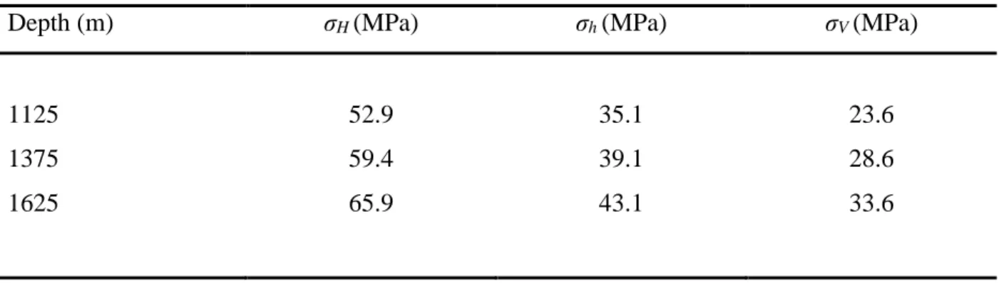
3.3.2. State of in situ stress ... 49
3.3.3. Determination of model geometry ... 51
3.3.4. Selecting a failure criteria ... 53
3.3.5. Experimental Design ... 54
3.3.6. Numerical Modeling ... 57
3.4. Results and discussion ... 59
3.4.1. Effects of geometrical parameters on BSR in cluster I ... 65
3.4.2. Effects of geometrical parameters on BSR in cluster II ... 68
3.4.3. Effects of geometrical parameters on BSR in cluster III ... 71
3.4.4. Stope geometry optimization corresponding brittle rock mass failure ... 74
3.5. Conclusion ... 76
3.6. References ... 77
Chapter 4 - Evaluation of the effect of geometrical parameters on the stope probability of failure in the open stoping method using numerical modeling ... 81
4.1. Abstract ... 81
4.2. Introduction ... 82
4.3. Methodology ... 85
4.3.1. Determination of rock mass parameters ... 86
4.3.2. State of in situ stress ... 88
4.3.3. Determination of model geometry ... 89
4.3.4. Selecting a failure criteria ... 92
4.3.5. Determination of the probability of failure ... 93
4.3.6. Numerical modeling ... 94
x
4.4.1. Effect of open stope hanging wall HR on the probability of failure ... 100
4.4.2. Effect of open stope span width on the probability of failure ... 103
4.4.3. Effect of open stope hanging wall dip on the probability of failure ... 104
4.4.4. Interaction effect of open stope geometric and inclination parameters on the probability of failure... 107
4.5. Conclusions ... 111
4.6. References ... 113
Chapter 5 - Use of probabilistic numerical modeling to evaluate the effect of geomechanical parameter variability on the probability of open stope failure: a case study of the Niobec Mine, Quebec (Canada) ... 116
5.1. Abstract ... 116
5.2. Introduction ... 119
5.3. Niobec Mine... 122
5.4. Methodology ... 124
5.4.1. Determining rock mass properties ... 125
5.4.2. Determining model geometry ... 129
5.4.3. State of in-situ stress ... 130
5.4.4. Selecting a failure criteria ... 133
5.4.5. Determining the probability of failure ... 134
5.4.6. Numerical modeling ... 135
5.5. Results and discussion ... 136
5.5.1. Evaluation of the probability of compressive and tensile failure ... 138
5.5.2. Evaluation of the probability of brittle damage initiation ... 146
5.5.3. Deterministic analysis... 151
5.6. Conclusion ... 153
5.7. References ………. 158
Chapter 6 - Conclusions ... 160
6.1. Assessing the effect of open stope geometry on the rock mass brittle damage ... 161
xi
6.3. Probabilistic evaluation of the effect of rock mass geomechanical variability on open
stope probability of failure ... 163
6.4. Perspectives for further research ... 164
Appendices …………...……….166
List of Tables
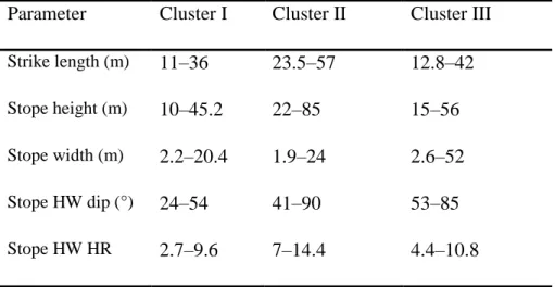
Table 3-1: The values of in situ stress components at three mining depths. ... 50Table 3-2: Stope geometry classes used in numerical modeling. HW: hanging wall. ... 52
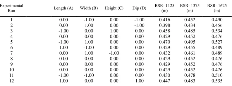
Table 3-3: Actual and coded values of the input parameters for each geometry class. HW: hanging wall.55 Table 3-4: Box–Behnken design matrix for Cluster I and response values at three depths. ... 55
Table3- 5: Box–Behnken design matrix for Cluster II and response values at three depths. ... 56
Table 3-6: Box–Behnken design matrix for Cluster III and response values at three depths. ... 57
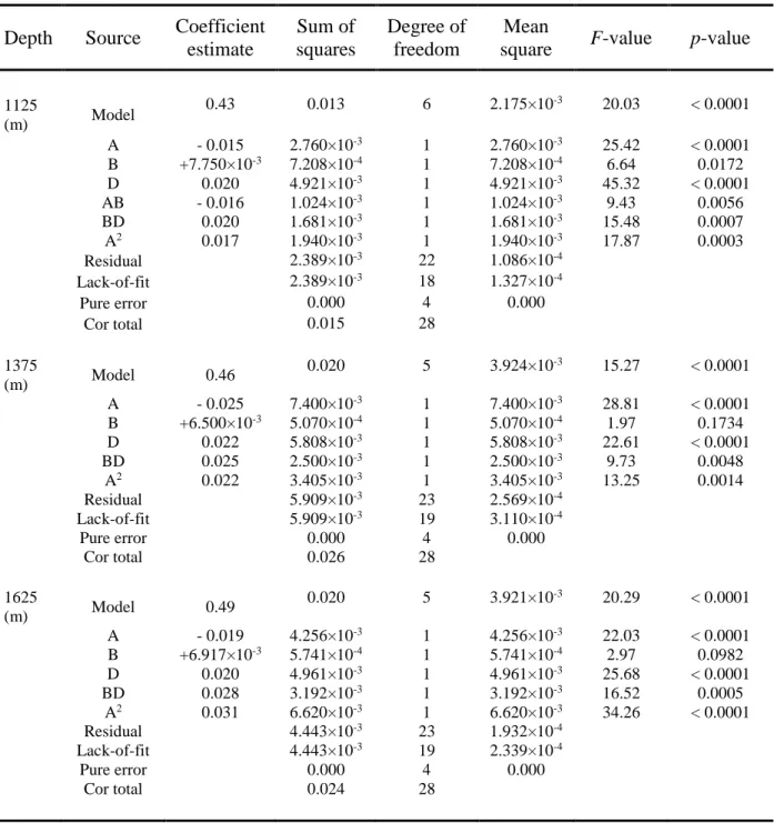
Table 3-7: ANOVA results of the regression model for Cluster I at three depths. ... 61
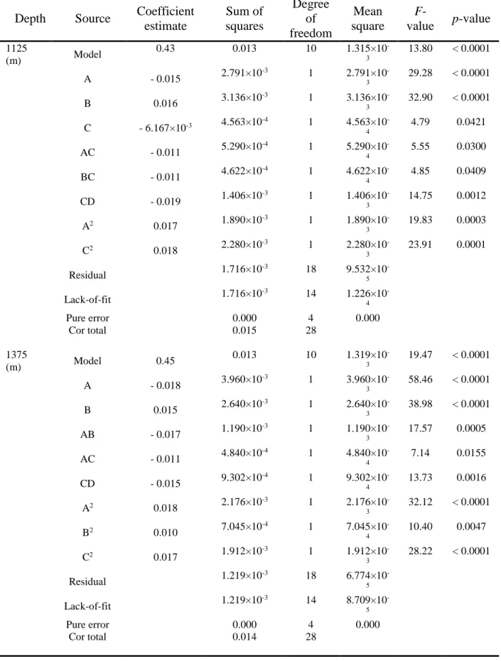
Table 3-8: ANOVA results of the regression model for Cluster II at three depths. ... 62
Table 3-9: ANOVA results of the regression model for Cluster III at three depths. ... 63
Table 3-10: The values of determination coefficient (R2), adjusted, and predicted determination coefficients. ... 64
Table 3-11: Numerical optimization of four independent variables and the responses based on the desirability value for three clusters at three mining depths. ... 75
Table 4-1: Intact rock properties. ... 86
Table 4-2: Rock mass geomechanical parameters. ... 87
Table 4-3: The values of in situ stress components. ... 88
Table 4-4: Stope geometrical categories the corresponding number of Monte-Carlo simulation for each category. ... 91
Table 4-5: The 36-full factorial experimental runs and the corresponding values of POF obtained from numerical modellings. ... 98
Table 4-6: ANOVA results of the regression model applied to POF data. ... 99
Table 4-7: The values of determination coefficient (R2), adjusted and predicted determination coefficients. ... 99
Table 5-1: Statistical moments for the intact rock parameters. ... 127
xii
Table 5-3: The range of values for the in-situ stress components. ... 132
Table 5-4: The mean values of minimum Hoek-Brown compressive and tensile safety factors (SF) and their associated probabilities of failure for each open stope. ... 144
Table 5-5: The mean values of maximum brittle shear ratio (BSR) and the associated probability of brittle damage initiation for each open stope... 150
Table of Figures
Figure 2-1- Schematic view – sublevel stoping method (Hustrulid 2001) ... 12Figure 2-2- Types of failure and instability problems in massive, moderately and highly fractured rock masses under low, intermediate and high in situ stresses (Adapted from Kelvis 2013). ... 13
Figure 2-3- (a) Spalling and slabbing around an excavation; (b) Potential of structurally-controlled gravity-driven failure (Adapted from Villaescusa 2014) ... 14
Figure 2-4- (a) Creation of the compression-induced tension cracking paralell to σ1; (b) Field-scale spalling to excavation walls; (Adapted from Diederichs 2004). ... 15
Figure 2-5- Schematic of strength envelope, presenting different rock mass failure mechanisms: no damage, shear failure, spalling, and unraveling. σc stands for the unconfined compressive strength (UCS) of intact rock (Adapted from Diederichs 2004) ... 16
Figure 2-6- Schematic of an open stope geometry and its associated geometrical parameters (Adapted from Wang 2004) ... 18
Figure 2-7- Geological Strength Index table for jointed rocks (Hoek 2007) ... 23
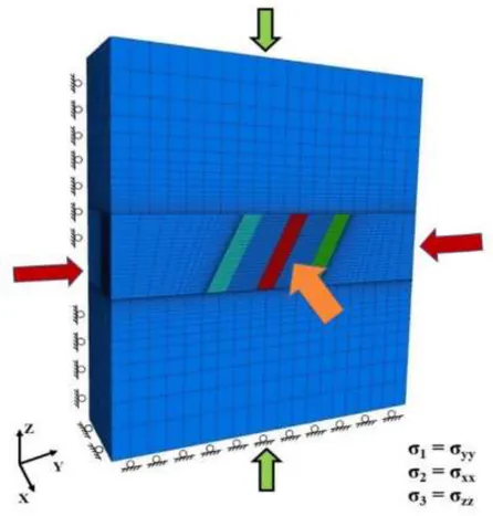
Figure 3-1 - Model boundary conditions and the state of in situ stresses. ... 58
Figure 3-2- Contour of maximum shear stress (Pa). ... 59
Figure 3-3- Contour of the brittle stress ratio (BSR). ... 59
Figure 3-4 - Response surface plots for geometry Cluster I. (a) interaction between width/length at mining depth 1125 m; (b) interaction between HW dip/width at mining depth 1125 m; (c) interaction between width/length at mining depth 1375 m; (d) interaction between HW dip/width at mining depth 1375 m; (e) interaction between width/length at mining depth 1625 m; (f) interaction between HW dip/width at mining depth 1625 m... 66
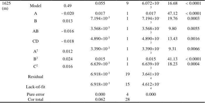
Figure 3-5 - Sensitivity analysis of the effect of stope strike length variation on (a) maximum and (b) minimum induced stress. ... 67
Figure 3-6 - Sensitivity analysis of the effect of stope hanging wall dip variation on (a) maximum and (b) minimum induced stress. ... 68
xiii Figure 3-7 - Response surface plots for geometry Cluster II. (a) interaction between height/length at mining depth 1125 m; (b) interaction between height/width at mining depth 1125 m; (c) interaction between HW dip/height at mining depth 1125 m; (d) interaction between length/width at mining depth 1375 m; (e) interaction between height/length at mining depth 1375 m; (f) interaction between HW dip/height at mining depth 1375 m; (g) interaction between length/width at mining depth 1625 m; (h) interaction between HW dip/height at mining depth 1625 m. ... 70 Figure 3-8- Effect of stope width variation on (a) maximum and (b) minimum induced stress ... 71 Figure 3-9 - Response surface plots for geometry Cluster III. (a) interaction between width/length at mining depth 1125 m; (b) interaction between HW dip/width at mining depth 1125 m; (c) interaction between width/length at mining depth 1375 m; (d) interaction between HW dip/width at mining depth 1375 m; (e) interaction between width/length at mining depth 1625 m; (f) interaction between HW dip/height at mining depth 1625 m... 72 Figure 4-2 - An open stope geometrical parameters (Adopted from Wang [2]). ... 89 Figure 4-3 - Distribution plots of (a) stope strike length, (b) stope height, (c) stope hanging wall HR, (d) stope hanging wall dip and (e) stope span width; for 150 open stope cases adopted from Wang [(Wang 2004)]. ... 90 Figure 4-4 - Model boundary conditions and the state of in situ stress. ... 95 Figure 4-5 - Contour of the brittle shear ratio (BSR). ... 96 Figure 4-6 - Contour of (a) minimum principal induced stress – σ3 (MPa), (b) minimum principal induced
stress – σ3 ≥ 0. ... 96
Figure 4-7 - POF plots for hanging wall HR variations for three average span width groups. (a) hanging wall dip range 20-45°; (b) hanging wall dip range 45-60°; (c) hanging wall dip range 60-75°; (d) hanging wall dip range 75-90°. ... 101 Figure 4-8- POF plots for span width variations for four hanging wall dip classes. (a) hanging wall HR range 2.5-5 m; (b) hanging wall HR range 5-7 m; and (c) hanging wall HR range 7-10 m. ... 104 Figure 4-9 - POF plots for hanging wall dip variation for three span width groups. (a) hanging wall HR range 2.5-5 m; (b) hanging wall HR range 5-7 m; (c) hanging wall HR range 7-10 m. ... 106 Figure 4-10 - General factorial analysis plots showing interaction effects between stope span width and stope hanging wall HR in (a) hanging wall dip range 20-45°; (b) hanging wall dip range 45-60°; (c) hanging wall dip range 60-75°; (d) hanging wall dip range 75-90°. ... 108 Figure 4-11 - General factorial analysis plots showing interaction effects between stope hanging wall dip and stope hanging wall HR for (a) span width of 4 m; (b) span width of 8 m; (c) span width of 12 m. .. 110 Figure 5-1 - Location of the Niobec Mine near Saguenay, Quebec (Canada) (Vallieres et al. 2013). ... 123
xiv Figure 5-2 - The methodology used to evaluate the effect of geomechanical variability of the rock mass on open-stope stability. ... 124 Figure 5-3 - The truncated normal probability distribution functions (PDFs) for (a) the uniaxial compressive strength (UCS) of the intact rock, (b) the geological strength index (GSI) of the rock mass, (c) the Hoek-Brown material constant mi, and (d) Young’s modulus Ei of the intact rock (data compiled by Lavoie 2018).
... 126 Figure 5-4 - The seven primary open stopes and the excavation sequence of mining blocks V and VI at the Niobec Mine... 130 Figure 5-5 - (a) Power trend curves applied to the calculated horizontal to vertical stress ratio K at various depths and (b) variations of the maximum and minimum horizontal in-situ stress components as the function of depth (after Lavoie 2018). ... 131 Figure 5-6 - The linear variation gradient of (a) the maximum horizontal in-situ stress component as a function of depth and (b) the vertical in-situ stress component as a function of depth. ... 132 Figure 5-7 - (a) & (b) The sectional views of generated numerical model containing the seven primary open stopes and (c) the plan view of the constructed numerical model containing the seven primary stopes. . 136 Figure 5-8 - Example of the random spatial distribution of (a) the Hoek-Brown “s” failure constant parameter and (b) the uniaxial compressive strength (UCS) of intact rock for a random seed. ... 138 Figure 5-9 - Normal probability density functions (PDFs) of the minimum Hoek-Brown compressive safety factor around the area of interest for each primary open stope. ... 141 Figure 5-10 - Normal probability density functions (PDFs) of the minimum Hoek-Brown tensile safety factor around the area of interest for each primary open stope. ... 143 Figure 5-11 - A plan view of maximum principal induced stress contours around open stopes and (b) a plan view of minimum principal induced stress contours around open stopes. ... 145 Figure 5-12 - The (a) profile view and (b) plan view of brittle shear ratio (BSR) contours around open stopes. ... 146 Figure 5-13 - Normal probability density functions (PDFs) of the maximum brittle shear ratio (BSR) value around the area of interest for each primary open stope. ... 149 Figure 5-14 - A plan view of maximum shear stress contours around the open stopes. ... 151 Figure 5-15- Outcomes from deterministic and probabilistic numerical analyses for (a) the minimum Hoek-Brown compressive safety factor and (b) the minimum Hoek-Hoek-Brown tensile safety factor. ... 152
xv
DEDICATION
This work is dedicated to my lovely family for their
kindness, devotion and endless support.
xvi
ACKNOWLEDGMENTS
I would like to express my sincerest appreciation to my supervisor Prof. Ali. SAEIDI, for his valuable supervision, his kindness, his permanent encouragement, and his important technical and financial support throughout this research.
I would like to express my gratitude to Prof. Alain. ROULEAU as my co-supervisor for his precious advices and his valuable suggestions throughout this research.
This research is financially supported by a research grant from the Natural Sciences and Engineering Research Council of Canada (NSERC) and a research grant provided by the Niobec Mine. I would like to thank them for their financial support.
I hereby appreciate all my professors, colleagues and friends at the department of Applied Sciences at the University of Quebec at Chicoutimi for their help and considerations along my journey.
Last but not least, I want to express my deepest appreciation to my mother Shiva, to my father Hassan, to my dear brother Kamyar and to my true friend Parinaz for their full support and endless love over all these years.
xvii
CONTRIBUTIONS OF AUTHORS
- Heidarzadeh S, Saeidi A, Rouleau A. Assessing the effect of open stope geometry on rock mass brittle damage using a response surface methodology. International Journal of Rock Mechanics and Mining Sciences. 2018; 106:60–73.
-
Heidarzadeh S, Saeidi A, Rouleau A. Evaluation of the effect of geometrical parameters on stope probability of failure in the open stoping method using numerical modeling. International Journal of Mining Science and Technology; 2018.-
Heidarzadeh S, Saeidi A, Rouleau A. Use of probabilistic numerical modeling to evaluate the effect of geomechanical parameter variability on the probability of open stope failure: a case study of the Niobec Mine, Quebec (Canada). Journal of Rock Mechanics and Geotechnical Engineering (Submitted)Conference papers:
- Heidarzadeh S, Saeidi A, Rouleau A. Numerical assessment of the effect of geometrical parameters on the stope probability of failure. Quebec Mines 2017 (Poster).
- Heidarzadeh S, Saeidi A, Rouleau A. Probabilistic evaluation of the effect of open stope geometrical parameters on the rock mass brittle damage. The 70th Canadian Geotechnical Conference, GeoOttawa 2017.
All the above mentioned articles are co-authored by Prof. Ali SAEIDI, as the
supervisor and Prof. Alain ROULEAU as the co-supervisor of the thesis.
1
Chapter 1 - Introduction
1.1. Statement of problem
During the recent decades, due to the shortage of easily minable near-surface mineral
deposits, the tendency to extract deep underground resources has been growing extensively in the
mining industry (Govett 1976; Potvin 2000). Therefore, maintaining the stability of underground
excavations has become a critical issue for underground engineers since it not only affects the
mining production capacity but also lowers the risk of fatalities and major financial loss (Einstein
1996; Idris 2011; Abdellah et al. 2014b).
Among numerous underground excavation methods, sublevel stoping is considered as the
most widely practiced technique in Canadian underground mines (Hudson 1993; Wang 2004;
Zhang and Mitri 2008; Abdellah et al. 2014b). Sublevel stoping creates large underground openings called “Stopes” whose level of stability is influenced by several factors including rock mass geomechanical parameters, natural and mining-induced stresses, and stope geometrical
parameters (Diederichs and Kaiser 1996; Chen et al., 1997; Henning and Mitri 2007; Idris et al.
2013; Villaescusa 2014). Underground instability and the probable failure conditions, for open
stopes located in deep hard rock, occur as a result of high magnitude mining-induced stresses. Low
confinement stress-induced failure consists of the two dominant modes, namely; (1) stress-induced
spalling and slabbing (brittle failure); and (2) structurally-controlled gravity-driven failures (i.e.
tensile) (Castro et al., 2012). Effects of these factors on different modes of stope instability, can
be assessed by using different analytical, empirical and numerical approaches. Among these
2
two methods (Idris 2014), therefore they are widely used to analyze the stability of underground
open stopes.
Although, numerical evaluation of the effects of stope geometrical parameter variations on
open stope stability has been investigated by several important studies (Chen et al. 1983, Germain
and Hadjigeorgiou 1997, Clark 1998, Henning and Mitri 2007); the aforementioned studies and
their corresponding assumptions present a number of drawbacks. First of all, the existing literature
provides many studies that investigate the effect of excavation geometry on low confinement
tensile (gravity-driven) modes of failure. However, in real conditions the occurrence of different
modes of stress-driven failure are possible therefore it would be more reasonable to consider
multiple possible failure scenarios when evaluating the state of stope stability. Even for a particular
instability mode, no comprehensive evaluation has been made to investigate the combined effects
of open stope size, shape and inclination on their state of stability. In other words, the previous
studies mainly focused on the effects of individual geometric parameters with limited variation
ranges (mostly case specific studies) while not considering the simultaneous variation of other
geometrical parameters. Therefore, in the case of studying the effect of stope geometry, the present
thesis attempts to provide a methodology to assess individual effects and their interactions of stope
geometrical parameter variations (considering typical stope dimensions in Canadian underground
mines) on multiple underground failure modes. The provided methodology uses different
probabilistic methods (e.g. Response Surface Methodology and Monte Carlo Simulation) in
conjunction with the finite difference code FLAC3D (Itasca 2015), to simulate a large number of
stopes, grouped in different geometric categories. Furthermore, mathematical optimization
techniques are employed to predict the most stable conditions for underground open stopes in
3
On the other hand, the effect of the geomechanical parameters of the rock mass on stope
stability is recognized to be significant and not negligible. Due to the heterogeneous nature of a
rock mass, its physio-mechanical properties are intrinsically variable (Idris 2011). The
uncertainties associated with the inherent variability of the geomechanical parameters of a rock
mass cannot be captured and accounted for by conventional deterministic approaches. Hence,
appropriate probabilistic methods should be used to incorporate the effect of uncertainties
associated with the rock mass inherent variability in strength and stiffness characteristics.
Therefore, in the present thesis, different probabilistic methods (e.g. Monte Carlo Simulation and
Random Monte Carlo Simulation) are utilized combined with the finite difference code FLAC3D
(Itasca 2015) to evaluate the stability state of multiple neighboring stopes, taking into
consideration the inherent variability associated with the geomechanical parameters of the rock
mass. The probabilistic stability analysis has been applied on seven primary open stopes located
in mining blocks V and VI at the Niobec underground mine (Saint-Honoré, Québec), considering
different underground instability modes. Moreover, to clarify the role of the aforementioned
uncertainties on the different modes of instability, we use a deterministic numerical model
simulation to compare rock mass behavior under both a deterministic and a probabilistic stability
analysis.
The general and specific objectives of the thesis are presented in the following section.
1.2. Research objectives
The general objective of this thesis is to apply a stochastic evaluation of the role of open
4
different modes of open stope failure in the sublevel open stoping excavation method, using
numerical analysis.
The specific objectives of this study are summarized as follows:
Development of a comprehensive methodology for probabilistic evaluation of the effect of open stope geometry on the rock mass brittle damage by using the brittle shear ratio (BSR)
as stability indicator.
Employing an appropriate data clustering technique to assign realistic range of values to each open stope geometrical parameter in accordance to the common stope geometries
of Canadian underground mines
Applying the response surface methodology (RSM) to identify the significant individual and combined effects of open stope geometrical parameters on the rock mass brittle
damage.
Using the RSM optimization tools to obtain the most stable and the most unstable stopes in terms of brittle damage, by determining the optimum values of stope geometrical
parameters.
Development of a methodology to assess the individual and combined effects of stope geometrical parameters on the open stope’s “probability of failure” (POF) by considering
both relaxation-related gravity driven failure, and rock mass brittle failure modes.
Applying a general multi-level factorial analysis to determine the significant individual and interactive effects of open stope geometrical parameters accompanied by
5
mathematical optimization techniques to predict the most stable stope states (in terms of the POF)
by determining the optimal ranges for each geometrical parameter.
Quantification of the inherent variabilities associated with the rock mass geomechanical parameters, by determining their means, standard deviations and probabilitydensity functions.
Using the Random Monte-Carlo simulation (RMCS) tool in the finite difference code FLAC3D in order to incorporate spatial random distributions of rock mass geomechanicalparameters in numerical simulations.
Evaluation of open stope stability in terms of tensile and compressive probabilities of failure (POF) and the probability of brittle damage initiation (PDI), respectively by using theHoek-Brown tensile and compressive safety factor and the brittle shear ratio (BSR) as stability
indicators.
Probabilistic evaluation of the state of stability for the primary open stopes located in mining blocks V and VI at Niobec underground mine, by considering the inherent variabilityassociated to rock mass geomechanical parameters for the first time.
The adopted methodology to reach the mentioned general and specific objectives of the
thesis are presented in the following section.
1.3. Research methodology
The methodology used to meet the objectives of the thesis is summarized through the
6
instability, significant factors influencing the stability of underground open stops (e.g. stope
geometry and rock mass geomechanical parameters), common methods of stability analysis and
the probabilistic approaches which are used to handle the variability associated to geometric and
geomechanical parameters. The effect of open stope geometry on rock mass brittle damage is then
assessed using Response Surface Methodology (RSM) in conjunction with numerical analysis.
The assessment is accomplished through the determination of rock mass geomechanical properties,
state of in situ stress and realistic ranges of stope geometric parameters (based on the typical stope
dimensions in Canadian underground mines) as input parameters for numerical modeling. Due to
the wide range of values for each geometrical parameter in the database, we used cluster analysis
by K-means clustering technique to partition the data into groups to determine more appropriate
parameter variations. The evaluation continued by determination of the significant individual and
interaction geometrical parameters on rock mass brittle damage, as well as predicting the most
stable stope geometries by using RSM and mathematical optimization techniques.
As the next step, similar procedure is adopted to evaluate the individual and combined
effects of stope geometrical parameters on probabilities of tensile and brittle failure considering
different instability criteria. A Monte-Carlo simulation technique combined with the finite
difference code FLAC3D (Itasca 2015) are utilized to simulate 3600 numerical models consisting
of stopes divided into different categories of geometry setups. General multi-level factorial
analysis determined significant individual and interaction effects of geometrical parameters on
probability of failures for each geometric category. Mathematical optimization techniques are
ultimately used to predict the most stable stope states (in terms of the POF) by determining the
7
Lastly, probabilistic evaluation of the effect of rock mass geomechanical parameter
variability on different modes of underground stability is accomplished on multiple primary stopes
at mining levels V and VI at the Niobec Mine, Quebec, using numerical modeling. The variability
associated to rock mass geomechanical parameters are incorporated into numerical modeling by
using Monte Carlo simulation and Random Monte Carlo simulation methods; while the stability
around each open stope is evaluated by calculating the tensile and compressive probabilities of
failure, based on the Hoek-Brown tensile and compressive safety factor, and the probability of
brittle damage initiation (PDI), via the brittle shear ratio (BSR). Ultimately, by comparing
probabilistic numerical model results with those run using a deterministic numerical approach the
effect of variability of rock mass geomechanical parameters on stope stability is highlighted.
1.4. Originality and contribution
The novelty of this work in terms of the effect of open stope geometry on its state of
stability is to propose a comprehensive methodology to investigate on the significant individual
and combined effects of open stope geometrical parameters on various modes of underground
failure by using different probabilistic methods in conjunction with numerical analysis. Although
literature is rich of studies investigating the effect of excavation geometry on low confinement
tensile (gravity-driven) modes of failure, a literature review by the authors indicated that the
influence of open stope geometrical parameters on rock mass brittle damage (ultimately causing
spalling and slabbing failure) has not fully been studied yet. Moreover, the previous studies mainly
focused on the effects of individual parameters while not considering the simultaneous variation
of other geometrical parameters. Therefore, the aforementioned studies and their corresponding
8
specific, and the variation ranges for selected geometric parameters were limited. Therefore,
obtaining a comprehensive interpretation of the effect of selected geometric parameters on the
stope stability seemed to be difficult. Secondly, in previous studies, single or multiple parameter(s)
were evaluated individually, and therefore the interferences caused by variation of other stope
geometric parameters have been underestimated. Finally, in previous studies either
relaxation-related tensile failure or rock mass brittle mode of failure was selected to evaluate the state of
stability; however, in real conditions the occurrence of different modes of stress-driven failure are
possible depending on the applied in situ stress regime and rock mass geomechanical
characteristics. Thus, it would be more reasonable to consider all possible failure scenarios when
evaluating the state of stope stability. Therefore in this study, the probability of open stope failure
was also considered as the targeted stability indicator.
Besides, in terms of investigating the effect of rock mass geomechanical variability, the
novelty of this study is to employ appropriate probabilistic methods in conjunction with numerical
analysis to take into account the inherent uncertainties associated to the rock mass geomechanical
parameters in stability analysis. he applied methodology is also applied for stability evaluation of
several open stopes in multiple mining blocks at the Niobec underground mine for the first time,
as a test for it. Since in reality different modes of stress-induced failure have the possibility of
occurrence depending on the applied in situ stress regime and rock mass geomechanical
characteristics, a comprehensive stability analysis would necessitate adopting multiple failure
9
1.5. Thesis outline
This thesis resulted in three scientific journal articles which are presented in separate
chapters (Chapters 3,4 and 5). Each article chapter in the thesis includes an Introduction and a
Conclusion. In addition, a general statement of the problem accompanied with a brief but selected
literature review, as well as some of the thesis objectives and outlines as stated in this chapter.
Chapter 1 explains the statement of problems, and describes the research objectives and
the adopted methodology to reach the defined objectives, as well as the novelty of the research.
In Chapter 2, a summary literature review is presented on different modes of underground
instability, key parameters affecting the stability of underground open stopes and common stability
analysis techniques.
Chapter 3 provides a comprehensive evaluation of the effect of stope geometric parameters on the “Brittle Shear Ratio” (BSR) of the rock mass surrounding a stope for three different mining depths. A response surface methodology with a Box–Behnken Design in conjunction with the
finite difference code FLAC3D (Itasca 2015) is utilized to evaluate the individual and interaction
effects of aforementioned input parameters.
Chapter 4 presents a methodology to assess the individual and combined effects of stope geometric parameters on the “probability of failure” (POF) by considering realistic open stope dimensions existing in Canadian underground mines. The POF is calculated considering both
relaxation-related gravity driven (tensile) failure, and rock mass brittle failure mode. A
Monte-Carlo simulation technique combined with the finite difference code FLAC3D (Itasca 2015) are
utilized to simulate a large number of stopes, grouped in categories of stope geometry. The
10
using a general multi-level factorial analysis. Mathematical optimization techniques are ultimately
used to predict the most stable stope states (in terms of the POF) by determining the optimal ranges
for each geometrical input parameter.
In chapter 5 seven primary open stopes located in mining blocks V and VI at Niobec
underground mine (Saint-Honoré, Québec) are subjected to probabilistic stability analysis using
numerical modeling to investigate the effect of inherent variability associated to the rock mass
geomechanical parameters. Niobec underground mine has been selected as the case study, due to
its unique features in terms of open stope geometry setups, hard rock quality and reported minor
collapses and failures. Therefore, probabilistic methods are employed in conjunction with the finite
difference code FLAC3D (Itasca 2015), to evaluate the state of stability for each aforementioned
stopes, by considering the inherent variability associated to rock mass geomechanical parameters.
The stability state is defined as tensile and compressive probabilities of failure (POF) and the
probability of brittle damage initiation (PDI), respectively by using the Hoek-Brown tensile and
compressive safety factor and the brittle shear ratio (BSR) as stability indicators. Monte-Carlo
simulation is used to generate the probabilistic rock mass input parameters while Random
Monte-Carlo simulation would be utilized to perform one hundred numerical modeling realizations with
spatial random distributions of rock mass geomechanical parameters.
Finally in Chapter 6, conclusions, recommendations and perspectives of the future
11
Chapter 2 - Literature review
2.1. Sublevel stoping excavation method
Among numerous underground excavation methods, sublevel stoping is considered as the
most widely practiced technique in Canadian underground mines (Hudson 1993; Wang 2004;
Zhang and Mitri 2008; Abdellah et al. 2014b). Depending on the characteristics of the orebody
and the surrounding rock mass, stoping methods are classified into three general categories:
Unsupported methods, Supported methods and Caving methods (Tatiya 2005). Sublevel stoping
method is an Unsupported stoping technique, which is appropriate for fairly strong orebodies
having steep inclination and competent wall rock mass (Hustrulid 2001). This method creates large underground openings called “Stopes”, which are formed by vertically dividing the orebody into levels (Fig. 2-1). In this method, two nearby stopes are being separated by a rib pillar left in
between. The upper level is being protected by keeping a crown pillar at the top of the stope, while
the lower level is used to haul out the crushed ore. Also, the stope itself would be divided vertically
into a number of levels called sublevels, referring to the name “Sublevel stoping”. In sublevel
stoping technique, the shape of stopes and ore boundaries should be regular. For larger ore bodies,
the area between the hanging wall and the footwall is partitioned as primary and secondary stopes. Since the blast hole drills could be used to accomplish drilling, this method is also known as “blast hole stoping” (Hustrulid 2001).
12
Figure 2-1- Schematic view – sublevel stoping method (Hustrulid 2001)
Recognizing the sources of underground instability is the building block of stability
analysis since adopting reliable and efficient solutions for probability of failure estimations and
controlling damage requires a comprehensive knowledge of instability reasons. In the following
section, different modes of underground instability are presented.
2.2. Instability of underground excavations
Hoek and Brown (1980) identified four principal sources of underground instability
(illustrated in Fig. 2-2) which are described by Kelvis (2013) as follows:
i. “High rock stress failure associated with hard rock. This kind of failure can occur
e.g., when mining at great depth or for large excavations at shallow depth. Stress conditions for
tunnelling in steep mountain regions or in weak rock conditions can also result in stress-induced instability problems”;
13
ii. “Structurally controlled failure tends to occur in faulted and jointed hard rocks, in
particular when several joint sets are steeply inclined”;
iii. “Weathered and/or swelling rock failure often associated with relatively poor rock.
This kind of failure may also occur in isolated seams within an otherwise sound hard rock”; and
iv. “Groundwater pressure or flow induced failure, which can occur in almost any
rock mass. If this failure is combined with any of the other types of instability listed above, it could reach serious proportions”.
Figure 2-2- Types of failure and instability problems in massive, moderately and highly fractured rock masses under low, intermediate and high in situ stresses (Adapted from Kelvis 2013).
14
In the case of underground openings located in deep, hard moderately to highly fractured
rock mines or for a brittle rock mass context, the high magnitude of mining-induced stresses could
cause rock mass damage initiation and sometimes failure in the areas close to the excavation walls
(Diederichs 1999a; Castro et al., 2012; Shnorhokian et al. 2015). Failure as a generic term, could
be identified in many forms, i.e. plastic yielding, macroscopic boundary cracks, spalling or
complete collapse of the excavation (Idris 2014). Hence, recognizing the damage process and
subsequent failure modes plays an important role in assessment of underground stope instability.
In general, under low confinement conditions, stress-induced instability occurs by two dominant
processes, namely; (1) stress-induced spalling and slabbing failure (Fig. 2-3a), and; (2)
structurally-controlled, gravity-driven failure (Fig. 2-3b) (Castro et al., 2012).
(a)
(b)
Figure 2-3- (a) Spalling and slabbing around an excavation; (b) Potential of structurally-controlled gravity-driven failure (Adapted from Villaescusa 2014)
15
The damage process commences with the creation of extension micro fractures within the
intact rock bridges in the rock mass as a result of high compressive stress regime. These
compression-induced tension cracks normally tend to form parallel to the major principal induced
stress σ1 or more accurately, normal to minor principal induced stress σ3 (Fig. 2-4a). Accumulation
and propagation of these cracks finally leads to the development of macro-fractures and release
surfaces (Fig. 2-4b) (Diederichs 2004).
(a) (b)
Figure 2-4- (a) Creation of the compression-induced tension cracking paralell to σ1; (b) Field-scale spalling to excavation walls; (Adapted from Diederichs 2004).
For brittle rock masses, the result of the mechanics of tensile fracture accumulation and
propagation and the consequent failure modes can be represented by the strength envelope (Fig.
16
Figure 2-5- Schematic of strength envelope, presenting different rock mass failure mechanisms: no damage, shear failure, spalling, and unraveling. σc stands for the unconfined compressive strength (UCS) of intact rock (Adapted from Diederichs 2004)
As explained by Diederichs (2004), the rock is undisturbed below the ‘‘damage initiation threshold’’. In the case of gravity-driven, structurally-controlled tensile failure, tangential and radial stresses decrease drastically, creating an unconfined area, or a relaxation zone, around the
opening. Consequently, relaxation in the walls reduces the minor principal induced stress to zero
or less and creates tensile stress (Diederichs 1999a; Kaiser et al. 2000; Diederichs 2004; Castro et
al., 2012). It should be noted that, according to Kaiser et al. (2000), relaxation in excavation walls
is attributed to the reduction of tangential stresses (the major and/or intermediate principal stress)
parallel to the walls, not to the radial stress component which leads to low confinement (Henning
2007). In the case of spalling failure, when a stress path moves to the left side of the low
confinement zone, (into the zone marked ‘‘spalling failure’’ in Fig. 2-5), and goes beyond the
17
excavation walls undergoes a significant reduction, whereas the tangential stress increases to its
maximum, leading to spalling normal to the minor principal induced stress (Diederichs 2004).
Normally, the spalling-slabbing failure continues to a certain depth within the wall boundaries
creating notch shaped geometries.
Instability of an open stope is influenced by several factors such as rock mass
geomechanical parameters, natural and mining-induced stress state, and stope geometrical
parameters (Diederichs and Kaiser 1996; Chen et al., 1997; Henning and Mitri 2007; Idris et al.
2013; Villaescusa 2014). The literature is rich of studies which utilized different methods to
explain and evaluate the effects of aforementioned factors on different instability modes. In the
following sections, a brief review on previous important studies are presented.
2.2.1. Effect of stope geometrical parameter variations
Stope geometry plays a key role in defining the level of stability when it comes to stability
analysis issues. However, effect of stope geometry has been found critical by many authors
(Aglawe 1999; Zhang and Mitri 2008; Villaescusa 2014); detailed effect of these parameters on
stope stability has not been fully understood yet. Geometry of an open stope is defined through its
geometrical parameters such as stope strike length, stope span width, stope hanging wall dip and
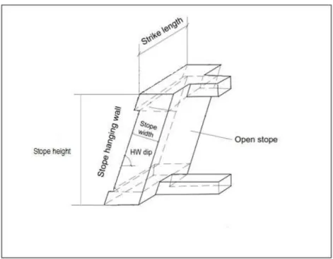
stope hanging wall size and shape (which is characterized by hanging wall hydraulic radius (HR))
(Fig. 2-6). The hydraulic radius (HR) is a parameter which is calculated for each exposed surface
of a stope while taking into account the combined effect of surface size and shape (Wang 2004;
Watson 2004). The hydraulic radius is also referred by the shape factor. The HR is calculated by
18 HR = 𝐴𝑟𝑒𝑎 𝑜𝑓 𝑡ℎ𝑒 𝑠𝑢𝑟𝑓𝑎𝑐𝑒
𝑃𝑒𝑟𝑖𝑚𝑒𝑡𝑒𝑟 𝑜𝑓 𝑡ℎ𝑒 𝑠𝑢𝑟𝑓𝑎𝑐𝑒 (2-1)
Figure 2-6- Schematic of an open stope geometry and its associated geometrical parameters (Adapted from Wang 2004)
Effect of open stope geometry (shape, size and inclination) on the state of stability, can be
evaluated by using different analytical, empirical and numerical approaches.
Almost all empirical stability analysis systems have addressed the effects of excavation
geometry on its stability (Germain and Hadjigeorgiou 1997). In tunnel design for instance, the influence of excavation’s height and width on its state of stability was studied by Terzaghi (1946) for the first time (cited by Germain and Hadjigeorgiou 1997). Similarly, the notion of unsupported
span and its stand-up time has been explained by Lauffer (1958) (cited by Germain and
Hadjigeorgiou 1997). Moreover, conventional rock mass classification systems (e.g. RMR, Q)
19
to excavation geometry (cited by Germain and Hadjigeorgiou 1997). Also, the effect of open stope
geometry in terms of hanging wall hydraulic radius (HR) or radius factor (RF) has been
incorporated in stability graph methods (Mathews 1981; Potvin 1988; Milne 1996; Wang 2004).
On the other hand, numerical analysis has been employed by many authors, mostly to
assess the effect of stope geometrical parameters on low confinement tensile (gravity-driven) mode
of failure. As a pioneering research, Chen et al. (1983) assessed the effect of open stope height by
applying finite element method and found it as a critical design parameter. Pakalnis et al. (1995)
reported that mining of narrow stopes increases the rate of instability. Milne (1997) linked the
hanging wall geometry of an open stope with measured deformation as an instability indicator and
successfully substituted the hanging wall HR with RF term in order to analyze more complex
geometries. Germain and Hadjigeorgiou (1997) defined an index for stope geometry by dividing
the volume of a stope and its real surface area (RVS) as a measure of stope geometrical complexity
to assess the applicability of the stability graph method. Clark (1998) introduced a new parameter
called ELOS (Equivalent Linear Overbreak or Slough) to evaluate the amount of dilution of a stope
hanging wall and reported that increasing the HR of the stope hanging wall contributes in
increasing the extent of hanging wall overbreak. Perron (1999) have shown that stope height and
geometry complexity adversely affect the stability of the hanging wall and suggested that stopes
having 60m height at the Langlois Mine be re-designed in order to reduce dilution (cited by
Henning and Mitri 2007). Aglawe (1999), concluded that the geometry of the excavations is
considered as the most significant factor influencing the occurrence of strainburst in highly
stressed ground. Wang (2004) developed a method to correlate stope geometry and induced stress
state through design graphs to evaluate stress relaxation related dilution. Afterwards, Wang et al.
20
by the aim of numerical modeling. Henning and Mitri (2007) assessed the effect of orebody dip
on the unplanned dilution and reported that shallower hanging wall dip caused more dilution due
to increasing the depth of overbreak. Hughes (2011) examined the effect of stope strike length on
ore dilution in narrow vein longitudinal mining by using finite element method and realized that
longer stope strike lengths generate larger volumes of dilution, while shorter strike lengths are less
prone to dilution. In recent studies, El Mouhabbis (2013) investigated the effects of stope geometry
on ore dilution and concluded that stope construction geometry has significant effect on overbreak
in a way that increasing stope strike length increases overbreak, shallower ore dip causes hanging
wall overbreak enhancement and finally narrow stopes exhibit higher dilutions.
In a review of previous studies, Villaescusa (2014) stated a general assumption that open
stopes with high vertical and short horizontal dimensions, and/or long horizontal and short vertical
dimensions have a higher degree of wall stability compared to square-shaped geometries, which
are considered to generate the most unstable open stopes.
As mentioned above, literature is rich of studies investigating the effect of excavation
geometry on low confinement tensile (gravity-driven) modes of failure. Nevertheless, a literature
review by the authors indicates that the influence of open stope geometrical parameters on rock
mass brittle damage (ultimately causing spalling and slabbing failure) has not fully been studied
yet.
2.2.2. Effect of uncertainties in the rock mass geomechanical parameters
The term rock mass refers to the assembly of intact rock material which is being separated
by different types of three dimensional discontinuities (Edelbro 2004, Idris 2014). In terms of
21
zero or negligible tensile strength, low shear strength and high fluid conductivity in comparison to
the intact rock material (Edelbro 2004). The intact rock itself has mechanical properties such as uniaxial compressive strength (UCS), tensile strength, Young’s modulus, etc. Thus, the rock mass geomechanical properties are defined based on the properties of both the intact rock materials and
the discontinuities (Idris 2014).
The aleatory uncertainty (inherent variability) associated with rock mass
physio-mechanical properties is a result of natural spatial randomness in the rock mass caused by the
geological processes (Nadim, 2007, Idris 2014). The existing aleatory uncertainty on one hand,
cannot be eliminated or reduced (Bedi and Harrison 2012) and on the other hand cannot be
neglected since it is reported (Idris 2014) to influence the rock mass behavior in terms of strength
and stiffness.
There are several approaches to estimate the strength and deformability parameters of
jointed rock mass which includes (Edelbro et al. 2007):
(i) Empirical failure criterion combined with rock mass classification systems;
(ii) Large-scale testing; and
(iii) Back-analysis of existing failures;
Among the above mentioned approaches, using empirical failure criteria in conjunction
with rock mass classification methods has received more attention due to their many advantages
including flexibility and simplicity (Edelbro et al. 2007).
Among the numerous developed rock mass classification methods such as RQD (Deere,
22
et al. 1974), the geological strength index (GSI) (Hoek et al., 1995) and the rock mass index (RMi)
(Palmström, 1995).tThe GSI method is considered as the only rock mass classification system
which has a direct link to engineering parameters such as Hoek-Brown strength and deformability
parameters (Cai et al. 2004). Since GSI method has been frequently used in this study to estimate
the rock mass geomechanical parameters. A brief summary of the method is presented in the
following subsections.
2.2.2.1. Geological Strength Index (GSI)
GSI rock mass classification system was introduced for the first time by Hoek et al. (1995)
in order to enable their generalized rock failure criterion to calculate the Hoek-Brown strength
parameters s, a and mb. The value of GSI for different types of rock mass is obtained by using the
GSI table (Fig. 2-7) which provides a qualitative description of the rock mass in terms of structural
quality (blockiness) and surface conditions (Hoek 2007). An important feature of the GSI system
is its easy application in the field since it uses the two key parameters of the geological process
named “the blockiness of the mass” and “the conditions of discontinuities”. Moreover, since both the RMR and the Q classifications use the RQD classification to rate the rock mass, and since the RQD value in most of the weak rock masses is either very small or considered meaningless, it became essential to develop an alternative classification system which not only eliminates RQD as an input parameter but also put greater emphasis on basic geological observations of rock mass.
Therefore, the new system not only reflects the material properties, structure and geological
history, but also is developed particularly to estimate the rock mass geomechanical properties
23
24
In fact, by having the GSI value of the rock mass accompanied by the values of the uniaxial
compressive strength of intact rock (UCS) and the petrographic constant mi, geomechanical
parameters of rock mass (such as the Hoek-Brown strength parameters (mb, s and a) and the
deformation modulus (Em)) can be determined using the equations provided by the generalized
Hoek-Brown failure criterion (Hoek 2007).
2.2.2.2. The generalized Hoek-Brown failure criterion
The general form of Hoek – Brown failure criterion is given by (Eqn 2-2):
σ1 = σ3 + σci (mb
𝜎3
𝜎𝑐𝑖 + s)
a (2-2)
Where σ1 and σ3 are the major and minor effective principal stresses at failure, respectively,
mb is the Hoek-Brown constant which reflects the characteristics of the rock mass, and σci is the
uniaxial compressive strength (UCS) of the intact rock sample. Rock mass constants (mb, s and a)
would be calculated by the following equations (Eqns 2-3 to2-5) (Idris 2014):
100 ( ) 28 14 e GSI D b i m m (2-3) 100 ( ) 9 3 e GSI D s (2-4) 20 15 3 1 1 ( ) 2 6 GSI a e e (2-5)
Where D is a parameter related to the degree of disturbance of the rock mass caused by
25
disturbed rock masses. By setting σ3 = 0 in equation 2-2, the uniaxial compressive strength of the
rock mass will be calculated as follow (Eqn 2-6) (Idris 2014):
a
cm cis
(2-6)
By setting σ1 = σ3 = σt in the equation 2-2 the tensile strength could be obtained (Eqn 2-7):
ci t b s m
(2-7)To calculate the deformation modulus of the rock mass Em (Eqn 2-8) (Idris 2014):
60 15 ( ) 11 1 2 (0.02 ) 1 rm i D GSI D E E e (2-8)
The required parameters for the Mohr-Coulomb failure criterion such as the friction angle,
the cohesion and the tensile strength for each rock mass can also be obtained, using the Eqns (2-9
and 2-10):
φ
= sin-1 1 3 1 3 6 ( ) 2(1 )(2 ) 6 ( ) a b b n a b b n am s m a a am s m (2-9) 1 3 3 1 3 (1 2 ) (1 ) ( ) 1 6 ( ) (1 )(2 ) (1 )(2 ) a ci b n b n a b n a s a m s m c am s mb a a a a (2-10)26
Where φ is friction angle, c is the cohesion and 3n is the normalized minor principal stress
and is equal to 3max
3n ci .
In the case of an underground excavation which is bounded by a zone of failed rock that
does not extend to the surface σ3max can be determined by using the following equation (Eqn 2-11)
(Idris 2014): 0.94 3max 0.47 cm cm H (2-11)
In the equation above, σcm refers to the rock mass strength, γ is the unit weight of the rock
mass and H is the depth of the excavation from the surface. If the horizontal stresses, has a higher
value than the vertical stress, the maximum horizontal stress value should be used instead of γH.
In the Canadian shield, the horizontal stresses are higher than the vertical stress and therefore, the
maximum horizontal stress is used instead of γH (Idris 2011b).
Due to the presence of the variability associated with the aforementioned rock mass
classification/characterization parameters, Hoek (2007) suggested to use random values (range of
values) as input for the Hoek-Brown-GSI method. Probabilistic methods provide solutions to
incorporate the uncertainty associated to the rock mass geomechanical parameters into stability
analysis of underground open stopes (Idris 2014). The application of probabilistic methods in
conjunction with numerical stability analysis is described in the following sections.
2.3. Stability analysis of an underground open stope
There are three groups of approaches commonly used to analyze the stability of
27
i. Analytical methods;
ii. Empirical Methods; and
iii. Numerical Methods.
For simple excavation geometries such as circular openings and two dimensional wedges,
the analytical methods are considered appropriate (Idris 2014). Applying an analytical method is
dependent on the analysis of a structural instability and rock-support interaction. In the structural
instability analysis, the shape and size of unstable wedges surrounding the structure, structure
geometrical characteristics (such as size shape and orientation) and discontinuity directions in the
region have to be taken into consideration. Since three-dimensional geometrical calculation of the
structure is time consuming and frustrating (Gharavi 2008), the analytical methods such as those
provided by Kirsch (1898), Ladanyi (1974) and Bray and Lorig (1988) (cited by Idris 2014) could
not be efficient enough for complex mining problems.
The empirical methods can be divided into two main categories: The first category utilizes
rock mass classification systems to rate the quality of the rock mass. Amongst the rock mass
classifications, RMR and Q methods are the most commonly used systems in stability analysis of
underground excavations (Gharavi 2008; Idris 2014). The second category is empirical
underground excavation design which analyses the stability of an excavation by combining the
geometry of excavation and the rock mass quality (Idris 2014). The most common method from
this category is the Stability Graph Method introduced by Mathews et al. (1981) and modified by
Potvin (1988) (cited by Idris 2014). The Q classification system is used in the stability graph
method; the effect of stress state, joint orientations with regard to excavation and the geometry of