To link to this article : DOI:
10.1007/978-3-319-45943-1_12
URL : https://doi.org/10.1007/978-3-319-45943-1_12
This is an author-deposited version published in: http://oatao.univ-toulouse.fr/
Eprints ID: 18132
O
pen
A
rchive
T
oulouse
A
rchive
O
uverte (
OATAO
)
OATAO is an open access repository that collects the work of Toulouse
researchers and makes it freely available over the web where possible.
To cite this version: Ge, Ning and Jenn, Éric and Breton, Nicolas and
Fontenneau, Yoann Formal Verification of a Rover Anti-collision System.
(2016) In: FMICS-AVoCS 2016, 26 September 2016 - 28 September 2016
(Pisa, Italy)
Any correspondence concerning this service should be sent to the repository administrator:
Formal Verification of a Rover Anti-collision System
Ning Ge1,*, Eric Jenn1,†, Nicolas Breton2, and Yoann Fonteneau2
1 IRT Saint-Exupéry, Toulouse, France [email protected] 2 Systerel, Toulouse, France [email protected]
Abstract. In this paper, we integrate inductive proof, bounded model check-ing, test case generation and equivalence proof techniques to verify an em-bedded system. This approach is implemented using Systerel Smart Solver (S3) toolset. It is applied to verify properties at system, software, and code levels. The verification process is illustrated on an anti-collision system (ARP for Automatic Rover Protection) implemented on-board a rover. Focus is placed on the verification of safety and functional properties and the proof of equivalence between the design model and the generated code.
Keywords: SAT, safety critical system, S3, bounded model checking, inductive
proof, equivalence proof, test case generation
1
Introduction
Even though significant progress has been made towards the integration of formal methods in the industry of safety critical systems, their usability is still impaired by their cost. Nevertheless, the hope is that once the initial integration is done, subsequent verifications can be achieved at significantly lower costs. In this paper, we show how this could be achieved using a formal verification toolset, Systerel Smart Solver (S3)3, and draw some lessons from our experience.
S3 [8] is built around a synchronous language and a model checker (S3-core) based on SAT [4] techniques. As the proof engine, S3-core relies on Bounded Model Checking (BMC) [3] and k-induction [16, 6] techniques. S3 supports different activi-ties of a software development process: property proof, equivalence proof, automatic test case generation, simulation, and provides necessary elements to comply with the software certification processes. It can be applied on designs expressed in SCADE [7]/Lustre [11] (including floating-point arithmetic) and implementations coded in C and Ada, and has been used for the formal verification of railway signaling systems for years by various industrial companies in this filed.
In this work, we apply S3 on an anti-collision system (ARP for Automatic Rover Protection) that is deployed on a three-wheeled rover. Focus is placed on three main activities: (1) Formal specification of the critical functional and safety requirements, (2) Verification of expected properties using appropriate formal techniques, (3) Proof
*Seconded from Systerel, Toulouse, France † Seconded from Thales Avionics, Toulouse, France
of the equivalence between the design model and the generated code. An additional purpose is to make the ARP use case publicly available to the research community. This paper is organized as follows: Section 2 presents the S3 toolset; Section 3 describes the ARP use case; Section 4 exposes the verification of safety and func-tional properties using inductive proof, BMC, and test cases generation techniques; Section 5 illustrates the process of equivalence proof for the verification of the gener-ated code; Section 6 draws some lessons from the verification activities, and Section 7 gives some concluding remarks and discusses perspectives.
2
The S3 Toolset
S3 is composed of the following main elements:
-- A synchronous declarative language similar to the Lustre language [11], called
HLL (High Level Language) that is used to model the system, its environment constraints as well as its properties. As an example, Fig. 1 presents an HLL model that calculates the population count (popcount) of an input boolean table of size N. The boolean elements of the input table are constrained to be conjunctively true. The function counter() is defined as the algorithm of popcount. Finally, the proof obligation clause expresses one expected property on the result. Constants: int N := 10;
Inputs: bool in[N];
Constraints: SOME i: [0, N-1] (in[i]); Declarations:
int unsigned 10 counter(int); int unsigned 10 cnt_num; Definitions:
counter(i) := if i == -1 then 0
else if in[i] then counter(i-1)+1 else counter(i-1); cnt_num := counter(N-1);
Outputs: cnt_num;
Proof Obligations: cnt_num <= N & cnt_num >= 1;
Fig. 1: Example of HLL Model
-- Several translators to convert models or code (Scade, Lustre, C and Ada) to
HLL models.
-- An expander to translate HLL models into a bit level language, called LLL (Low
Level Language) that only contains boolean streams and is restricted to three bitwise operators: negation, implication and equivalence.
-- A SAT-based proof engine, named S3-core, to check LLL models.
-- Tools to build equivalence proof between models, or between models and code. -- Tools to animate and debug models.
S3 supports the following activities of a typical development process:
-- Static detection of runtime errors and standard conformance check,
in-cluding array bounds check, range check, division by zero check, over and un-derflow check, output and constraint initialization check, etc. Proof obligations are also generated to ensure that the generated HLL models show no undefined behavior with respect to the semantics of the source language.
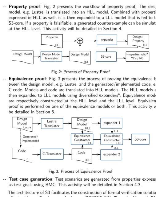
-- Property proof: Fig. 2 presents the workflow of property proof. The design
model, e.g. Lustre, is translated into an HLL model. Combined with properties expressed in HLL as well, it is then expanded to a LLL model that is fed to the S3-core. If a property is falsifiable, a generated counterexample can be simulated at the HLL level. This activity will be detailed in Section 4.
S3-core Design Model Design Model
Translator Design Model HLL
+
Propertie HLL expander Properties valid? YES / NO Design+ Property LLLFig. 2: Process of Property Proof
-- Equivalence proof: Fig. 3 presents the process of proving the equivalence
be-tween the design model, e.g. Lustre, and the generated/implemented code, e.g. C code. Models and code are translated into HLL models. The HLL models are then expanded to LLL models using diversified expanders4. Equivalence models
are respectively constructed at the HLL level and the LLL level. Equivalence proof is performed on one of the equivalence models or both. This activity will be detailed in Section 5. Design Model Lustre Code C Lustre Translator C-Translator Design Model HLL Code HLL expander 1 expander 2 Equivalence Constructor LLL LLL S3-core LLL Equivalence Constructor HLL Generated/ Implemented
Fig. 3: Process of Equivalence Proof
-- Test case generation: Test scenarios are generated from properties expressed
as test goals using BMC. This activity will be detailed in Section 4.3.
The architecture of S3 facilitates the construction of formal verification solutions compliant with certification standards, e.g. DO178C [10]. Towards this goal, S3 is organized in a set of small, independent components, from which the most critical ones - an equivalence model constructor, and a tool to verify the validity of the proof - are developed according to the highest integrity levels. The performance of the proof engine allows users to manage the proof of industrial size problems: the size of those models routinely attains ten millions variables and several hundred millions clauses. Verification of designs using floating-point arithmetic (FPA) compliant with IEEE Standard for FPA (IEEE 754) [1] are addressed by means of bit-blasting5 [8].
4The diversified expanders are designed and implemented by different teams using different programming languages.
5Bit-blasting is a classic method that translates bit-vector formulas into propositional logic expressions.
3
Specification and Design of the ARP Use Case
3.1 The Context of Use Case
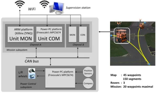
TwIRTee is a three-wheeled rover used to experiment and evaluate various meth-ods and tools in the domain of hardware/software co-design, virtual integration of equipments, and formal verification within the INGEQUIP project6. TwIRTee’s
ar-chitecture and its software and hardware components are representative of typical aeronautical, spatial and automotive systems [9]. The overall system is composed of a unique stationary supervision station and a set of TwIRTee rovers moving in a controlled environment (Fig. 4). The architecture of rover is composed of a mission and a power control subsystems. The power control subsystem is in charge of power supply, motor control and sensor acquisition. The mission subsystem is composed of a pair of redundant channels A and B. Each channel contains a monitoring unit (MON) in charge of monitoring the data and a command unit (COM) in charge of calculating commands for the rovers. The mission and power control systems communicate via CAN bus.
In the nominal case, each rover moves autonomously on a set of predefined tracks so as to perform its missions, i.e., moving from a start waypoint to a target way-point under speed and positioning constraints. In this system, the ARP function is aimed at preventing collisions between the rovers. It generates the maximal acceler-ations and minimal deceleracceler-ations that are taken into account by the rover trajectory management function. The communication between rovers are carried out via WIFI.
L/R wheels CAN bus Supervision station Power-PC platform (Freescale’s MPC5674) Position Sensors ARM platform (Xillinx ZYNQ)
Unit MON
WiFiUnit COM
Channel A Channel B MON Mission subsystem Power Control subsystem MON Compass CON Power-PC platform(Freescale’s MPC5674) Map : 45 waypoints
150 segments Rovers : 3
Mission: 20 waypoints maximal
Fig. 4: Overview of the TwIRTee System 6The INGEQUIP project is conducted at the IRT Saint-Exupéry.
Here, we introduce several terms used in the paper. A mission is defined by a list of waypoints to be “passed-by” by the rover. A segment, defined by a couple of waypoints on the track, corresponds to a straight path. Segments only intersect at waypoints. The set of all waypoints and segments constitutes a map. Dedicated monitoring mechanisms ensure that if the rover gets out of the track, it is placed in a stopped safe mode and the supervisor is alerted. Accordingly, we consider that all displacements of rovers comply with the map. In the use case, we consider 3 rovers moving on a map of 45 segments and 150 waypoints. A mission contains at most 20 waypoints.
3.2 System-Level Safety and Functional Requirements
The requirements of ARP use case comes from the industrial partners of the IN-GEQUIP project. The ARP is expected to ensure system-level safety requirement (REQ-SAF-1) stated in Table 2 in Appendix. REQ-SAF-1 states that at any time, the minimal distance between the centers of two rovers shall be greater or equal to 0.4m. It is split in two subsets of requirements: one about the exclusive access to segments (REQ-SAF-1-1) and several others about the design of map (IR-F1, IR-F2 and IR-F3). Compliance with the requirements of map data is under the map supplier’s responsibility.
Table 3 in Appendix presents other system-level requirements. The functional ones (REQ-F1 and REQ-F2) are mainly about excluding trivial implementations that would prevent collisions by, e.g., freezing all rovers. In the same manner, REQ-QoS-1 is introduced to guarantee the performance of the design, and to prevent trivial solutions of anti-collision, e.g., by performing missions sequentially. Note that the ARP is not to schedule the movement of the rovers but to ensure safety. Accordingly, if missions are schedulable, they shall remain schedulable with the ARP.
3.3 System Design Choice
Missions are elaborated off-line and transmitted via the supervision station. They are considered to be validated on-board (according to the REQ-F1 in Table 4 in Appendix). To ensure the main safety requirements, separation of rovers is imple-mented as follows: a rover may only enter a segment if it has been granted exclusive access to both the beginning and the end waypoints of the segment. As waypoints are global resources shared by all rovers, their reservation is ensured at system-level. Our system is designed as globally asynchronous and locally synchronous. Usually the synchronous programming schema used in synchronous languages, such as Lus-tre and HLL, supposes that time is defined as a sequence of instants. To preserve determinism, these languages use the concept of instantaneous broadcast [2] when several processes in parallel communicate, which means that message reception is synchronous (or simultaneous) with their emission. To comply with this execution semantics, we consider the PALS approach proposed in [15] where system-level clock synchronization is used to provide a global logical synchronicity.
3.4 High-Level Software Requirements and Software Design
During the software design process, the system-level requirements are refined into High-Level software Requirements (HLRs), given in Table 4 in Appendix. The HLRs represent "what" to be implemented, while the Low-Level Requirements (LLRs) represent "how" to implement it. In this work, the LLRs are expressed by a Lustre model7. For space reasons, the Lustre model is not presented in the paper. We briefly
describe some of its key points.
The ARP is split in two parts: one that manages segments reservation and one that calculates the speed and position of the rover with respect to the reservation decision. As mentioned in Section 3.3, the problem of reserving a track segment can be reduced to the problem of managing access to critical sections in a distributed system. In our design, this problem is solved by decomposing time into "time-slots" and allocating a dedicated reservation slot to each rover: so that only one rover at a time can perform a reservation. Each time slot is split in four sub-slots respectively for request, reply, reservation and empty tasks. For example, if there are two rovers (R1 and R2) in the system, the first time slot (sub-slots t0 - t3) is assigned to R1,
while the second time slot (sub-slots t4 - t7) is assigned to R2.
4
Property Verification
We have specified the system and produced a candidate Lustre design model in Sec-tion 3. Before generating C code from the Lustre model, one needs to check whether the model actually complies with its specification. With S3, this property verification process combines inductive proof, BMC, test case generation and equivalence proof techniques. The first three techniques are used to verify properties of the design model. The equivalence proof technique is used to verify that the generated code is equivalent to the model, which implies that the properties verified in the design model are also satisfied in the code. We illustrate the property verification in this section and present the equivalence proof in Section 5.
4.1 The Workflow of Property Verification
Fig. 5 presents the property verification workflow. The Lustre model is translated into an HLL model, to which properties and environment constraints expressed in HLL are concatenated. The full HLL model is then expanded to the LLL model used as the input of the S3-core. This verification workflow can be split in two phases: first, the properties are checked for a certain time length n. If no property is violated,
n is increased until either a counterexample (cex) is found, or some pre-known upper
bound of n is reached. In case a safety property8fails, a cex in the form of a sequence
of states is generated, where the last state contradicts the property. The cex trace is then directly exploited to debug the property or the design model.
7With respect to the DO178, the Lustre model is considered to express LLRs, since the source code is directly generated from the model with no other interpretation/refinement. 8Usually, the safety referred by requirements means the system is safe, while the safety
YES
HLL
Fig. 5: The Workflow of Property Verification
The BMC represents a partial decision procedure for a model checking problem, which is not complete. The completeness of a safety property can be achieved with k-inductive proof based on strengthening inductive invariants (also referred to as lemmas hereafter) if needed9. The k-induction relies on an iterative process to search
for lemmas by analyzing the repeatedly produced step counterexamples, until the proof is complete. Examples of k-induction proofs and BMC verification are given in Section 4.2 and 4.3 respectively.
4.2 K-inductive Proof of Safety Property
Recent works have shown that k-induction often gives good results in practice when implemented by SAT or SMT based model checking [16, 6]. Mathematical induction is the classical proof technique that consists of proving a base case (Eq. 1) and an inductive step case (Eq. 2). Let a transition systemS be specified by an initial state
condition I(x) and a transition relation T (x, x’) where x, x’ are vectors of state variables. A state property P (x) is invariant forS, i.e., satisfied by every reachable
state ofS, if the entailments in Eq. 1 and 2 hold for some k ≥ 0.
I(x0)∧ T (x0, x1)∧ · · · ∧ T (xk−1, xk)|= P (x0)∧ · · · ∧ P (xk) (1)
T (x0, x1)∧ · · · ∧ T (xk, xk+1)∧ P (x0)∧ · · · ∧ P (xk)|= P (xk+1) (2)
A counterexample trace for the base entailment indicates that the property P is falsifiable in a reachable state ofS. This is similar to the counterexamples produced
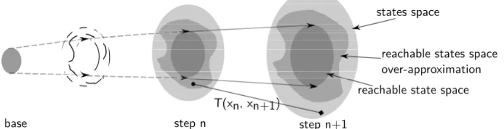
by BMC, but a counterexample trace for the induction step entailment may start from an unreachable state or an over-approximated reachable state ofS. In Fig. 6, we
distinguish the reachable part of the state space and the over-approximated reachable state space. The transition T (xn, xn+1) starts from an over-approximated reachable state in step n, and ends in a unreachable state in step n + 1. One way to rule out such step counterexamples is to increase the depth k of the induction. However,
some invariant properties are not inductive for any k. So, instead of increasing k, the method to enhance k-induction of a property is to strengthen the induction hypothesis using new lemmas to reduce the over-approximation of the reachable state space.
reachable state space reachable states space over-approximation states space
step n step n+1 base
Fig. 6: Step Counterexample in Inductive Proof
Many recent efforts are dedicated to the automatic generation of invariants (used as lemmas in this work): automatic invariant checking based on BDDs [14]; unbounded model checking using interpolation [12]; property-directed reachability (PDR) [5]; quadratic invariant generation using templates based on abstract inter-pretation [13]. S3 provides a lemma generation tool based on a speculation strategy that searches for equivalent variables at bit-level. According to our experience, it is still very difficult for those tools to generate all necessary lemmas for an arbitrary system, and manual elaboration of lemmas to complete the proof remains important. So, to keep the approach as generic as possible, we do not apply invariant generation methods. Instead, we show how lemmas can be found "manually" on the basis of the step-counterexamples. We pick the property HLR-06-1 in Table 4 as an example to illustrate the process of inductive proof.
Example 1. HLR-06-1 states that the rover position shall be in front of or at the initial position of the reserved area. It is formally expressed in Eq. 3, where, at time
t, posr(t) is the position of the rover r, and posr(initrsv, t) is the initial position of
the reserved area of rover r. The corresponding property expressed in HLL is given in Eq. 4, where i is the id of rover r, and the F LT _ge() is the floating point greater-or-equal operator. The notion of time cycle does not appear in Eq. 4, because it is implicit in the HLL model. To simplify the explanation, we suppose that the mission of each rover contains at most 5 waypoints.
∀r ∈ Rovers, t ∈ Time(posr(t)≥ posr(initrsv, t)
)
(3) FLT_ge(posi, init_rsvi) == true; (4)
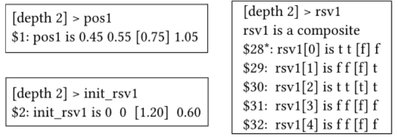
Following the workflow defined in Fig. 5, BMC is executed first, with no coun-terexample found within a time length of 20 cycles. Then k-induction is executed. With k = 1, a step counterexample is found in the next inductive depth (depth = 2), shown in Fig. 7. The FPA-lib of S3 follows the IEEE 754 FPA standard, thus
a variable of float type (here variables pos1 and init_rsv1) is composed of a sign, an exponent, and a mantissa. To facilitate the explanation, the converted decimal values of floating numbers are given in Fig. 7. The boolean variable rsv1[i] repre-sents the reservation status (by the local rover) of waypoint i of a rover's mission. Values of variables pos1, init_rsv1 and rsv1 are given for steps 0 - 3, where a step-counterexample is produced in step 2.
[depth 2] > rsv1 rsv1 is a composite $28*: rsv1[0] is t t [] f $29: rsv1[1] is f f [] t $30: rsv1[2] is t t [t] t $31: rsv1[3] is f f [] f $32: rsv1[4] is f f [] f [depth 2] > pos1 $1: pos1 is 0.45 0.55 [0.75] 1.05 [depth 2] > init_rsv1 $2: init_rsv1 is 0 0 [1.20] 0.60
Fig. 7: Step-counterexample of Property HLR-06-1
This step-counterexample contradicts the property HLR-06-1 because of pos1 (=0.75) < init_rsv1 (=1.20) in step k=2. This means that the rover locates out-side the reserved area. The reserved area is in fact a set of continuous10 reserved
waypoints of rover's mission, therefore the calculation of init_rsv1 depends on the reservation status of the waypoints (variable rsv1). We notice that in step k=1, the waypoints P0 and P2 in the mission are reserved (i.e., rsv1[0]=t and rsv1[2]=t), but the waypoint P1 is not (i.e., rsv1[1]=f), which means that the reserved area is not continuous. This step-counterexample does not indicate a design error. Indeed, REQ-09 in Table 4 requires that any positive reply to a reservation request shall contain a set of continuous waypoints. Unfortunately, we cannot use it as lemmas of this property because its inductive proof also produces step-counterexamples and needs to be analyzed. We thus have two solutions: (1) express and prove a property about the continuity of the reserved area, if valid, use it as a lemma to prove HLR-06-01; (2) investigate the step-counterexamples of HLR-09 to make it proved, and then use HLR-09 as a new lemma to prove HLR-06-1.
For the first solution, the added lemma is expressed in HLL as Eq. 5, where N is the number of waypoints in a mission. Using this additional lemma, HLR-06-1 as well as all other indeterminate11 properties are proved by 1-induction. In this case,
we suggest to report this step-counterexample to the designer. Then s/he might decide to add the new lemma as a complementary requirement about the continuity of reserved areas in the specification. This may reduce the re-verification effort.
ALL i : [0, N− 3], j : [2, N − 1] (rsv1[i] ∧ rsv1[i + 1] ∧ i + j ≤ N − 1 → rsv1[i + j]); (5) 10As explained by the REQ-01-4 in Table 4 in Appendix, we use continuous (continuity) hereafter for the fact that each waypoint has a unique precedent waypoint in a mission or in a reserved area, except that it is the initial one.
For the second solution, we can first consider HLR-09 as an axiom. Inductive proof demonstrates that even if HLR-09 were proved, HLR-06-1 would remain inde-terminate and a step-counterexample similar to the one in Fig. 7 would be produced again. Following the same idea, we assume all indeterminate properties except HLR-06-1 are valid, all the step-counterexamples indicate that the step k+1 contains non-continuous reserved areas. This leads the verifier to add the same lemma as the one in the first solution.
4.3 BMC and Test Case Generation
In general, properties are classified as safety or liveness properties. The former de-clares what should not happen (or should always happen), while the latter dede-clares what should eventually happen. The vast majority of properties in the ARP system are safety ones, except the system-level functional property REQ-F2 in Table 3 and the software-level functional property HLR-13 in Table 4.
Example 2. REQ-F2 states that at any time, if the definition of schedulable missions are free of deadlock, a deadlock shall not occur due to the ARP. HLR-13 states that the ARP shall ensure that the schedulable mission is completed within worst case mission time (WCMT).
HLR-13 is a bounded liveness property because an over-approximated WCMT can be used as the upper bound of checking. Hence it is a good candidate for BMC. If no counterexample12 is found before the time bound, the property is valid. In the
case of HLR-13, a counterexample is easily produced using BMC. A precondition of HLR-13 is REQ-F2, because a rover may not complete its mission when deadlocks occur. The validation of REQ-F2 requires that missions are schedulable, otherwise it is possible that deadlocks occur, and HLR-13 fails. As we cannot check these two properties considering the actual mission schedules, we use BMC to generate test case scenarios containing deadlocks due to unschedulable missions. These test cases can be used later to check the verification tool of mission schedules.
To explain the generation of deadlock scenarios, we consider a system with two rovers. REQ-F2 is satisfied if the property expressed in Eq.6 is false, where rovers ri and rj are stopped, ri (rj) requests waypoint pj (pi), but pi (pj) is reserved by ri (rj). Both rovers wait for a locked resource.
∀pi∈ Misi, pj∈ Misj, ri, rj∈ Rovers, t ∈ Time (i ̸= j ∧ state(ri, t) = STOP∧ state(rj, t) = STOP∧ req(ri, pj, t)∧ req(rj, pi, t)∧ rsvd(ri, pi, t)∧ rsvd(rj, pj, t))
(6)
We launch BMC for this property for some time length, and test case scenarios are extracted from the generated counterexamples.
12The counterexample of liveness property is a path to a loop that does not contain the desired state. This implies that with an infinite loop path, the system never reaches the specified state.
4.4 Safety Property and Map Data Validation
Some safety properties can hardly be verified by induction or BMC, in particular due to the floating-point operations for instance. In that case, we may take benefit of divide and conquer strategy by decomposing the property into a set of simpler ones, even static ones. Take the REQ-SAF-1 in Table 2 as an example.
Example 3. REQ-SAF-1 states that at any time, the minimal distance between the centers of two rovers shall be greater or equal to 0.4m.
This property can be verified by calculating the distance between two rovers at any time and then checking its value, unfortunately this solution is expensive. To alleviate this problem, REQ-SAF-1 is split in another safety property about the reservation of waypoints (REQ-SAF-1-1) and a set of properties about the map data (IR-F1, IR-F2 and IR-F3), see Table 2. REQ-SAF-1-1 is proved by k-induction. IR-F1, IR-F2 and IR-F3 are requirements about the length of segment, the distance between a waypoint and a segment, and the absence of intersection between segments. In this work, the map data are modeled in Lustre, as same as the software. Beside the advantage of using a unique toolchain, this approach allows to reuse directly the properties expressed on the map data in the verification process of the software. In fact, these static map data could be easily checked using a dedicated verification program. However, when these map properties are used as sub-properties of the safety property REQ-SAF-1, they need in any case to be re-verified in the Lustre model.
4.5 Property Verification Results
The safety, functional and performance properties of ARP are formally expressed in Table 5, Table 6 and Table 7 in the Appendix. As shown in Table 1, some safety properties can be directly proved by 0 or 1-induction, while some others need ad-ditional lemmas. REQ-QoS-1 is a system-level performance property. It is difficult to verify it at system-level without having software design, it is thus expressed as HLR-12 and verified at software-level by inductive proof.
Table 1: ARP Property Verification Results Verification
Techniques REQ-ID Verification Results
Inductive Proof
IR-F1, IR-F2, IR-F3, REQ-F1, HLR-01, HLR-03,
HLR-04, HLR-05, HLR-07, HLR-08, HLR-11 Valid by 0-induction
REQ-SAF-1-1, HLR-10 Valid by 1-induction
02, 06-1, 06-2, 06-3, HLR-06-4, HLR-09, HLR-12 (REQ-QoS-1)
Valid by 1-induction us-ing additional lemmas Data Validation REQ-SAF-1 (IR-F1, IR-F2, IR-F3) Valid
BMC and Test
5
Equivalence Proof between Design and Generated Code
The property verification activities depicted in Section 4 demonstrate that the design model complies with its specification. However, there is still a gap between the design model and the code embedded in the system. The code can be either implemented by the developer or be generated automatically from the Lustre model. In our case, we use the lus2c translator13 to generate the C code from the Lustre model. However,as this translator is not qualified14, it is still unknown whether this C code satisfies
the specification.
To prove the code is correct, two approaches are applicable. The first one fol-lows the strategies presented in Section 4. We first translate the C code into the HLL model using a C2HLL translator, and verify that this HLL model satisfies all requirements defined in Section 3. The second approach demonstrates that the code is equivalent to the design model, i.e., the same inputs generate the same outputs. This guarantees that the properties (related to inputs and outputs) satisfied by the design model will be satisfied by the code.
Fig. 8 presents several verification activities (A) in the process of equivalence proof: A1 generates C code from Lustre model with a qualified translator; A2 trans-lates Lustre models into HLL models, where properties are combined and verified; A3 translates C code into HLL models, where properties are combined and verified; A4 proves that the HLL models generated from the Lustre model and the C code are equivalent; A5 proves that the LLL models generated from the Lustre model and the C code (through the HLL model) are equivalent.
Fig. 8: Activities in the Process of Equivalence Proof
Based on different development contexts and the activities in Fig. 8, we summa-rize a set of strategies (S) for the verification of the C code, as follows:
13The translator lus2c is provided by Lustre v4 toolset. 14Qualification is a requirement in getting a system certified.
-- S1: The code generator is qualified as a development tool at the same level as
the application. Properties are verified on the Lustre model (A2). Thanks to the qualified translation (A1), properties are preserved in the generated C code.
-- S2: The code generator is not qualified at the same level as the application.
• S2a: Properties are directly verified on the C code (A3).
• S2b: Properties are verified on the Lustre model (A2). The C code is proved
to be equivalent to the Lustre model (A4 or A5). Thanks to the equivalence proof, properties are preserved by the C code.
* S2b1: The equivalence is proved at HLL level (A4). * S2b2: The equivalence is proved at LLL level (A5).
• S2c: Properties are verified at both Lustre and C code level (A2 and A3).
We prove equivalence between the Lustre model (including the map data) and the generated C code. In our case study, we applied the strategy S2b for the following reasons:
1. The C code generator lus2c is non-qualified. (rule out S1)
2. It is reasonable to assume that only a subset of the requirements will be formally expressed and verified. One will probably use other more classical approaches, such as testing. The cost of test increases as the abstraction level decreases, thus test is less expensive at Lustre level than at C level. (rule out S2a and S2c) 3. Specific formal verification techniques can be applied on Lustre thanks to its abstract semantics, which is lost once the C code is generated. This implies that proving properties at Lustre level is simpler than at C level. (rule out S2a and S2c)
4. S2b supports two complementary approaches of equivalence proof S2b1 and S2b2. S2b1 allows debugging counterexamples at the HLL level, but might need additional lemmas for some cases. S2b2 automatically searches and adds neces-sary lemmas using speculation techniques, but counterexamples are still difficult to exploit. Usually S2b2 is performed first; if a property is falsifiable or indeter-minate, the S2b1 is used to analyze the (step-)counterexample. (keep S2b)
6
Lessons Learned
6.1 Proof of Generated Code
The strategies of equivalence proof discussed in Section 5 have pros and cons. One can select appropriate strategies under the development contexts and the available resources.
-- S1 requires a qualified code generator. This was not an option in our case, but
this is the usual strategy in the domain of safety critical applications where the cost of a failure largely exceeds the cost of qualification. A qualified code generator saves a lot of effort, but is very expensive.
-- S2a and S2c require to express and verify properties and lemmas at code level.
As the code is less abstract and more complex than the Lustre model, property verification requires more effort.
-- S2c seems redundant as property proofs are performed at both Lustre and C
level. However, it might be useful to determine the origin of an error: a property satisfied in Lustre but falsifiable in C reveals probably an error during translation.
-- S2b is "S1 without qualified generator". The equivalence proof between Lustre
model and C code ensures that the generated C code implements exactly the properties expressed in Lustre. S2b does not need expensive qualified generator, but needs more effort to carry out equivalence proof. Each time the Lustre model is modified and the new code is generated, the equivalence needs to be re-proved.
6.2 Proof-Driven Design Guidance
The formal verification of a system could fail because of the complexity of the system, the lacking of complete requirements to support formal verification, etc. For instance, in Section 4.2, the HLR-06-1 is proved by k-induction after searching and adding a lemma. If we consider that the verifier has not a complete or deep knowledge about the design, s/he reports a scenario that contains the step-counterexample to the designer. If necessary, the designer may then decide to add a complementary requirement derived from this lemma in the initial specification, in order to reduce the cost of subsequent verification. The other way round, the verifier may ask the designer to state as many detailed requirements as possible about the system. These properties may be written as comment and/or assertions to be checked at runtime. Sometimes, a lemma may not be provable from the initial hypotheses. This might be the case that some environment hypotheses have been considered as granted by the designer without ever being explicitly expressed. This case could be handled either by a modification of the requirements to make the hypothesis explicit or by a modification of the design to make it independent from these hypotheses.
7
Conclusion and Perspective
This paper shows how multiple formal verification techniques (inductive proof, BMC, test case generation, and equivalence proof) can be integrated to verify an actual system with an industrial grade toolset. Some significant activities of a typical verifi-cation process have been addressed, from the specifiverifi-cation and design to the formal verification. Focus has been placed on the verification of safety and functional prop-erties and on the equivalence proof between the design model and the generated code. We have drawn some lessons about the equivalence proof and the proof-driven design guidance from this experiment.
Note that a specific design using fixed point numbers instead of floating point numbers was used to prove the equivalence, because the integration of FPA into the C2HLL translator is an on-going work. The equivalence proof will be re-performed when the latest C2HLL translator is available.
References
2. Albert Benveniste and Gérard Berry. The synchronous approach to reactive and real-time systems. Proceedings of the IEEE, 79(9):1270--1282, 1991.
3. Armin Biere, Alessandro Cimatti, Edmund Clarke, and Yunshan Zhu. Symbolic model checking without BDDs. Springer, 1999.
4. Armin Biere, Marijn Heule, and Hans van Maaren. Handbook of satisfiability, volume 185. IOS press, 2009.
5. Johannes Birgmeier, Aaron R Bradley, and Georg Weissenbacher. Counterexample to induction-guided abstraction-refinement (CTIGAR). In Computer Aided Verification, pages 831--848. Springer, 2014.
6. Per Bjesse and Koen Claessen. SAT-based verification without state space traversal. In Formal Methods in Computer-Aided Design, pages 409--426. Springer, 2000. 7. Jean-Louis Boulanger, François-Xavier Fornari, Jean-Louis Camus, and Bernard Dion.
Scade: Language and applications. 2015.
8. Mathieu Clabaut, Ning Ge, Nicolas Breton, Eric Jenn, Rémi Delmas, and Yoann Fonte-neau. Industrial grade model checking - use cases, constraints, tools and applications. In International Conference on Embedded Real Time Software and Systems, 2016. 9. Philippe Cuenot, Eric Jenn, Eric Faure, Nicolas Broueilh, and Emilie Rouland. An
ex-periment on exploiting virtual platforms for the development of embedded equipments. In International Conference on Embedded Real Time Software and Systems, 2016. 10. RTCA DO. 178c. Software considerations in airborne systems and equipment
certifi-cation, 2011.
11. Nicholas Halbwachs, Paul Caspi, Pascal Raymond, and Daniel Pilaud. The synchronous data flow programming language LUSTRE. Proceedings of the IEEE, 79(9):1305--1320, 1991.
12. Kenneth L McMillan. Interpolation and SAT-based model checking. In Computer Aided Verification, pages 1--13. Springer, 2003.
13. Pierre Roux, Romain Jobredeaux, and Pierre-Loïc Garoche. Closed loop analysis of control command software. In Proceedings of the 18th International Conference on Hybrid Systems: Computation and Control, pages 108--117. ACM, 2015.
14. John Rushby. Integrated formal verification: Using model checking with automated abstraction, invariant generation, and theorem proving. In Theoretical and Practical Aspects of SPIN Model Checking, pages 1--11. Springer, 1999.
15. Lui Sha, Abdullah Al-Nayeem, Mu Sun, Jose Meseguer, and Peter C Olveczky. PALS: Physically asynchronous logically synchronous systems. 2009.
16. Mary Sheeran, Satnam Singh, and Gunnar Stålmarck. Checking safety properties using induction and a SAT-solver. In Formal methods in computer-aided design, pages 127--144. Springer, 2000.
Appendix
Table 2: System-Level Safety Requirements
REQ-ID REQ
REQ-SAF-1 Minimal separation: At any time, the minimal distance between the centers of two rovers shall be greater or equal to 0.4m.
REQ-SAF-1-1 Exclusive access to segment: The ARP shall consider that it has been granted exclusive access to a segment. IR-F1 Length of segment: The length of a segment shall be greater or equal to 0.4m.
IR-F2 Distance between waypoint and segment: The distance between a segment and a waypoint on a non-continuous segment shall be greater or equal to 0.4m.
IR-F3 No intersection: There shall not be any intersection between two segments.
Table 3: System-Level Functional and Performance Requirements
REQ-ID REQ
REQ-F1 Missions shall be structurally deadlock free.
REQ-F1-1 The initial waypoints of missions shall not be the same. REQ-F1-2 The end waypoints of missions shall not be the same.
REQ-F1-3 The end waypoint of a rover’s mission shall not exist in the missions of other rovers.
REQ-F2 No deadlock: At any time, if the definitions of scheduled missions are free of deadlocks, a deadlock shall not occur due to the ARP.
REQ-QoS-1 Fairness: At any time, any rover shall be given the opportunity to move.
Table 4: High-Level Software Requirements
REQ-ID REQ
REQ-01
Mission validation: The ARP shall validate the missions to be executed. A mission is an ordered set of waypoint indexes. (REQ-01-1) The mission shall have a starting waypoint. (REQ-01-2) The mission shall refer to existing waypoints in the map. (REQ-01-3) The mission shall not successively refer to the same waypoint. (REQ-01-4) Each waypoint in a mission shall have unique precedent waypoint except the starting waypoing (referred to as continuity in this document).
REQ-02 Motor Request: The ARP shall control the motor using one command out of emergency braking, acceleration, and deceler-ation.
REQ-03
Emergency braking: The ARP function shall send a non-null emergency brake request to the motor control if the distance to the end of the reserved area is less than or equal to [D_BRK] and the reserved end is not the mission end, or if the rover is at the reserved end.
REQ-04
Deceleration: The ARP function shall send a non-null deceleration request to the motor control subsystem if the distance to the end of the reserved area is less than or equal to [D_DEC] and greater than [D_BRK], and the reserved end is not the mission end.
REQ-05
Acceleration: The ARP function shall send a non-null acceleration request to the motor control if the distance to the end of the reserved area is greater than [D_DEC], or if the distance to the end of the reserved area is less than or equal to [D_DEC] and the reserved end is the mission end.
REQ-06
Inside Reserved Area: The ARP shall only allow a rover to enter an area that has been previously reserved. (REQ-06-1) The rover position shall be in front of or at the initial position of the reserved area. (REQ-06-2) The rover position shall be behind or at the final position of the reserved area. (REQ-06-3) The initial waypoint of the reserved area shall be reserved. (REQ-06-4) The final waypoint of the reserved area shall be reserved.
REQ-07 Desired Reservation Zone: At any time, the ARP shall require segments that enclose a zone of length [D_RSV] in front of the rover.
REQ-08 Request of waypoints: The ARP shall send reservation request for all the waypoints in the desired reservation area. REQ-09
Reply to requests: The ARP shall reply to reservation requests sent by other rovers. It shall acknowledge positively (accept) a reservation for a waypoint if and only if the waypoint it not currently reserved by the local rover. The acknowledgement shall contain a continuous set of waypoints.
REQ-10 Reservation of waypoints: The ARP shall reserve a waypoint once it has received positive reservation acknowledgement from all other rovers.
REQ-11 Release of waypoints: The ARP shall release the waypoints of a segment as soon as the segment is on longer in its reserved area.
REQ-12 Fairness of reservation: The ARP shall send waypoint reservation requests when its reservation slot is activated. The APR shall have the possibility to perform a reservation if the required waypoint is not reserved by other rovers.
Table 5: Formal Specification of System-Level Safety Properties
REQ-ID Formal Specification of Properties
REQ-SAF-1 REQ-SAF-1-1∧ IR-F1 ∧ IR-F2 ∧ IR-F3 REQ-SAF-1-1∀pi∈ Misi, pj∈ Misj(i̸= j ∧ id(pi) = id(pj))
IR-F1 ∀s ∈ Segs (length(s) ≤ 0.4)
IR-F2 ∀p ∈ Wps, s ∈ Segs (s ̸∈ s → shortest_distance(p, s) ≤ 0.4) IR-F3
∀si, ei, sj, ej∈ Wps, Si, Sj∈ Segs, Si= (si, ei), Sj= (sj, ej) (i̸= j ∧ si̸= sj∧ si̸= ej ∧sj̸= ei∧ ei̸= ej∧ ccw(si, ei, ej)̸= ccw(ei, sj, ej)∧ ccw(si, ei, sj)̸= ccx(si, ei, ej)),
where∀a, b, c ∈ Wps(ccw(a, b, c) = (c.y − a.y) × (b.x − a.x) > (b.y − a.y) × (c.x − a.x))
Table 6: Formal Specification of System-Level Functional Properties
REQ-ID Formal Specification of Properties
REQ-F1 REQ-F1∧ REQ-F2 ∧ REQ-F3
REQ-F1-1∀pi∈ Misi, pj∈ Misj(i̸= j ∧ pi= init(Misi)∧ pj= init(Misj)→ id(pi)̸= id(pj)) REQ-F1-2∀pi∈ Misi, pj∈ Misj(i̸= j ∧ pi= end(Misi)∧ pj= end(Misj)→ id(pi)̸= id(pj)) REQ-F1-3∀pi∈ Misi(i̸= j ∧ pi= end(Misi)→ pi̸∈ Misj)
REQ-F2 ̸ ∃pi∈ Misi, pj∈ Misj, ∀i, j ∈ Rovers, t ∈ Time (i ̸= j ∧ statei(t) = STOP∧ statej(t) = STOP∧ reqi(pj, t)∧ reqj(pi, t)∧ reservedi(pi, t)∧ reservedj(pj, t))
Table 7: Formal Specification of Software-Level Functional Properties
REQ-ID Formal Specification of Properties
HLR-01 HLR-01-1∧ HLR-01-2 ∧ HLR-01-3 ∧ HLR-01-4 HLR-01-1∀p ∈ Mis (is_mis_init(p) = true → p ̸= NULL) HLR-01-2∀p ∈ Mis (p ̸= NULL → p ∈ Map)
HLR-01-3∀pi, pj∈ Mis (pj= next(pi)∧ pi̸= NULL → pj̸= pi) HLR-01-4∀s ∈ Segs (length(s) < INF)
HLR-02 ∀r ∈ Rovers, t ∈ Time (stater(t) = S_BRK∨ stater(t) = S_ACC∨ stater(t) = S_DEC) HLR-03 ∀r∈ Rovers, t ∈ Time (posr(endrsv, t)≥ posr(t)∧ posr(endrsv, t)− posr(t)≤ D_BRK
∧posr(endrsv, t)̸= posr(endmis, t)∧ posr(t)̸= posr(endmis)→ stater(t) = S_BRK) HLR-04 ∀r∈ Rovers, t ∈ Time (posr(endrsv, t)− posr(t) > D_BRK∧
posr(endrsv, t)− posr(t)≤ D_DEC ∧ posr(endrsv, t)̸= posr(endmis)→ stater(t) = S_DEC) HLR-05 ∀r∈ Rovers, t ∈ Time (posr(endrsv, t)− posr(t) > D_DEC∧ posr(endrsv, t)− posr(t) > 0
∧posr(endrsv, t)− posr(t)≤ D_DEC ∧ posr(endrsv, t) = posr(endmis)→ stater(t) = S_DEC) HLR-06 HLR-06-1∧ HLR-06-2 ∧ HLR-06-3 ∧ HLR-06-4
HLR-06-1∀r ∈ Rovers, t ∈ Time (posr(t)≥ posr(initrsv, t)) HLR-06-2∀r ∈ Rovers, t ∈ Time (posr(t)≤ posr(endrsv, t))
HLR-06-3∀r ∈ Rovers, n ∈ Wpsrsv, t∈ Time (posr(n) = posr(initrsv, t)→ reservedr(n)) HLR-06-4∀r ∈ Rovers, n ∈ Wpsrsv, t∈ Time (posr(n) = posr(endrsv, t)→ reservedr(n))
HLR-07
r∈ Rovers, n, m, p ∈ Mis, t ∈ Time
(m = next(n)∧ p = pre(n) ∧ posr(n) < posr(t)∧ (posr(m)≥ posr(t)∨ posr(n)≥ posr(t)) ∨posr(endrsv, t) > posr(p)∧ posr(endrsv, t) < posr(n)∧ posr(n) < INF→ n ∈ Wpsdesired) HLR-08 ∀p∈ Mis, r ∈ Rovers, t ∈ Time
(rover_activer(t) = true∧ request_activer(t) = true∧ p ∈ Wpsdesire→ p ∈ Wpsreq) HLR-09 ∀r∈ Rovers, n ∈ Wpsreq, t∈ Time (rover_activer(t) = false∧ reply_activer(t) = true∧
reservedr(n) = false∧ (∀m ∈ Wpsreq(m < n→ reply_positive(m))) → reply_positive(n)) HLR-10 ∀i, j∈ Rovers, p ∈ Mis, t ∈ Time
(i̸= j ∧ rover_activei(t) = true∧ replyj(p) = true→ reservedi(p, t) = true) HLR-11 ∀r∈ Rovers, p ∈ Mis, t ∈ Time
(posr(p) < posr(initdesired, t)∧ posr(p) > posr(enddesired, t)→ reservedr(p, t) = false) HLR-12 ∀i, j∈ Rovers, p ∈ Mis, t ∈ Time(i ̸= j ∧ rover_activei(t) = true∧
request_activei(t) = true∧ reservedj(p, t) = false→ reservedi(p, t) = true) HLR-13 r∈ Rover, t ∈ Time (t = WCMT → posr(t) = posr(endmis))