HAL Id: hal-01970482
https://hal.archives-ouvertes.fr/hal-01970482
Submitted on 15 Jan 2019
HAL is a multi-disciplinary open access
archive for the deposit and dissemination of
sci-entific research documents, whether they are
pub-lished or not. The documents may come from
teaching and research institutions in France or
abroad, or from public or private research centers.
L’archive ouverte pluridisciplinaire HAL, est
destinée au dépôt et à la diffusion de documents
scientifiques de niveau recherche, publiés ou non,
émanant des établissements d’enseignement et de
recherche français ou étrangers, des laboratoires
publics ou privés.
Hybrid opto-electronic oscillator for single-sideband
microwave photonics
Aurélien Thorette, Marco Romanelli, Steve Bouhier, Frederic van Dijk, Marc
Vallet, Mehdi Alouini
To cite this version:
Aurélien Thorette, Marco Romanelli, Steve Bouhier, Frederic van Dijk, Marc Vallet, et al.. Hybrid
opto-electronic oscillator for single-sideband microwave photonics. Electronics Letters, IET, 2018, 54
(11), pp.706-708. �10.1049/el.2018.0867�. �hal-01970482�
Hybrid opto-electronic oscillator for single-sideband microwave photonics.
Aur´elien Thorette1,∗, Marco Romanelli1, Steve Bouhier1, Fr´ed´eric Van Dijk2, Marc Vallet1, and Mehdi Alouini1
1
Univ. Rennes, CNRS, Institut FOTON - UMR 6082, F-35000 Rennes, France
2
III-V Lab, a joint lab of Thales Research and Technology, Nokia Bell Labs France and CEA LETI, Palaiseau, France
∗
Corresponding author: [email protected]
This paper is a postprint of a paper submitted to and accepted for publication in IET Electronics Letters and is subject to Institution of Engineering and Technology Copyright. The copy of record is available at the IET Digital Library
Abstract: We demonstrate a single-sideband opto-RF oscillator, based on a monolithic InGaAsP chip con-taining two DFB lasers. The heterodyne signal is sta-bilized by a hybrid method, combining optical and elec-tronic feedback. It leads to a locking of the beating fre-quency onto a filtered version of itself. Our table-top setup provides a phase noise level down to -75 dBc/Hz at 1kHz offset from a 10 GHz carrier. Potential phase noise improvement and integration scheme in a single compo-nent are discussed.
INTRODUCTION
Optically carried single-sideband microwave sources are a key requirement in many microwave photonics sys-tem, as they are not sensitive to dispersion fading in long fiber links [1]. They can be generated by miscellaneous methods, such as, e.g., optical filtering [2], “period-one” dynamical effects in lasers [3] or optical heterodyning [4]. This last technique by which two optical frequencies beat on a photodetector, allows arbitrary RF frequencies and a 100% modulation depth. But it also requires the fre-quency difference to be somehow stabilized, as each laser will experience different environmental fluctuations. Re-cently, we have proposed a method based on optical feed-back applied to a monolithic DFB laser [5]. It relies on the ability of a semiconductor laser to synchronize its phase with an injected field [6]. It was shown that this property can be used in a configuration similar to opto-electronic oscillators (OEO) [7], where the beatnote is locked on itself after propagation along an optical de-lay line. Yet, the long-term stability of this setup was not satisfactory, as it could randomly switch between different resonances of the closed optical delay line, on a typical timescale of a few minutes. Here we propose a more compact setup that allows to overcome the mode-hopping issue, and paves the way to integration into a single photonic chip.
EXPERIMENTAL SETUP
The two laser beams are provided by a custom-made InGaAsP chip containing two DFB lasers operating at
optical output (beatnote @ δν) DC DC
+
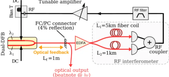
Optical feedback B ia s T RF RF filter L1=5km fiber coil L2=1km RF coupler FC/PC connector (4% reflection) RF interferometer Lf =1m Dual-DFB Tunable amplifier EDFA λ1 λ2FIG. 1. Experimental setup.
wavelengths λ1 and λ2 around 1.5 µm. Such monolithic
dual-DFBs, detailed in Ref. [8], have proven to be ef-ficient for heterodyning, as the lasers are identical by design and experience almost the same frequency drifts caused by environmental fluctuations. The frequency dif-ference can be controlled by the two pump currents from quasi-DC up to tens of GHz. We choose here to operate at a frequency difference δν = 10 GHz. Additionally, the pump current of one laser can be modulated with a RF signal, superimposed on its DC input by a bias tee (as shown on Fig.1). The modulation bandwidth of the laser has been measured to be about 14 GHz at−3 dB cutoff frequency.
The lasers are combined by an on-chip−3 dB coupler, and the output is then injected into a Lf= 1 m-long
mi-crolensed single-mode fiber, in which around 500 µW of power can be coupled. This fiber is connected to a flat FC/PC connector, leadint to a 4% optical feedback into the lasers. The rest of the signal goes through two optical paths of different lengths (L1 = 5 km and L2 = 1 km),
and each of them ends on a Nortel PP-10G photodiode. The RF signals are recombined by a directional RF cou-pler. Thus, the summation of the two delayed signals acts as a RF interferometer, with very selective phase resonances. This technique has been proven to be very efficient for reducing spurious phase noise resonances in standard OEOs [9]. It has also been used as an opto-microwave frequency discriminator in activly stabilized of dual-frequency lasers [10].
The resulting signal is then filtered by a 80 MHz BW bandpass filter (Lorch, model CF7), centered at 10 GHz. After an amplification stage, it is fed back into the RF input of one of the lasers, generating small modulation
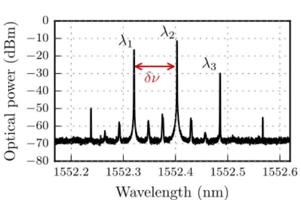
2 1552.2 1552.3 1552.4 1552.5 1552.6 Wavelength (nm) −80 −70 −60 −50 −40 −30 −20 −10 0 Optical p ow er (dBm) δν λ1 λ2 λ3
FIG. 2. Output optical spectrum, monitored by an optical spectrum analyser (OSA). The output signal is the beatnote at frequency difference δν = 10 GHz.
sidebands, i.e., lower than−20 dB around λ2. Owing to
the optical feedback, these modulation sidebands lead to mutual optical injection between the two lasers, which causes their optical phases to lock, thus stabilizing their frequency difference. A typical output optical spectrum is reported in Fig. 2. The three main peaks correspond to the emission at λ1 and λ2, and to one modulation
sideband of DFB2 respectively (the other sideband being coincident with the optical frequency λ1 of DFB). We
point out that the residual peaks at level <−55 dBm are spurs caused by the detection setup (OSA Apex 2083A). If the output signal is submitted to dispersion fading, for instance in a long fiber link, the presence of a third optical wavelength λ3 will not deteriorate significantly
the quality beatnote modulation, as the amplitude level of this wavelength is 15 db below that of λ2. Indeed, the
beating between λ2 and λ3 may interfere destructively
with the beating between λ1 and λ2, but a
straightfor-ward calculation shows that the modulation depth reduc-tion is expected to be less than−1.6 dB.
−200 −100 0 100 200 −80 −60 −40 −20 0 Beatnote PSD (dBm) (a) −0. 4 −0. 2 0.0 0.2 0.4 (b) Relative frequency f− 10 GHz (MHz)
FIG. 3. Experimental RF spectrum with two different spans. (a) RBW = 1 MHz, (b) RBW = 10 kHz
STABILITY
We measure the RF spectrum at the output of a Dis-covery 401HG photodiode. Without any stabilization, the beanote linewidth is 600 kHz [8]. When the opto-electronic loop is closed, the linewidth is dramatically reduced to less than 100 Hz. A look at the electrical spectrum on Fig. 3 shows a 40 dB rejection between the carrier and the surrounding spurs. Under our laboratory conditions, the beatnote remains stabilized for hours.
On the largest span (Fig. 3a), it can be noted that external cavity modes, linked to the delay introduced by the optical feedback, and expected to be seen at 1/τf = c/2nLf = 75 MHz are completely filtered out by
the commercially-available RF filter. This removes the possibility for mode hopping on another external cavity mode, and contributes to a greater frequency stability compared to a stabilization scheme with a longer opti-cal feedback [5]. The smaller span of Fig. 3b shows the filtering effect of the dual-loop setup, as resonant fre-quencies from the two RF delays, respectively at 40 kHz and 200 kHz contribute to residual spurs at a level lower than 40dB from carrier.
100 1k 10k 100k 1M Offset frequency (Hz) −120 −110 −100 −90 −80 −70 −60 −50 −40 −30 Phase noise (dBc/Hz)
FIG. 4. Measured phase noise of the RF beatnote
PHASE NOISE PERFORMANCES
Electrical phase noise of the RF signal was measured using a Rohde & Schwarz FSVP, and is presented on Fig. 4. It reaches less than−70 dBc/Hz at 1 kHz offset from the carrier. Above 20 kHz, sharp spurious reso-nances associated with the RF delays can be seen, but the two-coils RF interferometer scheme allows to keep the phase noise below−75 dBc/Hz. This is a strong improve-ment compared to the single-coil scheme, which features peaks up to−50 dBc/Hz. Cautious engineering, based on a precise characterization of the noise sources, could be done to tune the length of the fibers and reduce this value by a few dBc/Hz [11]. At low frequencies, better phase noise performances would be reached by implementing
3 techniques found in standard OEO, such as additional
feedback loops and temperature control on the fibers.
CONCLUSION
We have presented an efficient way to self-stabilize the frequency difference between two DFB lasers, combining optically injected semiconductor lasers and techniques commonly found in OEO designs, such as the dual RF-loop scheme.
At variance with [5], we did not use any intensity mod-ulator nor optical amplifier, thus reducing drastically the length of the optical feedback loop and preventing mode-hopping of the oscillator. We have shown that the use of current modulation does not have an important impact on the amplitude of the generated RF signal, inducing only negligible dispersion fading.
The ability to shorten the optical feedback path opens interesting perspectives towards an integrated self-stabilized heterodyne oscillator. Further miniaturization would require optical components with more integrated features. Preliminary work has already been done in this direction [12]. Finally, an all-integrated setup would ben-efit from much more compact optical delay lines, such as optical microresonators.
This work benefits from partial funding of European Defense Agency (EDA) through the HIPPOMOS project.
[1] G. H. Smith, D. Novak, and Z. Ahmed, “Overcoming chromatic-dispersion effects in fiber-wireless systems in-corporating external modulators,” IEEE Trans. Microw. Theory Tech., vol. 45, no. 8, pp. 1410–1415, 1997. [2] J. Park, W. V. Sorin, and K. Y. Lau, “Elimination
of the fibre chromatic dispersion penalty on 1550 nm millimetre-wave optical transmission,” Electron. Lett., vol. 33, no. 6, pp. 512–513, 1997.
[3] J.-P. Zhuang and S.-C. Chan, “Tunable photonic mi-crowave generation using optically injected semiconduc-tor laser dynamics with optical feedback stabilization,” Opt. Lett., vol. 38, no. 3, pp. 344–346, 2013.
[4] J. Yao, “Microwave Photonics,” J. Light. Technol., vol. 27, pp. 314–335, Feb. 2009.
[5] M. Vallet, M. Romanelli, G. Loas, F. van Dijk, and M. Alouini, “Self-stabilized optoelectronic oscillator us-ing frequency-shifted feedback and a delay line,” IEEE Photonics Technol. Lett., vol. 28, 2016.
[6] S. Wieczorek, B. Krauskopf, T. Simpson, and D. Lenstra, “The dynamical complexity of optically injected semi-conductor lasers,” Phys. Rep., vol. 416, no. 1, pp. 1–128, 2005.
[7] L. Maleki, “The optoelectronic oscillator,” Nat. Photon-ics, vol. 5, no. 12, p. 728, 2011.
[8] F. van Dijk, A. Accard, A. Enard, O. Drisse, D. Make, and F. Lelarge, “Monolithic dual wavelength DFB lasers for narrow linewidth heterodyne beat-note generation,” in Microwave Photonics, 2011 International Topical Meeting on & Microwave Photonics Conference, 2011 Asia-Pacific, MWP/APMP, pp. 73–76, IEEE, 2011. [9] X. S. Yao, L. Maleki, Y. Ji, G. Lutes, and M. Tu,
“Dual-loop opto-electronic oscillator,” in Frequency Con-trol Symposium, 1998. Proceedings of the 1998 IEEE In-ternational, pp. 545–549, IEEE, 1998.
[10] G. Pillet, L. Morvan, M. Brunel, F. Bretenaker, D. Dolfi, M. Vallet, J.-P. Huignard, and A. Le Floch, “Dual-Frequency Laser at 1.5 µm for Optical Distribution and Generation of High-Purity Microwave Signals,” J. Light. Technol., vol. 26, pp. 2764–2773, Aug. 2008.
[11] O. Lelievre, V. Crozatier, P. Berger, G. Baili, O. Llopis, D. Dolfi, P. Nouchi, F. Goldfarb, F. Bretenaker, L. Mor-van, and G. Pillet, “A Model for Designing Ultralow Noise Single- and Dual-Loop 10-GHz Optoelectronic Os-cillators,” J. Light. Technol., vol. 35, pp. 4366–4374, Oct. 2017.
[12] P. Primiani, F. van Dijk, M. Lamponi, M. Chtioui, M. Vallet, M. Romanelli, and M. Alouini, “Tunable op-toelectronic oscillator based on an integrated heterodyne source,” in Microwave Photonics (MWP), 2016 IEEE International Topical Meeting On, pp. 251–254, IEEE, 2016.